step motor
Bạn đang xem bản rút gọn của tài liệu. Xem và tải ngay bản đầy đủ của tài liệu tại đây (71.74 KB, 4 trang )
1
AVR360: Step Motor Controller
Features
• High-speed Step Motor Controller
• Interrupt Driven
• Compact Code (Only 10 Bytes Interrupt Routine)
• Very High Speed
• Low Computing Requirement
• Supports all AVR Devices
Introduction
This application note describes how to implement a compact size and high-speed
interrupt driven step motor controller. Step motors are typically used in applications
like camera zoom/film feeder, fax machines, printers, copying machines, paper feed-
ers/sorters and disk drives.
The high performance of the AVR controller enables the designer to implement high
speed step motor applications with low computing requirements of the controller.
Theory of Operation
A DC step motor translates current pulses into motor rotation. A typical motor contains
four winding coils. The coils are often labeled red, yellow/white, red/white and yellow,
but may have other colors. Applying voltage to these coils forces the motor to step one
step.
In normal operation, two winding coils are activated at the same time. The step motor
moves clockwise one step per change in winding activated. If the sequence is applied
in reverse order, the motor will run counterclockwise.
The speed of rotation is controlled by the frequency of the pulses. Every time a pulse
is applied to the step motor the motor will rotate a fixed distance. A typical step rota-
tion is 1.8 degrees. With 1.8 degree rotation in each step will a complete rotation of the
motor (360 degrees) require 200 steps.
By changing the interval of the timer interrupts, the speed of the motor can be regu-
lated, and by counting the number of steps, the rotation angle can be controlled.
8-bit
Microcontroller
Application
Note
Rev. 1181B–AVR–04/03
2
AVR360
1181B–AVR–04/03
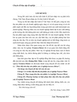
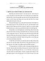
Figure 1. Step Motor Step Sequence
Table 1 shows the hexadecimal values to be output to the step motor to perform each
step.
Software Description The software uses a 16 bits timer with capture function to generate interrupt every
100 µs. When the interrupt is executed, a new step value is output to PORTB.
Values for the step motor are stored in Flash memory. At startup, the values are copied
to SRAM to achieve faster access and maximum speed performance.
In this implementation, the interrupt routine takes seven cycles + four cycles to enter
and four cycles to exit the interrupt. This totals 15 cycles. The step motor control takes
less than 2 µs. If interrupt is required every 100 µs, the step motor handling takes only
2% of the processing power in the CPU.
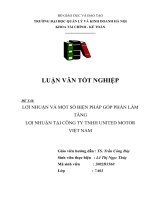
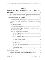
In this example the values for the step motor are stored at RAM address 0100 (hex).
The upper byte of the RAM address is constant and only the low nibble of the low byte is
used to access the address information. See Figure 2.
The lower nibble (four bits) of the variables is the actual value to control the step motor,
the upper nibble holds the address of the next value.
Table 1. Step Motor Values
Step Yellow Red/White Yellow/White Red Hex Value
0 1 0 0 1 9
1 1 1 0 0 C
2 0 1 1 0 6
3 0 0 1 1 3
YELLOW
RED/WHITE
YELLOW/WHITE
RED
STEP 0 STEP 1 STEP 2 STEP3
3
AVR360
1181B–AVR–04/03
Figure 2. Step Motor Addresses and Values
By using this method, maximum speed can be achieved, combined with a minimum of
processor resources.
Resources
ADDRESS (HEX)
0100
0101
0102
0103
ADDRESS VALUE
0001
1001
ADDRESS VALUE
0010
1100
ADDRESS VALUE
0011
0110
ADDRESS VALUE
0000
0011
VALUE (HEX)
19
2C
36
03
Table 2. CPU and Memory Usage
Function Code Size Cycles Register Usage Interrupt Description
Main 38 words – R16, XL, XH, ZL, ZH – Initialization
and example
program
OC1A 10 words 13 + return R16, XL, XH Timer 1
Output
Compare A
Output step
motor value
and calculate
next value
TOTAL 48 words – R16, XL, XH, ZL, ZH
Table 3. Peripheral Usage
Peripheral Description Interrupts Enabled
4 I/O pins Step motor output pins
Timer 1 Generate timer interrupt for step motor frequency
generation
Timer 1 Output Compare A
Printed on recycled paper.
Disclaimer: Atmel Corporation makes no warranty for the use of its products, other than those expressly contained in the Company’s standard
warranty which is detailed in Atmel’s Terms and Conditions located on the Company’s web site. The Company assumes no responsibility for any
errors which may appear in this document, reserves the right to change devices or specifications detailed herein at any time without notice, and
does not make any commitment to update the information contained herein. No licenses to patents or other intellectual property of Atmel are
granted by the Company in connection with the sale of Atmel products, expressly or by implication. Atmel’s products are not authorized for use
as critical components in life support devices or systems.
Atmel Corporation Atmel Operations
2325 Orchard Parkway
San Jose, CA 95131
Tel: 1(408) 441-0311
Fax: 1(408) 487-2600
Regional Headquarters
Europe
Atmel Sarl
Route des Arsenaux 41
Case Postale 80
CH-1705 Fribourg
Switzerland
Tel: (41) 26-426-5555
Fax: (41) 26-426-5500
Asia
Room 1219
Chinachem Golden Plaza
77 Mody Road Tsimshatsui
East Kowloon
Hong Kong
Tel: (852) 2721-9778
Fax: (852) 2722-1369
Japan
9F, Tonetsu Shinkawa Bldg.
1-24-8 Shinkawa
Chuo-ku, Tokyo 104-0033
Japan
Tel: (81) 3-3523-3551
Fax: (81) 3-3523-7581
Memory
2325 Orchard Parkway
San Jose, CA 95131
Tel: 1(408) 441-0311
Fax: 1(408) 436-4314
Microcontrollers
2325 Orchard Parkway
San Jose, CA 95131
Tel: 1(408) 441-0311
Fax: 1(408) 436-4314
La Chantrerie
BP 70602
44306 Nantes Cedex 3, France
Tel: (33) 2-40-18-18-18
Fax: (33) 2-40-18-19-60
ASIC/ASSP/Smart Cards
Zone Industrielle
13106 Rousset Cedex, France
Tel: (33) 4-42-53-60-00
Fax: (33) 4-42-53-60-01
1150 East Cheyenne Mtn. Blvd.
Colorado Springs, CO 80906
Tel: 1(719) 576-3300
Fax: 1(719) 540-1759
Scottish Enterprise Technology Park
Maxwell Building
East Kilbride G75 0QR, Scotland
Tel: (44) 1355-803-000
Fax: (44) 1355-242-743
RF/Automotive
Theresienstrasse 2
Postfach 3535
74025 Heilbronn, Germany
Tel: (49) 71-31-67-0
Fax: (49) 71-31-67-2340
1150 East Cheyenne Mtn. Blvd.
Colorado Springs, CO 80906
Tel: 1(719) 576-3300
Fax: 1(719) 540-1759
Biometrics/Imaging/Hi-Rel MPU/
High Speed Converters/RF Datacom
Avenue de Rochepleine
BP 123
38521 Saint-Egreve Cedex, France
Tel: (33) 4-76-58-30-00
Fax: (33) 4-76-58-34-80
Web Site
1181B–AVR–04/03 0M
© Atmel Corporation 2003. All rights reserved. Atmel
®
and combinations thereof, AVR
®
are the registered
trademarks of Atmel Corporation or its subsidiaries. Other terms and product names may be the trademarks of
others.