OPTICAL COHERENCE TOMOGRAPHY ppt
Bạn đang xem bản rút gọn của tài liệu. Xem và tải ngay bản đầy đủ của tài liệu tại đây (32.71 MB, 194 trang )
OPTICAL COHERENCE
TOMOGRAPHY
Edited by Masanori Kawasaki
Optical Coherence Tomography
/>Edited by Masanori Kawasaki
Contributors
Martine Mauget-Faÿsse, Benjamin Wolff, Alexandre Matet, Vivien Vasseur, José-Alain Sahel, Hironori Kitabata, Takashi
Akasaka, Michael Leitner, Alexandra Nemeth, Elisabeth Leiss-Holzinger, Karin Wiesauer, Günther Hannesschläger,
Robert James Lowe, Ronald Gentile, Nadiya Al Kharousi, Bettina Heise, Stefan E. Schausberger, David Stifter, Carl
Arndt, Shinichi Yoshimura, Masanori Kawasaki
Published by InTech
Janeza Trdine 9, 51000 Rijeka, Croatia
Copyright © 2013 InTech
All chapters are Open Access distributed under the Creative Commons Attribution 3.0 license, which allows users to
download, copy and build upon published articles even for commercial purposes, as long as the author and publisher
are properly credited, which ensures maximum dissemination and a wider impact of our publications. After this work
has been published by InTech, authors have the right to republish it, in whole or part, in any publication of which they
are the author, and to make other personal use of the work. Any republication, referencing or personal use of the
work must explicitly identify the original source.
Notice
Statements and opinions expressed in the chapters are these of the individual contributors and not necessarily those
of the editors or publisher. No responsibility is accepted for the accuracy of information contained in the published
chapters. The publisher assumes no responsibility for any damage or injury to persons or property arising out of the
use of any materials, instructions, methods or ideas contained in the book.
Publishing Process Manager Iva Simcic
Technical Editor InTech DTP team
Cover InTech Design team
First published March, 2013
Printed in Croatia
A free online edition of this book is available at www.intechopen.com
Additional hard copies can be obtained from
Optical Coherence Tomography, Edited by Masanori Kawasaki
p. cm.
ISBN 978-953-51-1032-3
free online editions of InTech
Books and Journals can be found at
www.intechopen.com
Contents
Preface VII
Section 1 Ophthalmology 1
Chapter 1 Current Applications of Optical Coherence Tomography in
Ophthalmology 3
Nadia Al Kharousi, Upender K. Wali and Sitara Azeem
Chapter 2 B-Scan and ‘En-Face’Spectral-Domain Optical Coherence
Tomography Imaging for the Diagnosis and Follow-Up of
White Dot Syndromes 33
Benjamin Wolff, Alexandre Matet, Vivien Vasseur, José-Alain Sahel
and Martine Mauget-Faÿsse
Chapter 3 Application of Optical Coherence Tomography and Macular
Holes in Ophthalmology 49
Robert J. Lowe and Ronald C. Gentile
Chapter 4 Optical Coherence Tomography in Neuro-Ophthalmology 77
Tony Garcia, Ghislain Bonnay, Ayman Tourbah and Carl Arndt
Section 2 Atherosclerosis 101
Chapter 5 Visualization of Plaque Neovascularization by OCT 103
Hironori Kitabata and Takashi Akasaka
Chapter 6 Optical Coherence Tomography (OCT): A New Imaging Tool
During Carotid Artery Stenting 117
Shinichi Yoshimura, Masanori Kawasaki, Kiyofumi Yamada, Arihiro
Hattori, Kazuhiko Nishigaki, Shinya Minatoguchi and Toru Iwama
Chapter 7 Optical Coherence Tomography for Coronary Artery Plaques –
A Comparison with Intravascular Ultrasound 127
Kawasaki Masanori
Section 3 Engineering 137
Chapter 8 Full Field Optical Coherence Microscopy: Imaging and Image
Processing for Micro-Material Research Applications 139
Bettina Heise, Stefan Schausberger and David Stifter
Chapter 9 Optical Coherence Tomography – Applications in Non-
Destructive Testing and Evaluation 163
Alexandra Nemeth, Günther Hannesschläger, Elisabeth Leiss-
Holzinger, Karin Wiesauer and Michael Leitner
ContentsVI
Preface
In 1991, optical coherence tomography (OCT) was initially introduced to image the transpar‐
ent tissue of eyes at a level of resolution significantly greater than conventional ultrasound
technique. OCT uses infrared light to produce images on a micrometer scale. The intensity
of the reflected light is displayed as a false color or grey scale image. OCT imaging is analo‐
gous to ultrasound B mode imaging, except that it performs imaging by measuring the in‐
tensity of reflected or back scattered light rather than acoustic waves. An optical beam is
scanned across the tissue and material, and the reflected light is measured as a function of
depth and transverse position.
Preliminary clinical studies in ophthalmology have demonstrated that OCT can non-inva‐
sively image the retina with high resolution and should be a powerful diagnostic tool for a
range of macular diseases. Then, OCT was applied to many fields of medicine and engineer‐
ing such as oncology and cardiology. This book is intended to serve as up-to-date knowl‐
edge of this technique, not only for medical doctors and students but also for researchers
and engineers. Contents of this book were divided four sections: ophthalmology, oncology,
atherosclerosis and engineering. It is our hope that this book will provide readers with com‐
prehensive information of OCT.
Finally, I wish to give special thanks to all the contributing authors and the extraordinary
staff of the open access publisher InTech, in particular Ms. Iva Simcic and Ms. Ivona Lovric,
for their tireless supports.
Masanori Kawasaki, MD, PhD, FACC, FJCC
Senior Lecturer of Department of Cardiology
Gifu University Graduate School of Medicine
Japan
Section 1
Ophthalmology
Chapter 1
Current Applications of Optical Coherence
Tomography in Ophthalmology
Nadia Al Kharousi, Upender K. Wali and
Sitara Azeem
Additional information is available at the end of the chapter
/>1. Introduction
Optical coherence tomography (OCT) was first reported in 1991 as a non-invasive, cross-sec‐
tional ocular imaging technology (Huang et al., 1991) and today is the most promising non-
contact, high resolution tomographic and biomicroscopic imaging device in ophthalmology.
It is a computerized instrument structured on the principle of low-coherence interferometry
(Huang et al., 1991; Hrynchak & Simpson., 2007) generating a pseudo-color representation
of the tissue structures, based on the intensity of light returning from the scanned tissue.
This noninvasive, noncontact and quick imaging technique has revolutionized modern oph‐
thalmology practice. The current applications of OCT have been improvised and expanded
dramatically in precision and specificity in clinical medicine and industrial applications. In
medicine, the technique has been compared to an in-vivo optical biopsy. As the resolution of
OCT has been improving with time, the localization and quantification of the tissues has ac‐
cordingly, become more refined, faster and predictable (Ryan SJ, 2006). What was initially
and mainly a posterior segment procedure, OCT has now wider applications in anterior seg‐
ment of the eye as well. The first anterior segment OCT (AS-OCT) was available in 1994. Its
current use in cornea and refractive surgery including phakic intraocular lens implantation,
laser-assisted in situ keratomileusis (LASIK) enhancement, lamellar keratoplasty and intrao‐
perative OCT has opened promising therapeutic and diagnostic options in both research
and clinical applications in ophthalmology. With an improved scan speed and resolution,
the new models of spectral-domain (SD)-OCT allow measurements with an even lower vari‐
ability (Leung et al., 2009). Due to reduced measurement errors, e.g. due to motion artifacts,
the precision to track and interpret tissues has increased sharply (Leung et al., 2011). OCT is
intended for use as a diagnostic device to aid in the detection and management of ocular
diseases, however, it is not intended to be used as the sole aid for the diagnosis. Ultra-high
© 2013 Al Kharousi et al.; licensee InTech. This is an open access article distributed under the terms of the
Creative Commons Attribution License ( which permits
unrestricted use, distribution, and reproduction in any medium, provided the original work is properly cited.
resolution (UHR) OCT is a new imaging system that is being used in several clinical and re‐
search purposes. It is an objective technique and has been used for evaluation of tear fluid
dynamics, contact lens fitting, imaging of corneal structures, and to describe the characteris‐
tics of epithelium, stroma and Descemet’s membrane in corneal dystrophies and degenera‐
tions (Wang et al., 2010; Shen et al., 2010; Shousha et al., 2010]
2. The machine
There are different models of OCT machine available in the market. This chapter is based on
observations made with Cirrus-high definition (HD) spectral domain (SD) OCT (Carl Zeiss
Meditech Inc., Dublin, CA; software version 4.0). The light source of OCT is a broadband
superluminescent diode laser with a central wavelength of 840 nm. This light generates
back-reflections from different intraretinal depths represented by different wavelengths. The
acquisition rate of Cirrus-HD-OCT is 27 000 A-scans /second. The axial and transverse reso‐
lutions are 15 and 5 µm, respectively. The vast increase in scan speed makes it possible to
acquire three-dimensional data sets. Current OCT models are mainly designed for analysis
of optic nerve head (optic disc cube), macula and anterior segment of the eye. The tomo‐
grams are stored on the computer and/or archive medium, and can be quantitatively ana‐
lyzed. A CCD video monitors the external eye and assists with scan alignment, while a line
scanning ophthalmoscope provides a clear image of the tissue addressed by the scan.
The main hardware components of the OCT include the scan acquisition optics, the interfer‐
ometer, the spectrometer, the system computer and video monitor. Before scanning the pa‐
tient looks into the imaging aperture and sees a green star-shaped target against a black
background (Figure 1). When scanning stars, the background changes to a bright flickering
red, and the patient may see thin bright lines of light, which is the scan beam moving across
the field of view. Normally, the patient can look inside the imaging aperture for several mi‐
nutes at a time without discomfort or tiredness. Patient should be instructed to look at the
center of the green target, and not at the moving lights of the scan beam. (Figure 1).
Before scanning
During scanning
Figure 1. Pattern of targets seen by the patient during OCT procedure.
Optical Coherence Tomography4
Anterior segment OCT uses light source with longer infrared wavelengths (1310 nm) to im‐
prove the penetration through light scattering tissues, such as sclera and limbus. Unlike poste‐
rior segment OCT, AS-OCT requires greater depth of field. AS-OCT also requires higher
energy levels than retinal OCT systems. Visualization of retroiridial structures is limited in
current AS-OCT, especially in presence of ocular surface opacities and heavy iris pigmenta‐
tion (Goldsmith et al., 2005]. Currently Cirrus HD-OCT versions 4.0 and 5.0 cannot be used for
anterior segment structures, however, one of the latest software updates of Stratus OCT (ver‐
sion 6.0) can measure corneal thickness and visualize structures of the anterior chamber angle.
UHR-OCT uses broadband light sources and has an axial resolution below 5 microns in the
tissue.
Intraoperative 3D SD-OCT is the current hot spot in ophthalmology. These systems are sep‐
arate from the operating microscope and surgery has to be halted while performing the
scans. An ideal intraoperative OCT system must be integrated into the operating microscope
with a head-up display so that real-time imaging of the operative field can be made without
disrupting the surgery (Tang et al., 2010).
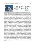
Figure 2. Optic disc cube in a normal patient. See text for details.
Current Applications of Optical Coherence Tomography in Ophthalmology
/>5
2.1. The optic disc cube (Figure 2)
This scan measures the retinal nerve fiber layer (RNFL) thickness in a 6 x 6-mm
2
area con‐
sisting of 200 x200 pixels (axial scans). The RNFL thickness is measured at each pixel and a
RNFL thickness map is generated. The optic disc (black arrow) and the cup (red arrow) are
represented in the center of the scan. A calculation circle of 3.46-mm diameter consisting of
256-A scans is automatically positioned around the optic disc. It is ideal to have signal
strength ≥ 6 for the scans. The scan gives an hour-pattern, quadrant-pattern and mean RNFL
thickness, which are color coded (white-thickest; green-normal; yellow-borderline, and red-
abnormally thin). The printout gives all credible measurements about the RNFL thickness,
rim area, disc area, cup-disc ratio and RNFL symmetry.
The scans of two eyes can be compared for symmetry. Latest models can detect saccadic eye
movements with the line-scanning ophthalmoscope overlaid with OCT en face during the
scanning. Images with motion artifact are rescanned. The SD-OCT has given a precise correla‐
tion between optic disc neuroanatomy and histomorphometric reconstruction, which in turn
helps understand the pathogenesis in glaucoma (Alexandre et al., 2012; Strouthidis et al., 2009).
2.2. The macular cube (Figure 3)
Generates a cube of data through a 6mm square grid by acquiring a series of 28 horizontal
scan lines each composed of 512 A-scans, except for the central vertical and horizontal scans,
which are composed of 1024 A-scans each. There are two versions of the macular cube,
512x128 (Figure 3) and 200x200.
Figure 3. Macular Cube 512x128 in a normal patient. N-Nasal (left hand side of image); T-temporal (right hand side of
image). 1-RNFL; 2- Normal foveal depression; 3- plexiform layer (orange-green); 4-Nuclear layer (black); 5-Retinal pig‐
ment epithelium (red band of high reflectivity); Short white arrow- External limiting membrane; long white arrow-
junction of inner and outer segments of photoreceptors (area of high reflectivity)
The 512 x 128 module has greater resolution in each line from left to right but less resolution
from top to bottom. The 200x200 module also has 6mm square grid and acquires 200 hori‐
zontal scans each composed of 200 A- scans, except for the central vertical and horizontal
scans, which are composed of 1000 A-scans each. Detailed description of the basics of OCT
and its images are available on line (Wali & Kharousi., 2012) A 3-D option offers an added
advantage in defining the lesions (Figure 4).
Optical Coherence Tomography6
Figure 4. A look-alike of a 3-dimensional figure (here on a 2 dimension surface)
2.3. Anterior segment OCT
This is a custom-built, high speed ultra high resolution device which uses a 3-module super‐
luminescent diode light source allowing an axial resolution of 2 to 3µm. This enables mor‐
phologic visualization of conjunctival and corneal architecture. (Shousa et al., 2011 & 2010).
The noninvasive nature and quick acquisition time (seconds) makes AS-OCT an ideal imag‐
ing technique in handicapped and elderly patients.
3. Current applications of OCT in clinical ophthalmology
Optical coherence tomography provides both qualitative and quantitative (thickness and
volume) analyses of the tissues examined in-situ. OCT has been exploited in evaluating both
anterior and posterior segments of the eye.
The highest impact of OCT has been in aiding the diagnosis and following the response to
treatment and in patients suffering from diabetic retinopathy (DR) (Cruz-Villegas et al.,
2004), age-related macular degeneration (ARMD) (Mavro frides et al., 2004) and venous oc‐
clusions.
Other applications include imaging morphology and lesions of posterior hyaloid like vitreo‐
macular traction (Figure 5), vitreomacular adhesion (Figure 6) (Kang et al., 2004), detection
of fluid within and under the retina which may not be visible clinically. The retinal edema
can be measured and localized to different retinal layers. Macular holes (Mavrofrides et al.,
2005) and pseudoholes can be more accurately graded, defined and differentiated. Other in‐
dications include diagnosis and defining of epiretinal membranes (ERMs) (Mori et al., 2004),
retinoschisis (Eriksson et al., 2004), retinal detachment, drug toxicities, RNFL thickness and
optic disc parameters.
OCT should not be the only criteria for diagnosis of any ocular disease. Valid perspectives of
patient’s systemic and ocular disease, clinical examination, fluorescein angiography (FA), in‐
docyanine green angiography (ICGA), biomicroscopy, and above all, the relevant history of
the disease process should always be made partner with OCT imaging.
Current Applications of Optical Coherence Tomography in Ophthalmology
/>7
Figure 5. Vitreomacular traction (yellow arrows) by posterior hyaloid membrane (red arrows) causing retinoschisis
(white arrows). S-superior (right side of image); I-Inferior (left side of image).
Figure 6. Vitreomacular adhesion: A taught thick posteior hyaloid face (yellow arrows) makes areas of adhesions
(white arrow) with the retinal surface producing marked irregularity (bumps) of the retinal tissue (red arrow). Note the
hard exudates (white box) and marked retinal thickening due to subretinal fluid (white triangle)
3.1. Anterior segment
There are several advantages of AS-OCT over conventional imaging methods like slit illumi‐
nation, slit-scanning tomography, Scheimpflug imaging and ultrasound biomicroscopy
(UBM). The imaging resolution of AS-OCT is higher than these modalities and gives high
resolution cross-sectional 3D images of the anterior segment (Dawczynski et al., 2007; Tan et
al., 2011; Goldsmith et al., 2005) Recent models of AS-OCT provide topographic analysis, an‐
terior and posterior elevation maps of the cornea and reliable pachymetric maps (Milla et al.,
2011; Nakagawa et al., 2011). It is an ideal research tool to demonstrate ciliary body contrac‐
tion and lens movement during accommodation (Baikoff et al., 2004).
3.1.1. Cornea and refractive surgery
AS-OCT can be used to determine presurgical parameters in planning different anterior seg‐
ment procedures. These parameters include anterior chamber depth, crystalline lens rise (dis‐
tance between anterior pole of crystalline lens and the line joining two iridocorneal angle lines)
and anterior chamber angle morphology with reference to the scleral spur (Dawczynski et al.,
2007; Tan et al., 2011; Goldsmith et al., 2005). Such parameters can also be used to analyze post-
surgical chamber angle dynamics and in intraocular lens (IOL) power calculations (Dinc et al.,
Optical Coherence Tomography8
2010; Tan et al., 2011) Phakic IOL is becoming a very popular refractive surgery technique for
treatment of high refractive errors. AS-OCT simulates the position of the phakic IOL before
surgery by evaluation of anterior segment structures (Mamalis N., 2010). Postoperatively AS-
OCT can visualize the contact between the collamer refractive lens and the crystalline lens
(Lindland et al., 2010). In cataract surgery AS-OCT has been instrumental in analyzing the
structure, integrity and configuration of corneal incisions after cataract surgery (Jagow Von &
Kohnen., 2009) yielding information about corneal wound architecture, Descemet’s detach‐
ment and wound leaks. Studies with AS-OCT have also revealed that corneal epithelial clo‐
sure after cataract surgery was completed in 1-8 days (Can et al., 2011; Torres et al., 2006),
postoperative Descemet’s detachment occurred in 40-82% of patients on day one (Fukuda et
al., 2011] and that stromal hydration persisted for up to 7 days.
AS-OCT has proved very useful in early recognition of localized or total graft dislocation in
Descemet stripping automated endothelial keratoplasty (DSAEK), especially in eyes with
corneal edema and limited anterior chamber visualization (Kymionis et al., 2010). The tech‐
nique can also aid in diagnosis of eccentric trephination and inverse implantation of the do‐
nor (Ide et al., 2008; Kymionis et al., 2007; Suh et al., 2008). AS-OCT has been pivotal in
documenting the cause of hyperopic shift in DSAEK eyes, which was induced by a high ra‐
tio of central graft thickness to peripheral graft thickness (Yoo et al., 2008). Epithelial in
growth in refractive surgery can be confirmed by OCT images (Stahl et al., 2007).
OCT imaging and femtosecond laser-assisted surgeries are the most rapidly advancing tech‐
nologies in modern day ophthalmology. Thickness is an important parameter in refractive
surgery and no technique other than OCT can give accurate, uniform and predictable thick‐
ness measurements before, during and after surgery. The pachymetry map of AS-OCT can
be used in femtosecond laser-assisted astigmatic keratotomy, LASIK enhancement and in‐
trastromal tunnel preparation for intracorneal ring segments (Hoffart et al., 2009; Nubile et
al., 2009). AS-OCT is very helpful in determining the accurate depth of the arcuate incisions,
and in the postoperative follow up of patient with femtosecond astigmatic keratotomy and
intracorneal ring segments. The images can explain the reasons behind unexpected postsur‐
gical surprises (Yoo & Hurmeric., 2011). Femtosecond-assisted lamellar keratoplasty (FALK)
is a highly promising refractive surgical technique that requires OCT data in accurate pre‐
surgical planning (Yoo et al., 2008). These procedures include anterior lamellar keratoplasty
and deep anterior lamellar keratoplasty. AS-OCT imaging is the first step to measure the
depth of anterior stromal scar and this determines the preparation of the donor and the re‐
cipient corneas. The morphology of the perfect match (donor and recipient) is confirmed by
AS-OCT imaging. AS-OCT helps in careful planning of structure, thickness and shape of
LASIK flap (Li et al., 2007; Rosas et al., 2011]. It is the depth of corneal incisions as obtained
from AS-OCT that determines the success of new surgical techniques like femtosecond-as‐
sisted corneal biopsies, corneal tattooing and collagen crosslinking (Kymionis et al., 2009;
Kanellopoulos et al.,2009; Nagy et al., 2009).
New platforms provide integrated OCT systems in the operating microscopes to perform
the anterior segment procedures like corneal incisions, continuous curvilinear capsulorrhex‐
is, nucleus softening, lens fragmentation, and focusing the laser in 3D manner in femtosec‐
ond-assisted cataract surgery (William et al., 2011; Wang et al., 2009).
Current Applications of Optical Coherence Tomography in Ophthalmology
/>9
Another milestone in OCT technology has been development of intraoperative 3D SD-OCT
in the supine position (Dayani et al., 2009). This technique has been used for intraoperative
evaluation of the presence of interface fluid between the donor and the recipient corneas in
DSAEK.
3.1.2. Ocular surface disorders
OCT can be used for assessment of conjunctival and corneal tissue planes with high axial
resolution. (Christopoulas et al., 2007 ; Shousha et al., 2011]. The technique acts as an adju‐
vant tool in diagnosing ocular surface squamous neoplasia and pterygia (Jeremy et al.,2012).
OCT is in potential use for diagnosis and patient follow-up during the course of medical
treatment and continued watch for recurrence of neoplasia without any need for repeated
biopsies. Also the technique may be helpful in determining the extent of the tumor to facili‐
tate its complete excision. AS-OCT guided subtenon injections of drugs like triamcinolone
has reduced chances of inadvertent perforations and unwanted targets.
3.1.3. Glaucoma (anterior segment)
Recently Fourier-domain OCT has been used to examine the position, patency and the inte‐
rior entrance site of the anterior chamber aqueous tube shunts. This high resolution OCT
shows exact position of the AC entrance relative to Schwalbe’s line and growth of fibrous
tissue between the tube and the corneal endothelium. Such findings could not be seen with
slit-lamp examination or lower resolution time-domain OCT. The tube position visualized
by slitlamp examination differed from OCT finding (Jiang et al., 2012). OCT is also very
helpful in correlating the clinical and visual field changes in glaucoma and ocular hyperten‐
sion patients (Figure 7 & 8).
Figure 7. Fundus photo showing glaucomatous cupping temporaly.
Optical Coherence Tomography10
Figure 8. OCT printout of optic disc cube showing glaucomatous changes. The red measurements indicate abnormal
thinning of RNFL, yellow areas represent borderline thickness of RNFL and green areas mean normal thickness of
RNFL.
3.1.4. Ultrahigh Resolution (UHR) OCT
Ultrahigh resolution (UHR) OCT has been more practical and advantageous over confocal
microscopy in making a clear distinction between morphologic and histopathologic features
between normal and abnormal epithelium in ocular surface squamous neoplasia and ptery‐
gia. This is so because OCT is a noncontact method, has rapid image capture, and provides a
cross-sectional view of the tissue. One of the recent clinical applications of UHR- OCT is the
identification of the opaque bubble layer as a bright white area in mid stroma in femtosec‐
ond laser-assisted LASIK flap creation (Nordan et al., 2003). This technique has been of im‐
mense help to refractive surgeons in analyzing the flap integrity, indistinct flap interface or
epithelial breakthrough in LASIK surgery (Seider et al., 2008; Ide et al., 2009; Ide et al., 2010).
OCT is not a substitute for histopathologic specimens; however, it can be a potential nonin‐
vasive diagnostic adjuvant in diagnosis and surveillance of anterior segment pathologies of
the eye.
Current Applications of Optical Coherence Tomography in Ophthalmology
/>11
3.2. Posterior segment
OCT now has a role in varied types of posterior segment pathologies (inflammatory, non-
inflammatory, degenerative, vascular, traumatic, neoplastic, and metastatic) where the tech‐
nique clearly defines the levels of various pathologic lesions in the posterior hyaloid, retina,
retinal pigment epithelium and choroid, which in turn defines the mode and success of ther‐
apy. Such lesions may be superficial (epiretinal and vitreous membranes (Figures 6, 9 and
10), cotton wool spots, retinal hemorrhages, hard exudates (Figure 11), cysts (Figure 12), reti‐
nal fibrosis, and retinal scars (Figure 13) or deep (drusen-Figure 14), retinal pigment epithe‐
lial hyperplasia and detachment (Figure 15), intraretinal and subretinal neovascular
membranes (Figure 16), scarring (figure 13) and pigmented lesions).
Figure 9. Epiretinal membrane (arrow) causing ripping of retinal tissue
Figure 10. Retinal infoldings due to epiretinal membrane: 1: color map showing marked thickening (silver white and
red areas) of ILM (internal limiting membrane)-RPE (retinal pigment epithelium) interface. 2: grey tone video image
showing irregular surface with striations due to fibrous membrane. 3: ILM map showing marked irregularity due to
contraction of the fibrous membrane. 4: A relatively intact RPE. Note the teeth-like infoldings of the retinal surface
(yellow arrows) produced by ERM.
Optical Coherence Tomography12
Figure 11. Hard exudates (white arrows). White triangle indicates the shadow cast by the exudate. The ILM-RPE color
map shows three humps due to exudates.
Figure 12. Solitary macular cyst (arrows). Note the blisters (black arrows) in the color map, corresponding to the cyst.
Figure 13. A: Extensive retinal scarring in a thin atrophic retina (orange red hyperreflective band between arrows).
13B- Scarring following involution of CNVM (arrow)
Current Applications of Optical Coherence Tomography in Ophthalmology
/>13
Figure 14. Drusen with bumps in the RPE (arrows). The drusen bumps produce characteristic humps in the color maps
of ILM-RPE interface.
Figure 15. Thickened, irregular and detached RPE (arrow)
Figure 16. Myopic CNVM: Fundus photo gives a vivid description of myopic peripapillary atropy and a greyish white
neovascular membrane in the macular area (encircled). FFA shows characteristic leakage corresponding to the area of
neovascular membrane. OCT image depicts a hyperreflective subfoveal CNVM with increased retinal thickness (thick
arrow).
3.2.1. Disorders of vitreous and posterior hyaloid
Vitreomacular traction (VMT) and vitreomacular adhesion (VMA) may be difficult to detect
clinically. OCT is extremely helpful in such cases by showing hyperreflectivity. The traction
by the membrane to the retina induces deformations of the retinal surface (Figure 17).
Optical Coherence Tomography14
Figure 17. Vitreomacular traction. Note the multiple areas of traction caused by taught posterior hyaloid on retinal
tissue (arrows).
3.2.2. Retinal edema
The most common primary cause of retinal thickening is edema. One of the major achieve‐
ments of OCT has been quantitative assessment of retinal edema in terms of measuring its
thickness and volume, evaluate the progression of the pathologic process, and monitor sur‐
gical or non-surgical intervention (Kang et al., 2004). Retinal edema may manifest in differ‐
ent categories:
Focal or diffuse edema: Common causes include diabetic retinopathy, central retinal venous
occlusion, branch retinal venous occlusion, arterial occlusion, hypertensive retinopathy, pre-
eclampsia, eclampsia, uveitis, retinitis pigmentosa and retraction of internal limiting mem‐
brane. OCT helps in diagnosis of edema in preclinical stage when there may be no or few
visible changes.
Cystoid macular edema (CME): (Figure 18) Common causes of CME include diabetic retinop‐
athy, age-related macular degeneration (ARMD), venous occlusions, pars planitis, Uveitis,
pseudophakos, Irvine-Gass syndrome, Birdshot retinopathy and retinitis pigmentosa. OCT
usually shows diffuse cystic spaces in the outer nuclear layer of central macula, and increased
retinal thickness which is maximally concentric on the fovea (Mavrofrides et al., 2004).
Figure 18. Cystoid macular edema in a patient with CRVO. Color fundus image shows disc hemorrhage, venous tor‐
tuosity, cotton wool exudates and retinal hemorrhages. FFA shows characteristic venous staining, leakge and blocked
fluorescence due to underlying hemorrhage. OCT image depicts marked increase in retinal thickness due to edema.
Note the intraretinal cysts and subretinal fluid (arrow).
Serous retinal detachment: The cysts of retinal edema over a period of time loose their walls
and merge together forming single or multiple pools of fluid within retinal layers or between
retinal pigment epithelium (RPE) and the sensory retina (Villate et al., 2004.) (Figure 19)
Current Applications of Optical Coherence Tomography in Ophthalmology
/>15
Figure 19. Serous retinal detachment (dark zone between white arrows) in a patient with severe nonproliferative dia‐
betic retinopathy. Red arrows indicate subfoveal exudates.
3.2.3. Retinal pigment epithelial detachment (Figure 20)
Its pathophysiology involves passage of serous fluid from the choriocapillaries to the sub-
RPE space or collection of blood under RPE causing its separation and elevation from the
Bruch’s membrane. OCT scans show a classical dome-shaped detachment of the RPE with
intact contour in early stages (Figure 14).
Figure 20. RPE detachment with hyperplasia (asterisk).
3.2.4. Epiretinal membranes (ERM)
Epiretinal membranes are fibroglial proliferations on the vitreo-retinal interface (Figure 10).
They may be sequel of chronic intraocular inflammations, venous occlusions, trauma, post‐
surgical or may be idiopathic. OCT helps in confirming such membranes (Suzuki et al., 2003;
Massin et al., 2000).
3.2.5. Secondary retinal lesions
OCT is important to document the presence, degree and extent of subretinal fluid (Villate et
al., 2004), assessment of the level of retinal infiltrates and detect macular edema in patients
with chronic uveitis where hazy media may prevent clinical examination to find the cause of
reduced vision (Antcliff et al., 2002; Markomichelakis et al., 2004).
Optical Coherence Tomography16
3.2.6. Retinoschisis
It is the separation or splitting of the neurosensory retina into an inner (vitreous) and outer
(choroidal) layer with severing of neurons and complete loss of visual function in the affect‐
ed area (Figure 21). Typically the split is in the outer plexiform layer. In reticular retinoschi‐
sis, which is less common, splitting occurs at the level of nerve fiber layer. Retinoschisis may
be degenerative, myopic, juvenile or idiopathic. Presence of vitreoretinal traction is an im‐
portant cause. OCT reveals wide space with vertical palisades and splitting of the retina into
a thinner outer layer and thicker inner layer (Eriksson et al., 2004).
Figure 21. Retinoschisis: Note the splitting of retina into inner (small arrow) and outer layers (large arrow)
3.2.7. Macular holes
Lamellar hole: OCT depicts a homogenous increase in foveal and perifoveal retinal thick‐
ness, and presence of residual retinal tissue at the base of the hole (Figure 22).
Figure 22. OCT image of a lamellar thickness macular hole with residual retinal tissue remaining between the base of
the hole (arrow) and the RPE.
Current Applications of Optical Coherence Tomography in Ophthalmology
/>17