Slide thiết kế vi mạch chapter2 introduction to verilog
Bạn đang xem bản rút gọn của tài liệu. Xem và tải ngay bản đầy đủ của tài liệu tại đây (2.89 MB, 44 trang )
Digital Design with the Verilog HDL
Chapter 1: Introduction to Verilog
Dr. Phạm Quốc Cường
Adapted from Prof. Mike Schulte’s slides ()
Computer Engineering – CSE – HCMUT
CuuDuongThanCong.com
/>
1
Overview of HDLs
• Hardware description languages (HDLs)
– Are computer-based hardware description languages
– Allow modeling and simulating the functional behavior and
timing of digital hardware
– Synthesis tools take an HDL description and generate a
technology-specific netlist
• Two main HDLs used by industry
– Verilog HDL (C-based, industry-driven)
– VHSIC HDL or VHDL (Ada-based,
defense/industry/university-driven).
2
CuuDuongThanCong.com
/>
Synthesis of HDLs
• Takes a description of what a circuit DOES
• Creates the hardware to DO it
• HDLs may LOOK like software, but they’re not!
– NOT a program
– Doesn’t “run” on anything
• Though we do simulate them on computers
– Don’t confuse them!
• Also use HDLs to test the hardware you create
– This is more like software
3
CuuDuongThanCong.com
/>
Describing Hardware!
• All hardware created during
synthesis
– Even if a is true, still
computing d&e
• Learn to understand how
descriptions translated to
hardware
if (a) f = c & d;
else if (b) f = d;
else f = d & e;
c
f
d
e
b
CuuDuongThanCong.com
/>
a
4
Why Use an HDL?
• More and more transistors can fit on a chip
– Allows larger designs!
– Work at transistor/gate level for large designs: hard
– Many designs need to go to production quickly
• Abstract large hardware designs!
– Describe what you need the hardware to do
– Tools then design the hardware for you
5
CuuDuongThanCong.com
/>
Why Use an HDL?
• Simplified & faster design process
• Explore larger solution space
– Smaller, faster, lower power
– Throughput vs. latency
– Examine more design tradeoffs
• Lessen the time spent debugging the design
– Design errors still possible, but in fewer places
– Generally easier to find and fix
• Can reuse design to target different technologies
– Don’t manually change all transistors for rule change
6
CuuDuongThanCong.com
/>
Other Important HDL Features
•
•
•
•
•
Are highly portable (text)
Are self-documenting (when commented well)
Describe multiple levels of abstraction
Represent parallelism
Provides many descriptive styles
– Structural
– Register Transfer Level (RTL)
– Behavioral
• Serve as input for synthesis tools
7
CuuDuongThanCong.com
/>
Verilog
• In this class, we will use the Verilog HDL
– Used in academia and industry
• VHDL is another common HDL
– Also used by both academia and industry
• Many principles we will discuss apply to any HDL
• Once you can “think hardware”, you should be able
to use any HDL fairly quickly
8
CuuDuongThanCong.com
/>
Verilog Module
A[1:0]
• In Verilog, a circuit is a module.
2
module decoder_2_to_4 (A, D) ;
Decoder
2-to-4
input [1:0] A ;
output [3:0] D ;
assign D =
4
(A == 2'b00) ? 4'b0001 :
(A == 2'b01) ? 4'b0010 :
(A == 2'b10) ? 4'b0100 :
(A == 2'b11) ? 4'b1000 ;
D[3:0]
endmodule
9
CuuDuongThanCong.com
/>
Verilog Module
module name
A[1:0]
ports names of
module
2
module decoder_2_to_4 (A, D) ;
port
types
input [1:0] A ;
output [3:0] D ;
assign D =
Decoder
2-to-4
port
sizes
4
(A == 2'b00) ? 4'b0001 :
(A == 2'b01) ? 4'b0010 :
(A == 2'b10) ? 4'b0100 :
(A == 2'b11) ? 4'b1000 ;
endmodule
D[3:0]
module
contents
keywords underlined
CuuDuongThanCong.com
10
/>
Declaring A Module
• Can’t use keywords as module/port/signal names
– Choose a descriptive module name
• Indicate the ports (connectivity)
• Declare the signals connected to the ports
– Choose descriptive signal names
• Declare any internal signals
• Write the internals of the module (functionality)
11
CuuDuongThanCong.com
/>
Declaring Ports
• A signal is attached to every port
• Declare type of port
– input
– output
– inout (bidirectional)
• Scalar (single bit) - don’t specify a size
– input
cin;
• Vector (multiple bits) - specify size using range
–
–
–
–
Range is MSB to LSB (left to right)
Don’t have to include zero if you don’t want to… (D[2:1])
output [7:0 ] OUT;
input
[1:0] IN;
12
CuuDuongThanCong.com
/>
Module Styles
• Modules can be specified different ways
– Structural – connect primitives and modules
– RTL – use continuous assignments
– Behavioral – use initial and always blocks
• A single module can use more than one method!
• What are the differences?
13
CuuDuongThanCong.com
/>
Structural
• A schematic in text form
• Build up a circuit from gates/flip-flops
– Gates are primitives (part of the language)
– Flip-flops themselves described behaviorally
• Structural design
–
–
–
–
Create module interface
Instantiate the gates in the circuit
Declare the internal wires needed to connect gates
Put the names of the wires in the correct port locations of
the gates
• For primitives, outputs always come first
14
CuuDuongThanCong.com
/>
Structural Example
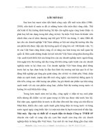
module majority (major, V1, V2, V3) ;
output major ;
input V1, V2, V3 ;
wire N1, N2, N3;
and A0 (N1, V1, V2),
A1 (N2, V2, V3),
A2 (N3, V3, V1);
or Or0 (major, N1, N2, N3);
endmodule
V1
V2
A0
V2
V3
A1
V3
V1
A2
N1
N2
Or0
major
N3
majority
15
CuuDuongThanCong.com
/>
RTL Example
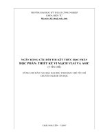
module majority (major, V1, V2, V3) ;
output major ;
input V1, V2, V3 ;
assign major = V1 & V2
| V2 & V3
| V1 & V3;
endmodule
V1
V2
V3
majority
major
16
CuuDuongThanCong.com
/>
Behavioral Example
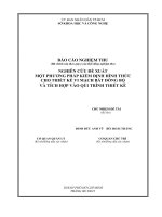
module majority (major, V1, V2, V3) ;
output reg major ;
input V1, V2, V3 ;
always @(V1, V2, V3) begin
if (V1 && V2 || V2 && V3
|| V1 && V3) major = 1;
else major = 0;
end
V1
V2
V3
majority
major
endmodule
17
CuuDuongThanCong.com
/>
Adder Example
18
CuuDuongThanCong.com
/>
Full Adder: Structural
module half_add (X, Y, S, C);
module full_add (A, B, CI, S, CO) ;
input X, Y ;
output S, C ;
input A, B, CI ;
output S, CO ;
xor SUM (S, X, Y);
and CARRY (C, X, Y);
wire S1, C1, C2;
endmodule
// build full adder from 2 half-adders
half_add PARTSUM (A, B, S1, C1);
hafl_add
SUM (S1, CI, S, C2);
// … and an OR gate for the carry
or CARRY (CO, C2, C1);
endmodule
CuuDuongThanCong.com
19
/>
Full Adder: RTL/Dataflow
module fa_rtl (A, B, CI, S, CO) ;
input A, B, CI ;
output S, CO ;
// use continuous assignments
assign S = A ^ B ^ CI;
assign C0 = (A & B) | (A & CI) | (B & CI);
endmodule
20
CuuDuongThanCong.com
/>
Full Adder: Behavioral
• Circuit “reacts” to given events (for simulation)
– Actually list of signal changes that affect output
module fa_bhv (A, B, CI, S, CO) ;
input A, B, CI;
output S, CO;
reg S, CO;
// explained in later lecture – “holds” values
// use procedural assignments
always@(A or B or CI)
begin
S = A ^ B ^ CI;
CO = (A & B) | (A & CI) | (B & CI);
end
endmodule
CuuDuongThanCong.com
21
/>
Full Adder: Behavioral
• IN SIMULATION
– When A, B, or C change, S and CO are recalculated
• IN REALITY
– Combinational logic – no “waiting” for the trigger
– Constantly computing - think transistors and gates!
– Same hardware created for this and RTL example
always@(A or B or CI)
begin
S = A ^ B ^ CI;
CO = (A & B) | (A & CI) | (B & CI);
end
CuuDuongThanCong.com
A
B
CI
S
majority
fa_bhv
/>
CO
22
Structural Basics: Primitives
• Build design up from the gate/flip-flop/latch level
– Flip-flops actually constructed using Behavioral
• Verilog provides a set of gate primitives
–
–
–
–
and, nand, or, nor, xor, xnor, not, buf, bufif1, etc.
Combinational building blocks for structural design
Known “behavior”
Cannot access “inside” description
• Can also model at the transistor level
– Most people don’t, we won’t
23
CuuDuongThanCong.com
/>
Primitives
• No declarations - can only be instantiated
• Output port appears before input ports
• Optionally specify: instance name and/or delay
(discuss delay later)
and N25 (Z, A, B, C); // name specified
and #10 (Z, A, B, X),
(X, C, D, E); // delay specified, 2 gates
and #10 N30 (Z, A, B); // name and delay specified
24
CuuDuongThanCong.com
/>
Verilog Primitives
• 26 pre-defined primitives
• Output is the first port
n-input
n-output
3-states
and
buf
nand
not
or
bufif0
nor
bufif1
xor
notif0
xnor
notif1
output ending mark
nand (y, a, b, c);
input
keyword name
nand N1(y, a, b, c);
instance name (optional)
25
CuuDuongThanCong.com
/>