Slide thiết kế vi mạch chapter3 hierarchy simulation
Bạn đang xem bản rút gọn của tài liệu. Xem và tải ngay bản đầy đủ của tài liệu tại đây (1.12 MB, 34 trang )
Digital Design with the Verilog HDL
Chapter 3: Hierarchy & Simulation
Dr. Phạm Quốc Cường
Adapted from Prof. Mike Schulte’s slides ()
Computer Engineering – CSE – HCMUT
CuuDuongThanCong.com
/>
1
Module Port List
• Multiple ways to declare the ports of a module
module Add_half(c_out, sum, a, b);
output sum, c_out;
input a, b;
…
endmodule
module Add_half(output c_out, sum,
input a, b);
…
endmodule
2
CuuDuongThanCong.com
/>
Module Port List
• Multiple ways to declare the ports of a module
module xor_8bit(out, a, b);
output [7:0] out;
input [7:0] a, b;
…
endmodule
module xor_8bit(output [7:0] out, input [7:0] a, b);
…
endmodule
3
CuuDuongThanCong.com
/>
Structural Design Tip
•
•
•
•
If a design is complex, draw a block diagram!
Label the signals connecting the blocks
Label ports on blocks if not primitives/obvious
Easier to double-check your code!
• Don’t bother with 300-gate design…
• But if that big, probably should use hierarchy!
4
CuuDuongThanCong.com
/>
Example: Hierarchy Multiplexer
mux_8_to_1(output out, input in0, in1, in2, in3, in4,
in5, in6, in7, input [2:0] select);
5
CuuDuongThanCong.com
/>
Interface: Hierarchical Multiplexer
module mux_2_to_1(output out,
input in0, in1
input select);
wire n0, n1, n2;
endmodule
6
CuuDuongThanCong.com
/>
Interface: Hierarchical Multiplexer
module mux_8_to_1(output out,
input in0, in1, in2, in3, in4, in5, in6, in7,
input [2:0] select);
wire n0, n1, n2, n3, n4, n5;
endmodule
7
CuuDuongThanCong.com
/>
Timing Controls For Simulation
• Can put “delays” in a Verilog design
– Gates, wires, even behavioral statements!
• SIMULATION
– Used to approximate “real” operation while simulating
– Used to control testbench
• SYNTHESIS
– Synthesis tool IGNORES these timing controls
• Cannot tell a gate to wait 1.5 nanoseconds!
• Delay is a result of physical properties!
– Only timing (easily) controlled is on clock-cycle basis
• Can tell synthesizer to attempt to meet cycle-time restriction
8
CuuDuongThanCong.com
/>
Zero Delay vs. Unit Delay
• When no timing controls specified: zero delay
– Unrealistic – even electrons take time to move
– OUT is updated same time A and/or B change:
and(OUT, A, B)
• Unit delay often used
–
–
–
–
Not accurate either, but closer…
“Depth” of circuit does affect speed!
Easier to see how changes propagate through circuit
OUT is updated 1 “unit” after A and/or B change:
and #1 A0(OUT, A, B);
9
CuuDuongThanCong.com
/>
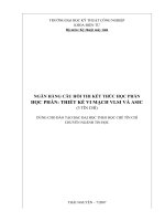
Zero/Unit Delay Example
A
B
C
Y
Z
Unit Delay
Zero Delay
Zero Delay:
Y and Z change at
same “time” as A, B,
and C!
Unit Delay:
Y changes 1 unit after
B, C
Unit Delay:
Z changes 1 unit after
A, Y
T
0
1
2
3
4
5
6
7
8
9
10
11
12
13
14
15
A
0
0
0
0
1
1
1
1
0
0
0
0
1
1
1
1
B
0
0
1
1
0
0
1
1
0
0
1
1
0
0
1
1
C
0
1
0
1
0
1
0
1
0
1
0
1
0
1
0
1
Y
0
0
0
1
0
0
0
1
0
0
0
1
0
0
0
0
Z
0
0
0
1
1
1
1
1
0
0
0
1
1
1
1
1
T
0
1
2
3
4
5
6
7
8
9
10
11
12
13
14
15
16
A
0
0
0
0
0
0
1
1
1
1
1
1
0
0
0
0
0
B
1
1
1
1
1
1
0
0
1
1
0
0
1
1
1
1
1
C
0
0
0
1
1
1
0
0
1
1
0
0
0
0
1
1
1
Y
x
0
0
0
1
1
1
0
0
1
1
0
0
0
0
1
1
Z
x
x
0
0
0
1
1
1
1
1
1
1
1
0
0
0
1
10
CuuDuongThanCong.com
/>
Types Of Delays
• Inertial Delay (Gates)
– Suppresses pulses shorter than delay amount
– In reality, gates need to have inputs held a certain time before
output is accurate
– This models that behavior
• Transport Delay (Nets)
– “Time of flight” from source to sink
– Short pulses transmitted
• Not critical for most of class
– May need to know when debugging
– Good to know for building very accurate simulation
11
CuuDuongThanCong.com
/>
Delay Examples
• wire #5 net_1;
// 5 unit transport delay
• and #4 (z_out, x_in, y_in); // 4 unit inertial delay
• assign #3 z_out = a & b; // 3 unit inertial delay
• wire #2 z_out;
// 2 unit transport delay
• and #3 (z_out, x_in, y_in); // 3 for gate, 2 for wire
• wire #3 c;
• assign #5 c = a & b;
// 3 unit transport delay
// 5 for assign, 3 for wire
12
CuuDuongThanCong.com
/>
Delays In Testbenches
• Most common use in class
• Single testbench tests many possibilities
– Need to examine each case separately
– Spread them out over “time”
• Use to generate a clock signal
– Example later in lecture
13
CuuDuongThanCong.com
/>
Simulation
• Update only if changed
0
0
1
1
0
1
1
1
1
1
1
0
0
0
1
0
0
0
1
1
1
1
• Some circuits are very large
– Updating every signal => very slow simulation
– Event-driven simulation is much faster!
17
CuuDuongThanCong.com
/>
Simulation of Verilog
• Need to verify your design
– “Unit Under Test” (UUT)
• Use a “testbench”!
– Special Verilog module with no ports
– Generates or routes inputs to the UUT
– Outputs information about the results
Outputs
OR
UUT
(Response)
Testbench
Stimulus
Inputs
Inputs
Outputs
UUT
(Response)
Testbench
CuuDuongThanCong.com
/>
18
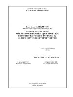
Simulation Example
module adder4b (sum, c_out, a, b, c_in);
input
[3:0] a, b;
input
c_in;
output
[3:0] sum;
output
c_out;
assign {c_out, sum} = a + b + c_in;
endmodule
4
a[3:0]
b[3:0]
4
4
adder4b
sum[3:0]
c_out
c_in
19
CuuDuongThanCong.com
/>
Simulation Example
t_adder4b
4
a[3:0]
b[3:0]
4
4
adder4b
(UUT)
sum[3:0]
c_out
c_in
• Testbenches frequently named
t_<UUT name>
20
CuuDuongThanCong.com
/>
Example
not an apostrophe!
`timescale 1ns /1ns
// time_unit/time_precision
module t_adder4b;
reg[8:0] stim;
// inputs to UUT are regs
wire[3:0] S;
// outputs of UUT are wires
wire C4;
all inputs grouped into
UUT
single vector (not
// instantiate UUT
adder4b a1(S, C4, stim[8:5], stim[4:1], stim[0]); required)
// stimulus generation
initial begin
stim = 9'b000000000;
#10 stim = 9'b111100001;
Behav.
#10 stim = 9'b000011111;
Verilog:
#10 stim = 9'b111100010;
“do this
#10 stim = 9'b000111110;
#10 $stop;
once”
end
timing control for
endmodule
simulation
CuuDuongThanCong.com
//
//
//
//
//
//
at
at
at
at
at
at
0 ns
10 ns
see “response” to
20 ns
each of these input
30 ns
vectors
40 ns
50 ns – stops simulation
22
/>
Testbench Requirements
• Instantiate the unit being tested (UUT)
• Provide input to that unit
– Usually a number of different input combinations!
• Watch the “results” (outputs of UUT)
– Can watch ModelSim Wave window…
– Can print out information to the screen or to a file
23
CuuDuongThanCong.com
/>
Output Test Info
• Several different system calls to output info
– $monitor
• Output the given values whenever one changes
• Can use when simulating Structural, RTL, and/or Behavioral
– $display, $strobe
• Output specific information as if printf or cout in a program
• Used in Behavioral Verilog
• Can use formatting strings with these commands
• Only means anything in simulation
• Ignored by synthesizer
24
CuuDuongThanCong.com
/>
Output Format Strings
• Formatting string
–
–
–
–
–
%h, %H
%d, %D
%o, %O
%b, %B
%t
hex
decimal
octal
binary
time
• $monitor(“%t: %b %h %h %h %b\n”,
$time, c_out, sum, a, b, c_in);
• Can get more details from Verilog standard
25
CuuDuongThanCong.com
/>
Output Example
`timescale 1ns /1ns
module t_adder4b;
reg[8:0] stim;
wire[3:0] S;
wire C4;
// time_unit/time_precision
// inputs to UUT are regs
// outputs of UUT are wires
All values will run together,
easier to read with formatting
string
// instantiate UUT
adder4b(S, C4, stim[8:5], stim[4:1], stim[0]);
// monitor statement
initial $monitor(“%t: %b %h %h %h %b\n”, $time, C4, S, stim[8:5],
stim[4:1], stim[0]);
// stimulus generation
initial begin
stim = 9'b000000000;
// at 0 ns
#10 stim = 9'b111100001;
// at 10 ns
#10 stim = 9'b000011111;
// at 20 ns
#10 stim = 9'b111100010;
// at 30 ns
#10 stim = 9'b000111110;
// at 40 ns
#10 $stop;
// at 50 ns – stops simulation
end
CuuDuongThanCong.com
/>endmodule
26
Exhaustive Testing
• For combinational designs w/ up to 8 or 9 inputs
– Test ALL combinations of inputs to verify output
– Could enumerate all test vectors, but don’t…
– Generate them using a “for” loop!
reg [4:0] x;
initial begin
for (x = 0; x < 16; x = x + 1)
#5
// need a delay here!
end
• Need to use “reg” type for loop variable? Why?
27
CuuDuongThanCong.com
/>
Why Loop Vector Has Extra Bit
• Want to test all vectors 0000 to 1111
reg [3:0] x;
initial begin
for (x = 0; x < 16; x = x + 1)
#5
// need a delay here!
end
• If x is 4 bits, it only gets up to 1111 => 15
– 1100 => 1101 => 1110 => 1111 => 0000 => 0001
• x is never >= 16… so loop goes forever!
28
CuuDuongThanCong.com
/>
Example: UUT
module Comp_4_str(A_gt_B, A_lt_B, A_eq_B, A, B);
output A_gt_B, A_lt_B, A_eq_B;
input [3:0] A, B;
// Code to compare A to B
// and set A_gt_B, A_lt_B, A_eq_B accordingly
endmodule
29
CuuDuongThanCong.com
/>