BS EN 00196 1 2005 pdf
Bạn đang xem bản rút gọn của tài liệu. Xem và tải ngay bản đầy đủ của tài liệu tại đây (494.39 KB, 36 trang )
BRITISH STANDARD
Methods of testing
cement —
Part 1: Determination of strength
The European Standard EN 196-1:2005 has the status of a
British Standard
ICS 91.100.10
12 &23<,1* :,7+287 %6, 3(50,66,21 (;&(37 $6 3(50,77(' %< &23<5,*+7 /$:
BS EN
196-1:2005
BS EN 196-1:2005
National foreword
This British Standard is the official English language version of
EN 196-1:2005. It supersedes BS EN 196-1:1995 which is withdrawn.
The UK participation in its preparation was entrusted by Technical Committee
B/516, Cement and lime, to Subcommittee B/516/12, Sampling and testing,
which has the responsibility to:
—
aid enquirers to understand the text;
—
present to the responsible international/European committee any
enquiries on the interpretation, or proposals for change, and keep the
UK interests informed;
—
monitor related international and European developments and
promulgate them in the UK.
A list of organizations represented on this subcommittee can be obtained on
request to its secretary.
Cross-references
The British Standards which implement international or European
publications referred to in this document may be found in the BSI Catalogue
under the section entitled “International Standards Correspondence Index”,
or by using the “Search” facility of the BSI Electronic Catalogue or of
British Standards Online.
This publication does not purport to include all the necessary provisions of a
contract. Users are responsible for its correct application.
Compliance with a British Standard does not of itself confer immunity
from legal obligations.
This British Standard was
published under the authority
of the Standards Policy and
Strategy Committee on
22 March 2005
Summary of pages
This document comprises a front cover, an inside front cover, the EN title page,
pages 2 to 33 and a back cover.
The BSI copyright notice displayed in this document indicates when the
document was last issued.
Amendments issued since publication
Amd. No.
© BSI 22 March 2005
ISBN 0 580 45670 6
Date
Comments
EN 196-1
EUROPEAN STANDARD
NORME EUROPÉENNE
EUROPÄISCHE NORM
February 2005
ICS 91.100.10
Supersedes EN 196-1:1994
English version
Methods of testing cement - Part 1: Determination of strength
Méthodes d'essais des ciments - Partie 1: Détermination
des résistances mécaniques
Prüfverfahren für Zement - Teil 1: Bestimmung der
Festigkeit
This European Standard was approved by CEN on 29 December 2004.
CEN members are bound to comply with the CEN/CENELEC Internal Regulations which stipulate the conditions for giving this European
Standard the status of a national standard without any alteration. Up-to-date lists and bibliographical references concerning such national
standards may be obtained on application to the Central Secretariat or to any CEN member.
This European Standard exists in three official versions (English, French, German). A version in any other language made by translation
under the responsibility of a CEN member into its own language and notified to the Central Secretariat has the same status as the official
versions.
CEN members are the national standards bodies of Austria, Belgium, Cyprus, Czech Republic, Denmark, Estonia, Finland, France,
Germany, Greece, Hungary, Iceland, Ireland, Italy, Latvia, Lithuania, Luxembourg, Malta, Netherlands, Norway, Poland, Portugal, Slovakia,
Slovenia, Spain, Sweden, Switzerland and United Kingdom.
EUROPEAN COMMITTEE FOR STANDARDIZATION
COMITÉ EUROPÉEN DE NORMALISATION
EUROPÄISCHES KOMITEE FÜR NORMUNG
Management Centre: rue de Stassart, 36
© 2005 CEN
All rights of exploitation in any form and by any means reserved
worldwide for CEN national Members.
B-1050 Brussels
Ref. No. EN 196-1:2005: E
EN 196-1:2005 (E)
Contents
Page
Foreword ............................................................................................................................................................. 3
1
Scope...................................................................................................................................................... 5
2
Normative references ........................................................................................................................... 5
3
Principle ................................................................................................................................................. 5
4
4.1
4.2
4.3
4.4
4.5
4.6
4.7
4.8
4.9
4.10
4.11
Laboratory and equipment................................................................................................................... 6
Laboratory ............................................................................................................................................. 6
General requirements for the equipment ........................................................................................... 6
Test sieves............................................................................................................................................. 6
Mixer ....................................................................................................................................................... 7
Moulds.................................................................................................................................................... 8
Jolting apparatus ................................................................................................................................ 12
Flexural strength testing apparatus.................................................................................................. 13
Compressive strength testing machine............................................................................................ 14
Jig for compressive strength testing machine ................................................................................ 15
Balance ................................................................................................................................................ 16
Timer..................................................................................................................................................... 16
5
5.1
5.2
5.3
Mortar constituents............................................................................................................................. 17
Sand...................................................................................................................................................... 17
Cement ................................................................................................................................................. 18
Water .................................................................................................................................................... 18
6
6.1
6.2
Preparation of mortar ......................................................................................................................... 18
Composition of mortar ....................................................................................................................... 18
Mixing of mortar .................................................................................................................................. 18
7
7.1
7.2
Preparation of test specimens........................................................................................................... 19
Size of specimens ............................................................................................................................... 19
Moulding of test specimens............................................................................................................... 19
8
8.1
8.2
8.3
8.4
Conditioning of test specimens ........................................................................................................ 19
Handling and storage before demoulding........................................................................................ 19
Demoulding of specimens ................................................................................................................. 19
Curing of specimens in water............................................................................................................ 20
Age of specimens for strength tests................................................................................................. 20
9
9.1
9.2
Testing procedures............................................................................................................................. 20
Flexural strength ................................................................................................................................. 20
Compressive strength ........................................................................................................................ 21
10
10.1
10.2
Results ................................................................................................................................................. 21
Flexural strength ................................................................................................................................. 21
Compressive strength ........................................................................................................................ 22
11
11.1
11.2
11.3
Validation testing of CEN Standard sand and of alternative compaction equipment ................. 23
General ................................................................................................................................................. 23
Validation testing of CEN Standard sand ......................................................................................... 23
Validation testing of alternative compaction equipment ................................................................ 27
Annex A (normative) Alternative vibration compaction equipment and procedures
validated as equivalent to the reference jolting compaction equipment and
procedure............................................................................................................................................. 29
2
EN 196-1:2005 (E)
Foreword
This document (EN 196-1:2005) has been prepared by Technical Committee CEN/TC 51 ‘Cement
and building limes’, the secretariat of which is held by IBN/BIN.
This European Standard shall be given the status of a national standard, either by publication of an
identical text or by endorsement, at the latest by August 2005, and conflicting national standards shall
be withdrawn at the latest by August 2005.
This document supersedes EN 196-1:1994.
This European Standard on the methods of testing cement comprises the following Parts:
EN 196-1, Methods of testing cement — Part 1: Determination of strength
EN 196-2, Methods of testing cement — Part 2: Chemical analysis of cement
EN 196-3, Methods of testing cement — Part 3: Determination of setting time and soundness
EN 196-5, Methods of testing cement — Part 5: Pozzolanicity test for pozzolanic cements
EN 196-6, Methods of testing cement — Part 6: Determination of fineness
EN 196-7, Methods of testing cement — Part 7: Methods of taking and preparing samples of cement
EN 196-8, Methods of testing cement — Part 8: Heat of hydration — Solution method
EN 196-9, Methods of testing cement — Part 9: Heat of hydration — Semi-adiabatic method
NOTE
A previous Part, EN 196-21: Methods of testing cement — Part 21: Determination of the chloride,
carbon dioxide and alkali content of cement, has been revised and incorporated into EN 196-2
Another document, ENV 196-4 Methods of testing cement — Part 4: Quantitative determination of
constituents, has been drafted and will be published as a CEN Technical Report.
This edition introduces the following technical changes based on comments received by the
secretariat.
a)
The testing procedure has been revised with respect to hardness and surface texture of moulds
(4.5) and compression strength testing machine platens (4.8) as supplied; suitability of mould oil
(4.5); frequency of operation of jolting apparatus (4.6); the inclusion and accuracy of a balance
(4.10); deionised water is now permitted (5.3); procedures for mixing mortar (6.2) and the
moulding (7) and conditioning (8) of test specimens have been revised to reflect current best
practice.
b)
Test results (10) are now reported in megapascals replacing newtons per square millimetre. (One
megapascal is equivalent to one newton per square millimetre).
c)
The requirement for a flexural strength testing machine (4.7) is now optional.
d)
Estimates of the precision for compressive strength testing (10.2.3) have been revised to include
both short and long term repeatability together with reproducibility data for laboratories of ‘normal’
performance and an indication of precision data for ‘expert’ laboratories.
3
EN 196-1:2005 (E)
e)
The procedure for validation testing of CEN Standard sand (11.2) includes initial certification
testing, validation criteria, verification testing and annual confirmation testing.
f)
The procedure for validation testing of alternative compaction equipment (11.3) has been revised
and a normative annex (annex A) has been introduced detailing two alternative vibration
compaction equipments which have been validated.
According to the CEN/CENELEC Internal Regulations, the national standards organizations of the
following countries are bound to implement this European Standard: Austria, Belgium, Cyprus, Czech
Republic, Denmark, Estonia, Finland, France, Germany, Greece, Hungary, Iceland, Ireland, Italy,
Latvia, Lithuania, Luxembourg, Malta, Netherlands, Norway, Poland, Portugal, Slovakia, Slovenia,
Spain, Sweden, Switzerland and United Kingdom.
4
EN 196-1:2005 (E)
1
Scope
This document describes the method for the determination of the compressive and, optionally, the
flexural strength of cement mortar. The method applies to common cements and to other cements
and materials, the standards for which call up this method. It may not apply to other cement types that
have, for example, a very short initial setting time.
The method is used for assessing whether the compressive strength of cement is in conformity with
its specification and for validation testing of a CEN Standard sand, EN 196-1, or alternative
compaction equipment.
This document describes the reference equipment and procedure and allows alternative compaction
equipment and procedures to be used provided that they have been validated in accordance with the
appropriate provisions in this document. In the event of a dispute, only the reference equipment and
procedure are used.
2
Normative references
The following referenced documents are indispensable for the application of this document. For dated
references, only the edition cited applies. For undated references, the latest edition of the referenced
document (including any amendments) applies.
EN 197-1, Cement — Part 1: Composition, specifications and conformity criteria for common cements
EN 196-7, Methods of testing cement — Methods of taking and preparing samples of cement
EN ISO 1302, Geometrical Product Specifications (GPS) — Indication of surface texture in technical
product documentation (ISO 1302:2002)
EN ISO 7500-1, Metallic materials — Verification of static uniaxial testing machines —
Part 1: Tension/compression testing machines - Verification and calibration of the force-measuring
system (ISO 7500-1:2004)
ISO 565, Test sieves — Metal wire cloth, perforated metal plate and electroformed sheet — Nominal
sizes of openings
ISO 1101:, Geometrical Product Specifications (GPS) — Geometrical tolerancing — Tolerances of
form, orientation, location and run-out
ISO 3310-1, Test sieves — Technical requirements and testing — Part 1: Test sieves of metal wire
cloth
ISO 4200, Plain end steel tubes, welded and seamless; general tables of dimensions and masses per
unit length
3
Principle
The method comprises the determination of the compressive, and optionally the flexural, strength of
prismatic test specimens 40 mm × 40 mm × 160 mm in size.
These specimens are cast from a batch of plastic mortar containing one part by mass of cement,
three parts by mass of CEN Standard sand and one half part of water (water/cement ratio 0,50). CEN
Standard sands from various sources and countries may be used provided that they have been
shown to give cement strength results which do not differ significantly from those obtained using the
CEN Reference sand (see Clause 11).
5
EN 196-1:2005 (E)
In the reference procedure the mortar is prepared by mechanical mixing and is compacted in a mould
using a jolting apparatus. Alternative compaction equipment and procedures may be used provided
that they have been shown to give cement strength results which do not differ significantly from those
obtained using the reference jolting apparatus and procedure (see Clause 11 and Annex A).
The specimens are stored in the mould in a moist atmosphere for 24 h and, after demoulding,
specimens are stored under water until strength testing.
At the required age, the specimens are taken from their wet storage, broken in flexure, determining
the flexural strength where required, or broken using other suitable means which do not subject the
prism halves to harmful stresses, and each half tested for strength in compression.
4
4.1
Laboratory and equipment
Laboratory
The laboratory where preparation of specimens takes place shall be maintained at a temperature of
(20 ± 2) °C and a relative humidity of not less than 50 %.
The moist air room or the large cabinet for storage of the specimens in the mould shall be maintained
at a temperature of (20,0 ± 1,0) °C and a relative humidity of not less than 90 %.
The storage containers for curing the specimens in water, and the grates with which they are fitted,
shall be of material which does not react with cement. The temperature of the water shall be
maintained at (20,0 ± 1,0) °C.
The temperature and relative humidity of the air in the laboratory and the temperature of the water in
the storage containers shall be recorded at least once a day during working hours. The temperature
and relative humidity of the moist air room or cabinet shall be recorded at least every 4 h.
Cement, CEN Standard sand (see 5.1.3), water and apparatus used to make and test specimens
shall be at a temperature of (20 ± 2) °C.
Where temperature ranges are given, the target temperature at which the controls are set shall be the
middle value of the range.
4.2
General requirements for the equipment
The tolerances shown in Figures 1 to 5 are important for correct operation of the equipment in the
testing procedure. When regular control measurements show that the tolerances are not met, the
equipment shall be rejected, adjusted or repaired. Records of control measurements shall be kept.
Acceptance measurements on new equipment shall cover mass, volume, and dimensions to the
extent that these are indicated in this document paying particular attention to those critical dimensions
for which tolerances are specified.
In those cases where the material of the equipment can influence the results, the material is specified
and shall be used.
The approximate dimensions shown in the figures are provided as guidance to equipment
manufacturers or operators. Dimensions, which include tolerances, are obligatory.
4.3
Test sieves
Wire cloth test sieves conforming to ISO 3310-1 shall be of the sizes from ISO 565 given in Table 1
(series R 20).
6
EN 196-1:2005 (E)
Table 1 — Aperture of test sieves
Square mesh size (mm)
2,00
4.4
1,60
1,00
0,50
0,16
0,08
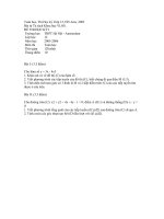
Mixer
The mixer shall consist essentially of:
a)
a stainless steel bowl with a capacity of about 5 litres of the typical shape and size shown in
Figure 1, provided with means by which it can be fixed securely to the mixer frame during mixing
and by which the height of the bowl in relation to the blade and, to some extent, the gap between
blade and bowl can be finely adjusted and fixed;
b)
a stainless steel blade of the typical shape, size and tolerances shown in Figure 1, revolving
about its own axis as it is driven in a planetary movement around the axis of the bowl at
controlled speeds by an electric motor. The two directions of rotation shall be opposite and the
ratio between the two speeds shall not be a whole number.
Blades and bowls shall form sets which shall always be used together.
The gap between blade and bowl shown in Figure 1 shall be checked regularly. The gap of
(3 ± 1) mm refers to the situation when the blade in the empty bowl is brought as close as possible to
the wall. Simple tolerance gauges ('feeler gauges') are useful where direct measurement is difficult.
NOTE
The dimensions marked as approximate on Figure 1 are for the guidance of manufacturers.
The mixer shall operate at the speeds given in Table 2 when mixing the mortar.
Table 2 — Speeds of mixer blade
Low speed
High speed
Rotation
-1
min
140 ± 5
285 ± 10
Planetary movement
–1
min
62 ± 5
125 ± 10
7
EN 196-1:2005 (E)
Dimensions in millimetres
200
30
6±2
16
2
6
180
13
3±
1
6
9
130
8±1
10
27
1
1
28
Key
1
Bowl
2
Blade
Figure 1 — Typical bowl and blade
4.5
Moulds
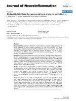
The mould shall consist of three horizontal compartments so that three prismatic specimens
40 mm × 40 mm in cross section and 160 mm in length can be prepared simultaneously.
A typical design is shown in Figure 2.
The mould shall be made of steel with walls approximately 10 mm thick. Each internal side face of the
mould shall be case hardened to a Vickers hardness of at least HV 200, as supplied.
NOTE 1
A minimum Vickers hardness value of HV 400 is recommended.
The mould shall be constructed in such a manner as to facilitate the removal of moulded specimens
without damage. Each mould shall be provided with a machined steel or cast iron baseplate. The
mould, when assembled, shall be positively and rigidly held together and fixed to the baseplate.
8
EN 196-1:2005 (E)
The assembly shall be such that there is no distortion or visible leakage during operation. The
baseplate shall make adequate contact with the table of the compacting apparatus and be rigid
enough not to induce secondary vibrations.
NOTE 2
Moulds and jolting apparatus from different manufacturers may have unrelated external dimensions
and masses, so their compatibility needs to be ensured by the purchaser.
Each part of the mould shall be stamped with identifying marks to facilitate assembly and to ensure
conformity to the specified tolerances. Similar parts of separate mould assemblies shall not be
interchanged.
The assembled mould shall conform to the following requirements.
a)
The internal dimensions and tolerances of each mould compartment shall be as follows:
length:
(160 ± 1) mm;
width:
(40,0 ± 0,2) mm;
depth:
(40,1 ± 0,1) mm.
b)
The flatness tolerance (see ISO 1101) over the whole of each internal side face shall be not
greater than 0,03 mm.
c)
The perpendicularity tolerance (see ISO 1101) for each internal face with respect to the bottom
surface of the mould and the adjacent internal face as datum faces shall be not greater than
0,2 mm.
d)
The surface texture (see EN ISO 1302) of each internal side face shall be not rougher than N8,
as supplied.
Moulds shall be replaced when any one of the specified tolerances is exceeded. The mass of the
mould shall accord with the requirement for the combined mass in 4.6.
In preparing the cleaned mould ready for use, a suitable sealing material shall be used to coat the
outer joints of the mould. A thin film of mould oil shall be applied to the internal faces of the mould.
NOTE 3
suitable.
Some oils have been found to affect the setting of cement; mineral-based oils have been found to be
To facilitate the filling of the mould a tightly fitting metal hopper with vertical walls 20 mm to 40 mm in
height shall be provided. When viewed in plan, the hopper walls shall overlap the internal walls of the
mould by not more than 1 mm. The outer walls of the hopper shall be provided with a means of
location to ensure correct positioning over the mould.
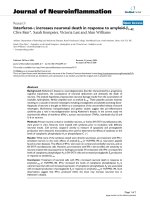
For spreading and striking off the mortar two spreaders and a metal straightedge of the type shown in
Figure 3 shall be provided.
9
EN 196-1:2005 (E)
Dimensions in millimetres
40,1 ± 0,1
160 ± 1
40,0 ± 0,2
40,0 ± 0,2
40,0 ± 0,2
1
Key
1
Striking off direction with sawing motion
Figure 2 — Typical mould
10
EN 196-1:2005 (E)
Dimensions in millimetres
(b) Small spreader
(a). Large spreader
30
2
300
(c) Straightedge
Key
D = Height of hopper
Figure 3 — Typical spreaders and metal straightedge
11
EN 196-1:2005 (E)
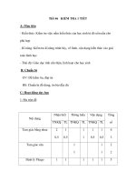
4.6
Jolting apparatus
The jolting apparatus (a typical design is shown in Figure 4) shall conform to the following
requirements.
The apparatus shall consist of a rectangular table rigidly connected by two light arms to a pivot at
nominally 800 mm from the centre of the table. The table shall incorporate at the centre of its lower
face a projecting lug with a rounded face. Beneath the projecting lug shall be a small stop with a plane
upper surface. In the rest position, the common normal through the point of contact of the lug and the
stop shall be vertical. When the lug rests on the stop, the top face of the table shall be horizontal so
that the level of any of the four corners does not deviate from the mean level by more than 1,0 mm.
The table shall have dimensions equal to or greater than those of the mould baseplate, and a plane
machined upper surface. Clamps shall be provided for firm attachment of the mould to the table.
The combined mass of the table, including arms, empty mould, hopper and clamps shall be
(20,0 ± 0,5) kg.
The arms connecting the table assembly to the pivot shall be rigid and constructed of round tubing
with an outside diameter lying in the range 17 mm to 22 mm selected from tube sizes given in
ISO 4200. The total mass of the two arms, including any cross bracing, shall be (2,25 ± 0,25) kg. The
pivot bearings shall be of the ball or roller type and protected from ingress of grit or dust. The
horizontal displacement of the centre of the table as caused by the play of the pivot shall not exceed
1,0 mm.
The lug and the stop shall be made of through-hardened steel of at least HV 500 Vickers hardness
-1
value. The curvature of the lug shall be about 0,01 mm .
In operation, the table is raised by a cam and allowed to fall freely from a height of (15,0 ± 0,3) mm
before the lug strikes the stop.
The cam shall be made of through hardened steel of at least HV 400 Vickers hardness value and its
shaft shall be mounted in ball bearings of such construction that the free fall is always (15,0 ± 0,3) mm.
The cam follower shall be of a construction which ensures minimal wear of the cam. The cam shall be
driven by an electric motor of about 250 W through a reduction gear at a uniform speed of one
revolution per second. A control mechanism and a counter shall be provided which ensures that one
period of jolting of (60 ± 3) s comprises exactly 60 jolts.
The position of the mould on the table shall be such that the longitudinal dimension of the
compartments is in line with the direction of the arms and perpendicular to the axis of rotation of the
cam. Suitable reference marks shall be provided to facilitate the positioning of the mould in such a
way that the centre of the central compartment is directly above the point of impact.
The apparatus shall be firmly mounted on a concrete block of mass of about 600 kg and volume of
3
about 0,25 m and of dimensions giving a suitable working height for the mould. The entire base of
the concrete block shall stand on an elastic pad, e.g. natural rubber, having a suitable isolation
efficiency preventing external vibrations from affecting the compaction.
The base of the apparatus shall be fixed level to the concrete base by anchor bolts and a thin layer of
mortar shall be placed between the base of the apparatus and the concrete base to ensure overall
and vibration free contact.
12
EN 196-1:2005 (E)
Dimensions in millimetres
800
100
2
15,0 ± 0,3
1
3
4
Key
1
Lug
2
Cam follower
3
Cam
4
Stop
Figure 4 — Typical jolting apparatus
4.7
Flexural strength testing apparatus
NOTE
The provision of this apparatus is optional. If only the compressive strength is to be measured,
prisms may be broken using other suitable means which do not subject the prism halves to harmful stresses.
The flexural strength can be measured by using a flexural strength testing machine or by using a
suitable device in a compression testing machine. In either case the apparatus shall conform to the
following requirements:
13
EN 196-1:2005 (E)
The apparatus for the determination of flexural strength shall be capable of applying loads up to 10 kN
with an accuracy of ± 1,0 % of the recorded load in the upper four-fifths of the range being used, at a
rate of loading of (50 ± 10) N/s.
The apparatus shall be provided with a flexure device incorporating two steel supporting rollers of
(10,0 ± 0,5) mm diameter spaced (100,0 ± 0,5) mm apart and a third steel loading roller of the same
diameter placed centrally between the other two. The length of these rollers shall be between 45 mm
and 50 mm. The loading arrangement is shown in Figure 5.
Dimensions in millimetres
40
10,0 ± 0,5
10,0 ± 0,5
47,5 ± 2,5
100,0 ± 0,5
30
160
Front view
Side View
Figure 5 — Arrangement of loading for determination of flexural strength
The three vertical planes through the axes of the three rollers shall be parallel and remain parallel,
equidistant and normal to the direction of the specimen under test. One of the supporting rollers and
the loading roller shall be capable of tilting slightly to allow a uniform distribution of the load over the
width of the specimen without subjecting it to any torsional stresses.
4.8
Compressive strength testing machine
The testing machine for the determination of compressive strength shall be of suitable capacity for the
test (see Note 1): it shall have an accuracy of ± 1,0 % of the recorded load in the upper four-fifths of
the range being used when verified in accordance with EN ISO 7500-1. It shall provide a rate of load
increase of (2 400 ± 200) N/s. It shall be fitted with an indicating device which shall be so constructed
that the value indicated at failure of the specimen remains indicated after the testing machine is
unloaded. This can be achieved by the use of a maximum indicator on a pressure gauge or a memory
on a digital display. Manually operated testing machines shall be fitted with a pacing device to
facilitate the control of the load increase.
The vertical axis of the ram shall coincide with the vertical axis of the machine and during loading the
direction of movement of the ram shall be along the vertical axis of the machine. Furthermore, the
14
EN 196-1:2005 (E)
resultant of the forces shall pass through the centre of the specimen. The surface of the lower
machine platen shall be normal to the axis of the machine and remain normal during loading.
The centre of the upper platen spherical seating shall be at the point of intersection of the vertical
machine axis with the plane of the lower surface of the upper machine platen with a tolerance of
± 1 mm. The upper platen shall be free to align as contact is made with the specimen, but during
loading the relative attitude of the upper and lower platens shall remain fixed.
The testing machine shall be provided with platens made of tungsten carbide, or alternatively through
hardened steel with a Vickers hardness of at least HV 600. These platens shall be at least 10 mm
thick, (40,0 ± 0,1) mm wide and (40,0 ± 0,1) mm long. The flatness tolerance according to ISO 1101,
over the entire contact surface with the specimen shall be not greater than 0,01 mm. The surface
texture according to ISO 1302 shall be not smoother than N3 and not rougher than N6, as supplied.
Alternatively, two auxiliary plates of tungsten carbide, or through hardened steel with a Vickers
hardness of at least HV 600 and at least 10 mm thick and conforming to the requirements for the
platens may be provided. Provision should be made for centring the auxiliary plates with respect to
the axis of the loading system with an accuracy of ± 0,5 mm. Provision should be made for aligning
the auxiliary plates with a tolerance not greater than ± 0,5 mm from the centre of each other.
Where there is no spherical seating in the testing machine or where the spherical seating is blocked,
or where the diameter of the spherical seating is greater than 120 mm, a jig conforming to 4.9 shall be
used.
NOTE 1
The testing machine may be provided with two or more load ranges. The highest value of the lower
range should be approximately 1/5 of the highest value of the next higher range.
NOTE 2
The machine should be provided with an automatic method for adjusting the rate of loading and with
equipment for recording the results.
NOTE 3
The spherical seating of the machine may be lubricated to facilitate adjustment on contact with the
specimen but only to such an extent that movement of the platen cannot take place under load during the test.
Lubricants which are effective under high pressure are not suitable.
NOTE 4
The terms 'vertical', 'lower' and 'upper' refer to conventional testing machines which are normally
aligned in the vertical axis. However, machines whose axis is not vertical are also permitted.
4.9
Jig for compressive strength testing machine
When 4.8 requires the use of a jig (see Figure 6) it shall be placed between the platens of the
machine to transmit the load of the machine to the compression surfaces of the mortar specimen.
A lower plate shall be used in this jig and it can be incorporated in the lower platen. The upper platen
receives the load from the upper platen of the machine through an intermediate spherical seating.
This seating forms part of an assembly which shall be able to slide vertically without appreciable
friction in the jig guiding its movement. The jig shall be kept clean and the spherical seating shall be
free to move in such a way that the platen will accommodate itself initially to the shape of the
specimen and then remain fixed during the test. All requirements stated in 4.8 apply equally when a
jig is used.
NOTE 1
The spherical seating of the jig may be lubricated but only to such an extent that movement of the
platen cannot take place under load during the test. Lubricants which are effective under high pressure are not
suitable.
NOTE 2
It is desirable that the assembly should return automatically to its initial position after crushing the
specimen.
15
EN 196-1:2005 (E)
4.10 Balance
Balance, capable of weighing to an accuracy of ± 1 g.
4.11 Timer
Timer, capable of measuring to an accuracy of ± 1 s.
4
5
3
1
2
6
7
10
8
9
11
Key
1
Ball bearings
2
Sliding assemble
3
Return spring
4
Spherical seating of machine
5
Upper platen of machine
6
Spherical seating of the jig
7
Upper platen of the jig
8
Specimen
9
Lower platen of the jig
10
Jig
11
Lower platen of the machine
Figure 6 — Typical jig for compressive strength testing
16
EN 196-1:2005 (E)
5
Mortar constituents
5.1
5.1.1
Sand
General
CEN Standard sands, which are produced in various countries, shall be used to determine the
strength of cement in accordance with this document. 'CEN Standard sand, EN 196-1' shall conform
to the requirements stated in 5.1.3. Producers of CEN Standard sand shall apply verification testing
which shall be inspected under the authority of a certification body.
In view of the difficulties of characterising CEN Standard sands completely they shall be validated
against the CEN Reference sand described in 5.1.2 by means of certification and verification testing,
as described in Clause 11.
5.1.2
CEN Reference sand
The CEN Reference sand, of which a limited stockpile is maintained as reference material, is a natural,
siliceous sand consisting of rounded particles and has a silica content of at least 98 %.
Its particle size distribution lies within the limits given in Table 3.
Table 3 — Particle size distribution of the CEN Reference sand
Square mesh size (mm)
Cumulative sieve residue (%)
2,00
1,60
1,00
0,50
0,16
0,08
0
7±5
33 ± 5
67 ± 5
87 ± 5
99 ± 1
NOTE
Information on the CEN Reference sand may be obtained from Normensand GmbH, D-59269
Beckum, Germany.
5.1.3
CEN Standard sand
CEN Standard sand shall comply with the particle size distribution specified in 5.1.2 as determined by
sieve analysis on a representative sample of sand of total mass not less than 1 345 g. Sieving shall
be continued until the amount of sand passing through each sieve is less than 0,5 g/min.
The moisture content shall be less than 0,2 % determined as the loss of mass of a representative
sample of sand after drying at 105 °C to 110 °C to constant mass and expressed as a percentage by
mass of the dried sample.
During production these determinations shall be carried out at least once a day. These requirements
are insufficient to ensure that the CEN Standard sand gives equivalent performance to the CEN
Reference sand. Such equivalence shall be initiated and maintained by the validation testing
described in Clause 11.
CEN Standard sand shall be pre-packed in bags with a content of (1 350 ± 5) g; the type of material
used for the bags shall have no effect on the results of the strength testing and the contents of each
bag shall comply with the particle size distribution specified in 5.1.2.
NOTE
CEN Standard sand should be carefully stored to prevent damage or contamination, particularly with
moisture, prior to use.
17
EN 196-1:2005 (E)
5.2
Cement
The cement to be tested shall be exposed to ambient air for the minimum time possible. When it is to
be kept for more than 24 h between sampling and testing, it shall be stored in completely filled and
airtight containers made from a material which does not react with cement.
The laboratory sample shall be homogenised, by machine or other means as described in EN 196-7,
before taking sub-samples for testing.
5.3
Water
Distilled, or deionised, water shall be used for validation testing. For other tests, drinking water may
be used. In the case of dispute distilled or deionised water shall be used.
6
6.1
Preparation of mortar
Composition of mortar
The proportions by mass shall be one part of the cement (5.2), three parts of CEN Standard sand
(5.1), and one half part of water (5.3) (water/cement ratio 0,50).
Each batch for three test specimens shall consist of (450 ± 2) g of cement, (1 350 ± 5) g of sand and
(225 ± 1) g of water.
6.2
Mixing of mortar
Weigh the cement and water by means of the balance (4.10). When water is added by volume it shall
be dispensed with an accuracy of ± 1 ml. Mix each batch of mortar mechanically using the mixer (4.4).
The timing of the various mixing stages refers to the times at which mixer power is switched on/off
and shall be maintained within ± 2 s.
The mixing procedure shall be as follows:
a)
place the water and the cement into the bowl, taking care to avoid loss of water or cement;
b)
immediately the water and cement are brought into contact start the mixer at the low speed (see
Table 2) whilst starting the timing of the mixing stages. In addition, record the time to the nearest
minute, as ‘zero time’. After 30 s of mixing, add the sand steadily during the next 30 s. Switch the
mixer to the high speed (see Table 2) and continue the mixing for an additional 30 s;
NOTE 1
‘Zero time’ is the point from which the times for demoulding specimens (see 8.2) and for determining
strength (see 8.4) are calculated.
c)
stop the mixer for 90 s. During the first 30 s, remove by means of a rubber or plastics scraper the
mortar adhering to the wall and bottom part of the bowl and place in the middle of the bowl;
d)
continue the mixing at the high speed for 60 s.
NOTE 2
Normally these mixing operations are carried out automatically. Manual control of these operations
and timings may be used.
18
EN 196-1:2005 (E)
7
Preparation of test specimens
7.1
Size of specimens
The test specimens shall be 40 mm × 40 mm × 160 mm prisms.
7.2
Moulding of test specimens
Mould the specimens immediately after the preparation of the mortar. With the mould and hopper
firmly clamped to the jolting table, introduce, using a suitable scoop, in one or more increments, the
first of two layers of mortar (each about 300 g) into each of the mould compartments, directly from the
mixing bowl.
Spread the layer uniformly using the large spreader (see Figure 3), held almost vertically with its
shoulders in contact with the top of the hopper and drawn forwards and backwards once along each
mould compartment. Then compact the first mortar layer using 60 jolts of the jolting apparatus (4.6).
Introduce the second layer of mortar, ensuring that there is a surplus of mortar, level with the small
spreader (see Figure 3) and compact the layer with a further 60 jolts.
Lift the mould gently from the jolting table and remove the hopper. Immediately strike off the excess
mortar with the metal straightedge (see Figure 3), held almost vertically but inclined in the direction of
striking. Move slowly pulling with a transverse sawing motion once in each direction. Repeat this
striking off procedure with the straightedge held at a more acute angle to smooth the surface.
NOTE
The number of sawing motions and the angle of the straightedge will depend on the consistency of
the mortar; stiffer mortars will require more sawing motions and a more acute angle; a smaller number of
transverse sawing motions are required for smoothing than for striking off (see Figure 2).
Wipe off the mortar left on the perimeter of the mould as a result of the striking-off.
Label or mark the moulds for identification purposes.
8
Conditioning of test specimens
8.1
Handling and storage before demoulding
Place a plate of glass, steel or other impermeable material which does not react with cement of
approximate size 210 mm × 185 mm × 6 mm on the mould.
NOTE
In the interest of safety, ensure that any glass plates used have ground edges.
Place each covered mould, without delay, on a horizontal base in the moist air room or cabinet
(see 4.1). The moist air shall have access to all sides of the mould. Moulds shall not be stacked one
upon the other. Each mould shall be removed from storage at its appropriate time for demoulding.
8.2
Demoulding of specimens
Carry out demoulding taking care not to damage specimens. Plastics or rubber hammers, or devices
specially made, can be used for demoulding. Carry out demoulding, for 24 h tests, not more than
20 min before the specimens are tested. Carry out demoulding, for tests at ages greater than 24 h,
between 20 h and 24 h after moulding.
NOTE 1
Demoulding may be delayed by 24 h if the mortar has not acquired sufficient strength at 24 h to be
handled without risk of damage. Any delay in demoulding should be recorded in the test report.
19
EN 196-1:2005 (E)
Keep the demoulded specimens selected for testing at 24 h (or at 48 h when delayed demoulding was
necessary) covered by a damp cloth until tested. Suitably mark specimens selected for curing in water
for identification later, e.g. by water-resistant ink or crayon.
NOTE 2
As a check on the mixing and compacting operations and air content of the mortar, it is
recommended that the specimens from each mould be weighed.
8.3
Curing of specimens in water
Submerge the marked specimens without delay in a convenient manner, either horizontally or
vertically, in water at (20,0 ± 1,0) °C in the containers. With horizontal storage, keep vertical faces as
cast vertical.
Place the specimens on the gratings (see 4.1) and keep them apart from each other so that the water
has free access to all six faces of the specimens. At no time during storage shall the spaces between
the specimens or the depth of water above the upper faces of the specimens be less than 5 mm.
Unless it has been established that the composition of the cement to be tested does not influence the
strength development of other cements under test, separate storage shall be provided; cements
known to contain more than 0,1 % chloride ion shall be stored separately.
Use tap water for initial filling of the containers and for occasional topping up to maintain a reasonably
constant level. During storage of the specimens, not more than 50 % of the water shall be replaced at
any one time.
The installation shall ensure uniform storage temperature; if a system of circulation within the storage
container is used the flow rate shall be as low as possible and not cause visible turbulence.
Remove the specimens required for testing at any particular age (other than 24 h, or 48 h in cases of
delayed demoulding) from the water not more than 15 min before the test is carried out. Remove any
deposit on the test faces. Cover the specimens with a damp cloth until tested.
8.4
Age of specimens for strength tests
Calculate the age of specimens as that from zero time (see 6.2). Carry out strength tests at the
different ages within the following limits:
24 h ± 15 min
48 h ± 30 min
72 h ± 45 min
7d±2h
≥ 28 d ± 8 h.
9
9.1
Testing procedures
Flexural strength
Use the three-point loading method with one of the types of apparatus described in 4.7.
Place the prism in the apparatus (4.7) with one side face on the supporting rollers and with its
longitudinal axis normal to the supports. Apply the load vertically by means of the loading roller to the
opposite side face of the prism and increase it smoothly at the rate of (50 ± 10) N/s until fracture.
20
EN 196-1:2005 (E)
Keep the prism halves covered with a damp cloth until tested in compression.
Calculate the flexural strength, Rf, in megapascals from:
Rf =
1,5 × F f × l
b
3
(1)
where
9.2
Rf
is the flexural strength, in megapascals;
b
is the side of the square section of the prism, in millimetres;
Ff
is the load applied to the middle of the prism at fracture, in newtons;
l
is the distance between the supports, in millimetres.
Compressive strength
Carry out the test on halves of the prism broken either as described in 9.1 or by using suitable means
which do not subject the prism halves to harmful stresses.
Test each prism half by loading its side faces using the equipment described in 4.8 and 4.9.
Centre the prism halves laterally to the platens of the machine within ± 0,5 mm, and longitudinally
such that the end face of the prism overhangs the platens or auxiliary plates by about 10 mm.
Increase the load smoothly at the rate of (2 400 ± 200) N/s over the entire load application until
fracture.
Where the load increase is regulated by hand, care should be taken when making adjustment for the
decrease of the loading rate near the fracture load as this can significantly affect the result.
Calculate the compressive strength Rc in megapascals from:
Rc =
Fc
1600
(2)
where
Rc
is the compressive strength, in megapascals;
Fc
is the maximum load at fracture, in newtons;
1 600 is the area of the platens or auxiliary plates (40 mm × 40 mm), in square millimetres.
10 Results
10.1 Flexural strength
10.1.1 Calculation and expression of test results
Calculate the flexural strength test result as the arithmetic mean of the three individual results, each
expressed at least to the nearest 0,1 MPa, obtained from a determination made on a set of three
prisms.
21
EN 196-1:2005 (E)
Express the arithmetic mean to the nearest 0,1 MPa.
10.1.2 Reporting of results
Record all individual results. Report the calculated mean.
10.2 Compressive strength
10.2.1 Calculation and expression of test results
Calculate the compressive strength test result as the arithmetic mean of the six individual results,
each expressed at least to the nearest 0,1 MPa, obtained from the six determinations made on a set
of three prisms.
If one result within the six individual results varies by more than ± 10 % from the mean, discard this
result and calculate the arithmetic mean of the five remaining results. If one result within the five
remaining results varies by more than ± 10 % from their mean, discard the set of results and repeat
the determination.
Express the arithmetic mean to the nearest 0,1 MPa.
10.2.2 Reporting of results
Record all individual results. Report the calculated mean and whether any result has been discarded
in accordance with 10.2.1.
10.2.3 Estimates of the precision of the method for compressive strength
10.2.3.1
Short-term repeatability
Short-term repeatability of the method for compressive strength testing gives the closeness of
agreement between test results obtained on nominally identical samples of cement, using the same
CEN Standard sand, tested in the same laboratory by the same operator using the same equipment
within short intervals of time.
In the case of 28 day compressive strength, the short-term repeatability for “normal performance”
achievable under the above conditions, should be less than 2,0 % when expressed as the coefficient
of variation.
NOTE
Experience has indicated that better performance is achievable and can be routinely met in some
laboratories. It corresponds to a value of 1 % for short-term repeatability, when expressed as the coefficient of
variation.
Short-term repeatability is a measure of the precision of the test method when used for validation
testing of CEN Standard sand and alternative compaction equipment.
10.2.3.2
Long-term repeatability
Long-term repeatability of the method for compressive strength testing, gives the closeness of
agreement between test results obtained from frequent testing of different samples taken from the
same homogenised sample of cement, tested in the same laboratory, under the following conditions:
possibly different operators, possibly different equipment, same CEN Standard sand and over long
time periods (up to one year).
In the case of 28 day compressive strength, the long-term repeatability for “normal performance”
achievable under the above conditions, should be less than 3,5 % when expressed as the coefficient
of variation.
22
EN 196-1:2005 (E)
NOTE
Experience has indicated that better performance is achievable and can be routinely met in some
laboratories. It corresponds to a value of 2,5 % for long term repeatability, when expressed as the coefficient of
variation.
Long-term repeatability is a measure of the precision of the test method when used for the autocontrol
testing of cement or the monthly verification testing of CEN Standard sand and for assessing the
maintenance of the laboratory’s precision over time.
10.2.3.3
Reproducibility
Reproducibility of the method for compressive strength testing gives the closeness of agreement
between test results obtained on nominally identical samples of cement tested in different laboratories
under the following conditions: different operators, different equipment, possibly different CEN
Standard sands and possibly at different times.
In the case of 28 d compressive strength, the reproducibility, between laboratories achieving “normal
performance” under the above conditions, should be less than 4,0 % when expressed as the
coefficient of variation.
NOTE
Experience has indicated that better performance is achievable and can be routinely met in some
laboratories. It corresponds to a value of 3 % for reproducibility, when expressed as the coefficient of variation.
Reproducibility is a measure of the precision of the test method when used for evaluation of
conformity of cement or CEN Standard sand.
11 Validation testing of CEN Standard sand and of alternative compaction
equipment
11.1 General
A CEN Standard sand complying with 5.1.3 or an alternative compaction equipment may be used,
according to Clause 3, provided that they have been shown to give cement strength results which do
not differ significantly from those obtained using the CEN Reference sand (5.1.2) or the reference
jolting apparatus (4.6) and procedure, respectively.
This clause describes the conditions under which CEN Standard sands and alternative compaction
equipment can be validated. Validation shall be provided by a certification body and shall be based on
the results of tests carried out by a testing laboratory appointed by the certification body.
NOTE
Appointed testing laboratories should participate in proficiency testing programmes to ensure that
validation testing is against comparable testing levels.
The test methods which are described and shall be applied are based on comparisons of compressive
strength test results at the age of 28 d.
11.2 Validation testing of CEN Standard sand
11.2.1 Principle
Validation testing of CEN Standard sand comprises:
a)
certification testing carried out under the authority of a certification body;
b)
verification testing carried out by the producer of sand.
Certification testing of CEN Standard sand is described in 11.2.2. It includes an initial certification
testing (11.2.2.1) and an annual confirmation testing (11.2.2.2). Provided that the requirements in
23