E560 web server release11
Bạn đang xem bản rút gọn của tài liệu. Xem và tải ngay bản đầy đủ của tài liệu tại đây (11.94 MB, 94 trang )
RTU500 series
RTU500 series Remote Terminal Unit
User manual
Users Guide for RTU500 series Web server
RTU500 series Remote Terminal Unit
Revision
Revision
Document identity:
Revision:
Date:
0
03/2013
1
02/2014
2
1KGT 150 802 V002 1 - ABB AG
08/2014
1KGT 150 802 V002 1
Changes:
New document for Release 11.0
Update for Release 11.1
Chapter ‘Change language of Web server’ added
Update for Release 11.3
Chapter ‘PPP Installation’ enhanced for Windows 7
New Layout
RTU500 series Remote Terminal Unit
Contents
Contents
1
Introduction.................................................................................................................... 1-1
1.1
Preface................................................................................................................1-1
1.2
Structure of this document................................................................................. 1-1
1.3
References.......................................................................................................... 1-1
1.4
Access to the Web server.................................................................................. 1-1
1.5
Presentation of the RTU500 series Web Pages.................................................. 1-4
2
System Diagnosis...........................................................................................................2-1
3
Network Tree..................................................................................................................3-1
4
Hardware Tree................................................................................................................4-1
5
4.1
General Overview................................................................................................4-1
4.2
Board Diagnosis................................................................................................. 4-1
4.3
System Signaling, Time Administration............................................................... 4-3
Archive Information.........................................................................................................5-1
5.1
General Overview................................................................................................5-1
5.2
Process Archives................................................................................................ 5-1
5.3
File Archive......................................................................................................... 5-2
5.4
Conversion Properties.........................................................................................5-3
5.5
Security Event Archive........................................................................................ 5-6
6
Starting the Integrated HMI............................................................................................6-1
7
Configuration Files..........................................................................................................7-1
8
Firmware Files................................................................................................................ 8-1
9
8.1
Update firmware files.......................................................................................... 8-1
8.2
License Upgrade.................................................................................................8-2
8.3
Change language of the web server................................................................... 8-2
Help Page...................................................................................................................... 9-1
9.1
10
11
System Help Page.............................................................................................. 9-1
Administration...............................................................................................................10-1
10.1
Overview........................................................................................................... 10-1
10.2
Edit User Accounts...........................................................................................10-1
10.2.1
Security Policies...............................................................................10-2
10.2.2
User Accounts / Passwords.............................................................10-4
10.2.3
User Roles....................................................................................... 10-5
10.3
Download / Upload Password Files.................................................................. 10-8
10.4
Logging and Debugging................................................................................... 10-8
10.5
Password File Harmonization............................................................................10-9
PPP Installation............................................................................................................ 11-1
ABB AG - 1KGT 150 802 V002 1 | I
RTU500 series Remote Terminal Unit
Contents
12
13
II | 1KGT 150 802 V002 1 - ABB AG
11.1
Windows XP..................................................................................................... 11-1
11.2
Windows 7......................................................................................................11-22
USB RNDIS Driver Installation...................................................................................... 12-1
12.1
Windows XP..................................................................................................... 12-1
12.2
Windows 7........................................................................................................12-7
Glossary....................................................................................................................... 13-1
RTU500 series Remote Terminal Unit
Introduction
Preface
1 Introduction
1.1
Preface
The document describes the requirements and installation steps needed to build up a full RTU500
series engineering environment. The base configuration of the Operating System Microsoft Windows
XP Professional and the tools required for the engineering process are described. For Microsoft
Windows 7 similar configuration actions are required. System requirement are defined in chapter
Chapter 9.1 in figure "Fig. 26: Page for general information and pre-requisitions" .
1.2
Structure of this document
This document is divided in two main parts:
The first part describes the RTU500 series Web server functionality:
•
•
•
•
•
•
•
System diagnosis functionality
The Network Tree
Process diagnosis functionality (Hardware Tree)
Archive Information
Loading of RTU configuration files
Loading of RTU firmware files
Administration of the system
The second part includes the installation and configuration of the environment.
•
•
•
•
•
1.3
PPP Installation
USB Installation
Establishing the connection
Network configuration
The hardware required for the connection
References
Additional Information is available in the documents:
[1]
[2]
1.4
1KGT 150 722
1KGT 150 801
Security Deployment Guide Line
RTUtil500 User's Guide Release 11
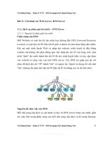
Access to the Web server
The integrated Web server is accessed by the Internet Explorer, using the IP address of one of the
Ethernet Interfaces of the RTU Communication Unit. The access to the Web server must be enabled
in the configuration tool RTUtil500 [2] (see figure "Fig. 1: Starting the Web server with http").
ABB AG - 1KGT 150 802 V002 1 | 1-1
RTU500 series Remote Terminal Unit
Introduction
Access to the Web server
Figure 1: Starting the Web server with http
A secure connection is enabled by using https (see "Fig. 2: Access to the Web server using https").
Because the server certificates used by the RTU are self-signed, the certificates must be installed
on the Web client, in order to avoid further warning messages.
For more details about the handling of self-signed certificates see [1].
1-2 | 1KGT 150 802 V002 1 - ABB AG
RTU500 series Remote Terminal Unit
Introduction
Access to the Web server
Figure 2: Access to the Web server using https
After successful connection the used must log into the Web server by 'user name' and 'password'.
At the end the used must log off again. See "Fig. 3: Log in and log off" / 1 and 2.
Figure 3: Log in and log off
ABB AG - 1KGT 150 802 V002 1 | 1-3
Introduction
Presentation of the RTU500 series Web Pages
RTU500 series Remote Terminal Unit
After a configurable time of inactivity (3), the user will be logged off by the system.
If some of the error messages of the Web server are more or less general, but not containing detailed
information, adjust the Internet Explorer settings as follows (see "Fig. 4: Internet Explorer Settings"):
-> Extras
-> Internet Options
-> Advanced
-> DISABLE 'Show friendly HTTP error messages'
Figure 4: Internet Explorer Settings
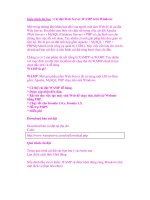
1.5
Presentation of the RTU500 series Web Pages
All the pages used to in the RTU Web Server are structured with frames:
• Main menu frame (1)
• Presentation frame (2)
• Selection frame (3)
1-4 | 1KGT 150 802 V002 1 - ABB AG
RTU500 series Remote Terminal Unit
Introduction
Presentation of the RTU500 series Web Pages
Figure 5: Structure of the Web server pages
The 'main menu frame' (1) is fixed during runtime, but depending on the configuration of the RTU.
The 'presentation frame' (2) depends also on the configuration of the RTU, but will not be updated,
as long as the frame is shown.
The 'selection frame' (3)
• will be updated cyclically (approximately every 2 seconds)
• must be updated on demand by the user.
ABB AG - 1KGT 150 802 V002 1 | 1-5
Introduction
Presentation of the RTU500 series Web Pages
1-6 | 1KGT 150 802 V002 1 - ABB AG
RTU500 series Remote Terminal Unit
RTU500 series Remote Terminal Unit
System Diagnosis
2 System Diagnosis
The system diagnosis pages give information about the actual state of the RTU.
The diagnosis information can be filtered in different areas (see "Fig. 6: System diagnosis page,
general view"):
•
•
•
•
•
All
System
Activies
I/O boards
Connected I/O devices
Figure 6: System diagnosis page, general view
ABB AG - 1KGT 150 802 V002 1 | 2-1
System Diagnosis
2-2 | 1KGT 150 802 V002 1 - ABB AG
RTU500 series Remote Terminal Unit
RTU500 series Remote Terminal Unit
Network Tree
3 Network Tree
The Network Tree shows all external connections of the RTU Node. The representation is the same
as in the configuration tool RTUtil500 (see "Fig. 7: The Network Tree").
Figure 7: The Network Tree
By selecting the top node link RTU, it is possible to select another communication unit of the RTU
system (see "Fig. 8: Select another communication unit" / 1).
ABB AG - 1KGT 150 802 V002 1 | 3-1
RTU500 series Remote Terminal Unit
Network Tree
Figure 8: Select another communication unit
The user has to log into the selected communication unit (2), and has to log out at the end of the
session (3).
It is also possible to log into subordinated devices (see "Fig. 7: The Network Tree", Sub 1, Sub
2), if the subordinated device is 'active' (SEV #024) and 'operable' (SEV #048). Log in / Log out
procedure see above.
If the user has connected to another communication unit of the same RTU, or to a communication
unit of a connected subordinated device by using the 'Network Tree', the representation of the other
trees will change (see "Fig. 9: Representation changes" as an example).
3-2 | 1KGT 150 802 V002 1 - ABB AG
RTU500 series Remote Terminal Unit
Network Tree
Figure 9: Representation changes
ABB AG - 1KGT 150 802 V002 1 | 3-3
Network Tree
3-4 | 1KGT 150 802 V002 1 - ABB AG
RTU500 series Remote Terminal Unit
RTU500 series Remote Terminal Unit
Hardware Tree
General Overview
4 Hardware Tree
4.1
General Overview
The Hardware tree page gives information about the configuration of the RTU and about the actual
values of the process objects according the configuration in RTUtil500 (see "Fig. 10: Hardware tree
pages").
It can be selected the data points of the I/O module via mouse click in the middle of the window.
The channel number, process object ID and the actual value are shown in the right window. The
channel value and the status information are updated cyclically.
Figure 10: Hardware tree pages
By selecting a binary or analoge output module, it is possible to perform commands directly to the
connected primary process (see "Fig. 10: Hardware tree pages").
ADVICE
The output control function is only for test purposes during commissioning phase. It is not allowed
to use this function to send commands to an active process.
In order to perform commands out of the Web server, the following pre-conditions must be fulfilled:
• The debugging option must be generally enabled (see chapter Chapter 10.2.1)
• The used must have the privileges to perform commands (see chapter Chapter 10.2.3)
• The debugging option must be temporary enabled (see chapter Chapter )
4.2
Board Diagnosis
By selecting a communication unit in the hardware tree, the user will get information about the state
of this unit.
ABB AG - 1KGT 150 802 V002 1 | 4-1
RTU500 series Remote Terminal Unit
Hardware Tree
Board Diagnosis
Figure 11: State of a communication unit
By selecting a serial communication line, connected to a communication unit, the user will get static
and dynamic information about this line.
Figure 12: State of a serial communication line
4-2 | 1KGT 150 802 V002 1 - ABB AG
RTU500 series Remote Terminal Unit
4.3
Hardware Tree
System Signaling, Time Administration
System Signaling, Time Administration
The state of the system is represented by 'System Events', which are shown by selecting the top
level node RTU (see "Fig. 13: System Signaling, Time Administration") (1+2).
Figure 13: System Signaling, Time Administration
At the end of the 'system signaling page' the time of the RTU can be set manually (see "Fig. 13:
System Signaling, Time Administration") (2+3).
This feature is available/visible only if:
•
•
•
•
the debugging option is generally enabled (see chapter Chapter 10.2.1)
the used has the privileges to perform commands (see chapter Chapter 10.2.3)
the debugging option is temporary enabled (see chapter Chapter )
the user is connected to a CMU in the state 'Time Administration Master'
The time can be set:
• manually by a pull down menu
• according to the time of the connected PC
ABB AG - 1KGT 150 802 V002 1 | 4-3
Hardware Tree
System Signaling, Time Administration
4-4 | 1KGT 150 802 V002 1 - ABB AG
RTU500 series Remote Terminal Unit
RTU500 series Remote Terminal Unit
Archive Information
General Overview
5 Archive Information
5.1
General Overview
Archives are stored on the memory card of a communication unit. RTU500 series supports following
archives:
• Process Archives (see chapter Chapter 5.2)
• File Archives (see chapter Chapter 5.3)
• Security Event Archive (see chapter Chapter 5.5)
The archive size can be configured with RTUtil500 [2].
Figure 14: Archive Configuration
The arrow buttons enable you to browse through the data archive.
With the disk button the currently selected archive can be downloaded.
5.2
Process Archives
Process archives are available for:
• Events and Indications
• Measurements
• Pulse Counter Values
ABB AG - 1KGT 150 802 V002 1 | 5-1
RTU500 series Remote Terminal Unit
Archive Information
File Archive
Figure 15: Event and Indications
5.3
File Archive
Within RTU500 series Webserver there is an own page for the file archive. This page shows the files
in a variable structure, configurable by the user. This page is also used for the file transfer of the
files to the workplace PC.
The menu bar on top of the table contains (from left to right) a pushbutton to open a dialog for the
conversion properties, a pushbutton to navigate in the folder, and a pushbutton to refresh the page.
Figure 16: Pushbutton of the file manager
The left hand part of the table shows all available directories within the RTU, the right hand part
shows the directory structure of the local PC.
5-2 | 1KGT 150 802 V002 1 - ABB AG
RTU500 series Remote Terminal Unit
Archive Information
Conversion Properties
Figure 17: File Archive Manager, main page
5.4
Conversion Properties
For each directory displayed in the Archive File Manager it is possible to configure a target directory
and a target filename. Entered values will be saved on the local PC for the current logged in user,
if the operation system supports user accounts. Therefore the entered values have only be entered
once, even if the web-browser or the RTU will be restarted.
The field ‘Target directory name’ contains the name of the target directory on a local PC. This entry
is only necessary for automatic download of files, initiated by the local PC.
In the field ‘Target Filename’ the resulting name of the selected file after copying to the local PC can
be entered. If no value entered, a default name will be used.
In the field ‘Conversion Call’ is necessary for meter data only.
ABB AG - 1KGT 150 802 V002 1 | 5-3
RTU500 series Remote Terminal Unit
Archive Information
Conversion Properties
Figure 18: Conversion properties
Both values are strings, which supports wildcard usage. With the wildcards it is possible to define
a target filename or a conversion call for all files in a directory.
Wildcards starts and ends always with the percentage-sign % (e.g. %nameoffile% ). While processing, wildcards will be replaced by the corresponding values of the selected file.
The following wildcards are supported by the RTU archive manager:
Wildcard
Meaning
nameoffile
Name of File
revindex
Directory entries, that cannot be differed by name of file or creation time, have different
revision indices.
Revision index starts always with ‘a’ and will be incremented
cyear2
Year of creation time in format YY.
Example: Year ‘2003’ will be displayed as ‘03’
Range: 0 – 99
Table 1: Wildcards
5-4 | 1KGT 150 802 V002 1 - ABB AG
RTU500 series Remote Terminal Unit
Archive Information
Conversion Properties
Wildcard
Meaning
cmonth
Month of creation time in format MM.
Example: Month ‘December’ will be displayed as ‘12’
Range: 1 – 12
cdayofmonth
Day of month of creation time in format DD.
Range: 1 – 31
chourofday
Hour of creation time in format HH.
Range: 0 – 23
cminute
Minute of creation time in format MM.
Range: 0 – 59
csecond
Second of creation time in format XX.
Range: 0 – 59
syear
Year of storage time in format YY.
Example: Year ‘2003’ will be displayed as ‘03’
Range: 0 – 99
smonth
Month of storage time in format MM.
Example: Month ‘December’ will be displayed as ‘12’
Range: 1 – 12
sdayofmonth
Day of month of storage time in format DD.
Range: 1 – 31
shourofday
Hour of storage time in format HH.
Range: 0 - 24
sminute
Minute of storage time in format MM.
Range: 0 – 59
ssecond
Second of storage time in format XX.
Range: 0 – 59
workingdir
The path of the directory selected on the local PC selected in the right-panel.
parentdir
Name of the parent directory the selected file is located in as displayed in the header
of the dialog.
targetfilename
The result of the processed target filename string. That means all wildcards are already replaced by the corresponding values of the selected file.
Table 1: Wildcards
Wildcards which are numbers can be extended to a fixed number of characters by adding a ‘0’ (Zero)
followed by the number of characters of the item.
Example:
Value: Creation time 4 minutes, 2 digits with leading ‘0’, if necessary.
Wildcard: %02cminute%
Result: ’04’
Value Creation year 1998, only the last two digits
Wildcard: %cyear2%
Result: ’98’
ABB AG - 1KGT 150 802 V002 1 | 5-5