Slide điện tử từ trường lecture 12 bjts differential pair
Bạn đang xem bản rút gọn của tài liệu. Xem và tải ngay bản đầy đủ của tài liệu tại đây (1.32 MB, 40 trang )
Lecture 12
BJT’s Differential Pair
1
Microelectronic Circuits by
Meiling CHEN
CuuDuongThanCong.com
/>
topics
• Ideal characteristics of differential
amplifier
–
–
–
–
Input differential resistance
Input common-mode resistance
Differential voltage gain
CMRR
• Non-ideal characteristics of differential
amplifier
– Input offset voltage
– Input biasing and offset current
• Differential Amplifier with active load
2
Microelectronic Circuits by
Meiling CHEN
CuuDuongThanCong.com
/>
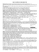
Differential pair
Figure 7.12 The basic BJT differential-pair configuration.
3
Microelectronic Circuits by
Meiling CHEN
CuuDuongThanCong.com
/>
Common mode operation
Q Q1 = Q2
∴ vB1 = vB 2 = vCM
⇒ iE1 = iE 2
I
=
2
⇒ vC1 = vC 2 = VCC
I
− α RC
2
vC1 − vC 2 = 0
Reject common mode input
Figure 7.13 Different modes of operation of the BJT differential pair: (a) The differential pair with a common-mode input signal vCM.
4
Microelectronic Circuits by
Meiling CHEN
CuuDuongThanCong.com
/>
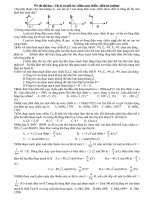
The differential pair with a “large” differential input
signal
(1)VB1 >> VB 2
VB1 = +1V , VB 2 = 0
Q1 on → VE1 = 0.3V = VE 2 → Q2
off
VC1 = VCC − αIRC , VC 2 = VCC
VC1 − VC 2 = −αIRC
Figure 7.13 Different modes of operation of the BJT differential pair:. (b) The differential pair with a “large” differential input signal.
5
Microelectronic Circuits by
Meiling CHEN
CuuDuongThanCong.com
/>
(2)VB1 << VB 2
VB1 = −1V , VB 2 = 0
Q2
+
0.7
on → VE 2 = −0.7V = VE 2 → Q1 off
VC 2 = VCC − αIRC , VC1 = VCC
VC1 − VC 2 = αIRC
−
Figure 7.13 (Continued) (c) The differential pair with a large differential input signal of polarity opposite to that in .
6
Microelectronic Circuits by
Meiling CHEN
CuuDuongThanCong.com
/>
(3)VB1 > VB 2
VB1 = small , VB 2 = 0
I
I
I E1 = + ΔI , I E 2 = − ΔI
2
2
I
VC1 = VCC − α RC − αΔIRC
2
I
VC 2 = VCC − α RC + αΔIRC
2
VC1 − VC 2 = vo = −2αΔIRC
⇒ vo = f (ΔI )
Figure 7.13 (Continued) (d) The differential pair with a small differential input signal vi. Note that we have assumed the bias current source I
to be ideal (i.e., it has an infinite output resistance) and thus I remains constant with the change in vCM.
7
Microelectronic Circuits by
Meiling CHEN
CuuDuongThanCong.com
/>
Exercise 7.7
let α ≈ 1, vBE = 0.7V
find vE , vC1 and vC 2
5 − 0.7
I=
= 4.3mA
1k
+
0.7
−
8
Microelectronic Circuits by
Meiling CHEN
CuuDuongThanCong.com
/>
Large signal operation
iE 1 =
IS
e ( vB1 −vE ) / VT
iE 2 =
IS
e ( vB 2 −vE ) / VT
α
α
iE 1
= e ( vB1 −vB 2 ) / VT
iE 2
iE1
1
=
iE1 + iE 2 1 + e ( vB 2 −vB1 ) / VT
iE 2
1
=
iE1 + iE 2 1 + e ( vB1 −vB 2 ) / VT
iE 1 + iE 2 = I
iE 1 =
iE 2
I
1 + e −vid / VT
I
=
1 + e vid / VT
9
Microelectronic Circuits by
Meiling CHEN
CuuDuongThanCong.com
/>
iC1
1
≈
I 1 + e −vid / VT
1 + e −vid / VT
iC 2
I
1
=
⇒
≈
vid / VT
I 1 + e vid / VT
1+ e
I
iE 1 =
iE 2
⇒
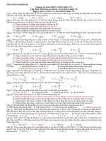
How to enhance linear
region?
Figure 7.14 Transfer characteristics of the BJT differential pair of Fig. 7.12 assuming α . 1.
10
Microelectronic Circuits by
Meiling CHEN
CuuDuongThanCong.com
/>
Re ↑→vE ↑→vBE ↓→iC ↓
Figure 7.15 The transfer characteristics of the BJT differential pair (a) can be linearized (b) (i.e., the linear range of
operation can be extended) by including resistances in the emitters.
11
Microelectronic Circuits by
Meiling CHEN
CuuDuongThanCong.com
/>
large signal analysis (AC+DC)
αI
iC 1 =
L (1)
1 + e − v id / VT
αI
iC 2 =
1 + e v id / VT
α Ie v id / 2VT
e v id / 2VT
(1) × v id / 2VT ⇒ iC 1 = v id / 2VT
e
+ e − v id / 2VT
e
let
v id << 2VT
v id
)
2VT
≈
v
v
1 + id + 1 − id
2VT
2VT
α I (1 +
⇒ iC 1
⇒ iC 1 =
⇒ iC 2 =
ic =
Figure 7.16 The currents and voltages in the differential amplifier when a
small differential input signal vid is applied.
αI
2
αI
2
α I v id
2VT 2
+
α I v id
2VT 2
−
=
α I v id
2VT 2
gm
v id
2
v BE
Q1 = V BE +
v id
2
v BE
Q 2 = V BE −
v id
2
Taylor
series
= IC +
I C v id
VT 2
= IC −
I C v id
VT 2
AC
12
Microelectronic Circuits by
Meiling CHEN
CuuDuongThanCong.com
/>
Small signal analysis (AC)
g m = I C / VT =
vid
2re
ic = αie =
ie =
VT
VT
I /2
re = VT / I E =
ie =
αI / 2
αvid
2re
= gm
vid
2re
αie
αie
RC
+
Figure 7.17 A simple technique for determining the signal currents in a
differential amplifier excited by a differential voltage signal vid; dc quantities
are not shown.
vid
2
ie
re
id
vid
RC
−
ie
re
13
Microelectronic Circuits by
Meiling CHEN
CuuDuongThanCong.com
/>
vc1
vo = vc1 − vc 2
vc2
RC
RC
g m vπ
+
+
vπ
−
re
vid
id
g m vπ
−
+
vπ
−
re
vid
2reie
=
= 2(1 + β )re Input differential resistance
Rid =
i
id
e
1+ β
v id
I C αI E α
2
gm =
=
=
VT
VT
re
v id
v C 2 = + g m RC
2
v c1 − v c 2
= − g m RC Differential voltage gain
Ad =
v id
Microelectronic Circuits by
v C 1 = − g m RC
14
Meiling CHEN
CuuDuongThanCong.com
/>
Common mode
vc1
vc2
vo = vc1 − vc 2
αie 2
αie1
RC
g m vπ
+
vπ
−
RC
g m vπ
ib1
ie1
re
DC
vicm ib 2
+
ie 2
vπ
−
re
vc1 = −αie1 RC
if
RC1 ≠ RC 2 ⇒ vo ≠ 0
vc 2 = −αie2 RC
vo = vc1 − vc 2 = −αRc (ie1 − ie2 )
∴ ie1 = ie2 = 0 ⇒ vo = −αRc (ie1 − ie2 ) = o
15
Microelectronic Circuits by
Meiling CHEN
CuuDuongThanCong.com
/>
External emitter resistance
vc1
RC1
vo = vc1 − vc 2
αie
g m vπ
ie
re
RE
vc2
vid
ib
RE
−
RC 2
g m vπ
RE ↑⇒ Ad ↓
CuuDuongThanCong.com
ie
v /( 2re + 2 RE )
= id
β +1
β +1
v
Rid = id = ( β + 1)(2re + 2 RE )
ib
Input differential resistance
re
RE
Differential voltage gain
RE ↑⇒ Rid ↑
vid
2re + 2 RE
ib =
αie
+
ie =
vid
2
v
v C 2 = + g m RC id
2
Ic α
gm =
=
VT re
v C1 = − g m RC
Ad =
vc1 − vc 2
= − g m RC
vid
16
Microelectronic Circuits by
Meiling CHEN
/>
Bartlett Bisection theorem
+
v1
N
−
1. v1 = v2 → I = 0
+
v2
+
v1
−
−
I
1
N
2
1
N
2
M
2. v1 = −v2 → V = 0
Differential Mode
+
v1
+
v1
−
M
I=0 open circuit
Common-mode
−
1
N
2
M
V=0 short circuit
Differential-mode
17
Microelectronic Circuits by
Meiling CHEN
CuuDuongThanCong.com
−
V
Common Mode
1
N
2
+
v2
/>
Differential Mode
Common Mode
18
Microelectronic Circuits by
Meiling CHEN
CuuDuongThanCong.com
/>
Equivalence of the differential amplifier to a CE amplifier
Figure 7.19 Equivalence of the BJT differential amplifier in (a) to the two common-emitter amplifiers in (b). This equivalence applies
only for differential input signals. Either of the two common-emitter amplifiers in (b) can be used to find the differential gain,
differential input resistance, frequency response, and so on, of the differential amplifier.
19
Microelectronic Circuits by
Meiling CHEN
CuuDuongThanCong.com
/>
vc1
g
= − m (ro // Rc )
vid
2
vc 2 g m
=
(ro // Rc )
vid
2
vc1 vc 2 vc1 − vc 2
−
=
= − g m ( RC // ro )
Ad =
vid vid
vid
Differential half-circuit
i =
V
id
2
R
Figure 7.21 (a) The differential half-circuit and (b) its equivalent circuit model.
id
Vπ
rπ
= V
=
V
2(1 + β )re
π
id
i
=
2V
Vπ
π
rπ
Input differential resistance
20
Microelectronic Circuits by
Meiling CHEN
CuuDuongThanCong.com
= 2 rπ
/>
Common mode gain et CMRR (I=0Ỉ open circuit)
vc1 = −αie Rc
vicm = ie (re + 2 REE )
Acm
1
2
=−
αRC
(re + 2 REE )
≈−
αRC
(2 REE )
1
g m RC
2
A
CMRR 1 = d ≈ g m REE
2
Acm
Ad
1
2
=
Common-mode half-circuit
Figure 7.22 (a) The differential amplifier fed by a common-mode voltage signal vicm. (b) Equivalent “halfcircuits” for common-mode calculations.
21
Microelectronic Circuits by
Meiling CHEN
CuuDuongThanCong.com
/>
Common mode gain at CMRR ( Asymmetric case)
vc1 = −αie RC
vc 2 = −αie ( RC + ΔRC )
Last page
vo = vc1 − vc 2 = −αie ΔRC
αRC
vc1 = −vicm
vicm = ie (2 REE + re )
αRC ΔRC
− αΔRC
ΔRC
Acm =
≈
=−
2 REE + re 2 REE
2 REE RC
v1 + v2
vicm ≡
2
vid ≡ v1 − v2
vc 2 ≈ −vicm
<<
Acm
1
2
=−
2 REE
αRC
2 REE
αRC
2 REE
=
22
Microelectronic Circuits by
Meiling CHEN
CuuDuongThanCong.com
αRC
1
g m RC
1
2
2
A
CMRR = d ≈ g m REE
Acm
Ad
v1 + v2
)
vo = Ad (v1 − v2 ) + Acm (
2
2 REE + re
≈ −vicm
/>
Common-mode input resistance
V = ie ( re + 2 REE )
ie
1+ β
≈ ( β + 1)( 2 REE // ro )
I = ib =
2 Ricm
Ricm ≈ ( β + 1)( REE //
ro
)
2
g m vπ
I
ro
+
vπ
−
RC
re
2 REE
Figure 7.23 (a) Definition of the input common-mode resistance
Ricm. (b) The equivalent common-mode half-circuit.
23
Microelectronic Circuits by
Meiling CHEN
CuuDuongThanCong.com
/>
αie
ie − i − αie
g m vπ
ib
re
−
i
RC
ro
+
ie vπ
Ricm ≈ ( β + 1)( REE
ro
// )
2
ie − i
2 REE
2 Ricm =
V
,
ib
V = reie + 2 REE i
2 REE i = ro (ie − i ) + Rc (ie − i − αie )
2 Ricm
⇒ (2 REE + ro + Rc )i = roie + Rc (ie − αie ) = roib (1 + β ) + Rc ib
⇒i=
ro ib (1 + β ) + Rc ib
2 REE + ro + Rc
V = reie + 2 REE i = reib (1 + β ) + 2 REE
2 Ricm =
ro ib (1 + β ) + Rc ib
2 REE + ro + Rc
2 REE ro
2 REE Rc
V
= re (1 + β ) + (1 + β )
+
ib
2 REE + ro + Rc 2 REE + ro + Rc
2 Ricm ≈ ( β + 1)( 2 REE // ro )
24
Microelectronic Circuits by
Meiling CHEN
CuuDuongThanCong.com
/>
Example 7.1
1. Input differential resistance
β = 100
re1 = re 2 =
VA = 100
VT 25mV
=
= 50
I E 0.5mA
Rid = 2( β + 1)(re + RE ) = 40k
2. Differential voltage gain
Ad =
vo vid
Rid
= g m RC
= 40
vid vs
Rs + Rid
3. Common-mode gain in worst case
Acm =
4. Input common-mode resistance
2 REE
RC
ΔRC
+ (re + RE ) RC
ΔRC = 0.02 RC
VA
−4
ro =
= 200k
A
=
5
×
10
cm
I /2
1
A
Ricm ≈ ( β + 1)(2 REE // ro ) = 6.7 M
CMRR = 20 log d = 98dB
2
Acm
25
Microelectronic Circuits by
Meiling CHEN
CuuDuongThanCong.com
/>