3G Mobile Network (WCMDA)
Bạn đang xem bản rút gọn của tài liệu. Xem và tải ngay bản đầy đủ của tài liệu tại đây (460.42 KB, 42 trang )
HO CHI MINH CITY UNIVERSITY OF TECHNOLOGY AND EDUCATION
FACULTY OF HIGH QUALITY TRAINING
REPORT
3G Mobile Network
(WCMDA)
Instructor:
Name of Students
Đỗ Hồng Quân
PhD. Phạm Ngọc Sơn
Student ID
19161049
Ho Chi Minh City, 6th, January, 2021
HO CHI MINH CITY UNIVERSITY OF TECHNOLOGY AND EDUCATION
FACULTY OF HIGH QUALITY TRAINING
REPORT
3G Mobile Network
(WCMDA)
Instructor
PhD. Phạm Ngọc Sơn
Name of student
Student ID
Đỗ Hồng Quân
19161049
Ho Chi Minh City, 6th, January, 2021
`
DISCLAIMER
The information of this project is the opinion or opinion in the
article that is of individual group, not influenced or controlled by
any company, organization or sponsor.
The author always tries to provide accurate and truthful
information to the best of his knowledge.
Over time, technology may change so the content of the article
may no longer be accurate.
When reading the content in this report, it means that you have
accepted the terms of the author mentioned above.
COPY RIGHT
These articles and content are the copyrights of Đỗ Hồng Quân
(except articles with reference). The author does not agree to
arbitrarily take the content of the article to publish or republish on
another website. If you really want to republish any posts, please
quote
The author used images found on the internet. If any images
are copyrighted, the author will always respect.
ACKNOWLEDGEMENTS
3
`
A completed study would not be done without any assistance.
Therefore, the author who conducted this research gratefully gives
acknowledgement to their support and motivation during the time
of doing this research as a requirement of completing my project.
First of all, I would like to express my endless thanks and
gratefulness to my supervisor PhD. Phạm Ngọc Sơn. His
kindly
support and continuous advices went through the process of
completion of my thesis. His encouragement and comments had
significantly enriched and improved my work. Without his
motivation and instructions, the thesis would have been impossible
to be done effectively. I would like to state my thanks to Ho Chi
Minh University of Technology and Education that supported for
the project and provided me lab to pursuing and completing my
degree.
My special thanks approve to my parents for their endless love,
care and have most assistances and motivation me for the whole of
my life. I also would like to explain my thanks to my siblings,
brothers and sisters for their support and care me all the time.
TABLE OF CONTENTS
DISCLAIMER.............................................................................................................................1
COPY RIGHT.............................................................................................................................1
ACKNOWLEDGEMENTS.......................................................................................................2
TABLE OF CONTENTS...........................................................................................................3
LIST OF FIGURES....................................................................................................................4
LIST OF TABLES.......................................................................................................................5
4
`
LIST OF ABBREVIATION.......................................................................................................6
ABSTRACT...............................................................................................................................12
CHAPTER I...............................................................................................................................13
INTRODUCTION....................................................................................................................13
I. PROBLEM STATEMENT...........................................................................................13
II. CASE STUDY AND CONSTRAINTS......................................................................13
III. DESCRIPTION OF THE PROJECT......................................................................14
IV. RESEARCH METHODOLOGY.............................................................................14
V. BRIEF CONTENT.......................................................................................................14
CHAPTER II.............................................................................................................................15
3G WCDMA UMTS NETWORK OVERVIEW...................................................................15
2.1. 3G Definition...............................................................................................................15
2.2. General Architecture of A 3G Mobile Communication System.................................15
2.3. Circuit switching (CS), Packaging Switching (PS), Channel Switching Services and
Packaging Switching Service.............................................................................................17
2.4. Trafifc Types And Services Supported 3G WCDMA UMTS.....................................19
2.5. Architecture 3G WCDMA UMTS R3.........................................................................21
2.6. Architecture 3G WCDMA UMTS R4.........................................................................29
2.7. 3G WCDMA UMTS Architecture R5 and R6............................................................31
CHAPTER III...........................................................................................................................35
MULTIPLE ACCESS TECHNOLOGY OF WCDMA........................................................35
3.1. Introduce......................................................................................................................35
3.2. Physical Class Specifications......................................................................................36
3.3. Physical Channel Structure.........................................................................................36
3.4. Specifications Of Ue Receivers And Radials.............................................................38
3.5. AMR CODEC For W-CDMA.....................................................................................38
CHAPTER IV............................................................................................................................40
CONCLUSION.........................................................................................................................40
REFERENCES..........................................................................................................................41
LIST OF FIGURES
Content
Page
Figure 2.1: 3G Mobile Network Architecture
13
Figure 2.2: Circuit switching (CS)
14
Figure 2.3: Packet Switching (PS)
15
Figure 2.4: 3G Architecture WCDMA UMTS R3
19
5
`
Figure 2.5: Logical role of SRNC and DRNC
21
Figure 2.6: Distributed network architecture of 3GPP R4
26
Figure 2.7: 3G WCDMA UMTS ARCHITECTURE R5 and R6 28
Figure 2.8: Gradual conversion from R4 to R5
30
Figure 3.1: The physical layer parameters of WCDMA
32
Figure 3.2. Separate physical channel structure for uplink and
downlink
33
LIST OF TABLES
Content
Page
Table 2.1. Classification of services at 3GWDCMA
UMTS
6
17
`
Table 3.1. Important radio transmitter and receiver
parameters for the radio part of the UE
7
34
`
LIST OF ABBREVIATION
No.
Full word
Abbreviation
1
Second Generation
2G
2
Third Generation
3G
3
3rd Generation Partnership Project
3GPP
4
3rd Generation Partnership Project 2
3GPP2
5
Acquisition Indication Channel
AICH
6
Adaptive Modulation and Coding
AMC
7
Adaptive Multi-Rate
AMR
8
Automatic Repeat Request
ARQ
9
Access Preamble Acquisition Indicator Channel
AP-AICH
10
Asynchronous Transfer Mode
ATM
11
Broadcast Control Channel
BCCH
12
Broadcast Channel
BCH
13
Bit Error Rate
BER
14
Block Error Rate
BLER
15
Binary Phase Shift Keying
BPSK
16
Base Station
BS
17
Base Transceiver Station
BTS
18
Convolutional Code
CC
19
Code Division Multiple Access
CDMA
20
CPCH Collision Detection/ Channel Assignment
Indicator Channel
CD/CA-ICH:
21
Core Network
CN
22
Common Packet Channel
CPCH
8
`
23
Common Pilot Channel
CPICH
24
Channel Quality Indicator
CQI
25
Cyclic Redundancy Check
CRC
26
Circuit Switch
CS
27
CPCH Status Indicator Channel
CSICH
28
Dedicated Control Channel
DCCH
29
Dedicated Channel
DCH
30
Downlink
DL
31
Dedicated Physical Control Channel
DPCCH
32
Dedicated Physical Channel
DPCH
33
Dedicated Physical Data Channel
DPDCH
34
Discontinuous Reception
DRX
35
Downlink Shared Channel
DSCH
36
Direct-Sequence Spread Spectrum
DSSS
37
Enhanced Absolute Grant Channel
E-AGCH
38
Enhanced Dedicated Channel
E-DCH
39
Enhanced Data rates for GPRS Evolution
EDGE
40
Equipment Identity Register
EIR
41
Enhanced Dedicated Control Channel
E-DPCCH
42
Enhanced Dedicated Data Channel
E-DPDCH
43
Enhanced Relative Grant Channel
E-RGCH
44
Forward Access Channel
FACH
45
Frequency Division Duplex
FDD
46
Fractional DPCH
F-DPCH
9
`
47
GSM EDGE Radio Access Network
GERAN
48
Gateway GPRS Support Node
GGSN
49
General Packet Radio Service
GPRS
50
Global System for Mobile Communications
GSM
51
Hybrid Automatic Repeat Request
HARQ
52
Hard Handover
HHO
53
Home Location Register
HLR
54
High Speed Downlink Packet Access
HSDPA
55
High-Speed Dedicated Physical Control Channel
HS-DPCCH
56
High-Speed Dedicated Shared Channel
HS-DSCH
57
High Speed Packet Access
HSPA
58
High-Speed Physical Dedicated Shared Channel
HS-PDSCH
59
Home Subsscriber Server
HSS
60
High-Speed Shared Control Channel
HS-SCCH
61
High-Speed Uplink Packet Access
HSUPA
62
IP Multimedia Subsystem
IMS
63
International Mobile Telecommunications 2000
IMT-2000
64
Internet Protocol
IP
65
IP version 4
IPv4
66
IP version 6
IPv6
67
Incremental Redundancy
IR
68
Interface used for communication between the RNC
and the core network
Iu
69
Interface used for communication between node B
and RNC
Iub
10
`
70
Interface used for communication between RNC
Iur
71
Long Term Evolution
LTE
72
Medium Access Control
MAC
73
Multi-Input Multi-Output
MIMO
74
Multimedia Messaging Service
MMS
75
Mobile Switching Center
MSC
76
Node B
NodeB
77
Orthogonal Variable Spreading Factor
OVSF
78
Peak to Average Power Ratio
PAPR
79
Primary Common Control Physical Channel
P-CCPCH
80
Paging Channel
PCH
81
Physical Common Packet Channel
PCPCH
82
Packet-Data Convergence Protocol
PDCP
83
Physical Downlink Shared Channel
PDSCH
84
Physical Layer
PHY
85
Page Indication Channel
PICH
86
Physical Random Access Channel
PRACH
87
Packet Switch
PS
88
Public Switched Telephone Network
PSTN
89
Quadrature Amplitude Modulation
QAM
90
Quality of Service
QoS
91
Quadrature Phase Shift Keying
QPSK
92
Random Access Channel
RACH
93
Radio Access Network
RAN
11
`
94
Radio Access Technology
RAT
95
Radio Frequency
RF
96
Radio Link Control
RLC
97
Radio Network Controller
RNC
98
Radio Resource Control
RRC
99
Real Time Protocol
RTP
100
Secondary Common Control Physical Channel
S-CCPCH
101
Synchronization channel
SCH
102
Spreading Factor
SF
103
Serving GPRS Support Node
SGSN
104
Subscriber Identity Module
SIM
105
Short Message Service
SMS
106
Signal to Noise Ratio
SNR
107
Soft Handover
SHO
108
Time Division Duplex
TDD
109
Time Division Multiplex
TDM
110
Time Division Multiple Access
TDMA
111
Transport Format Combination
TFC
112
Transport Format Combination Indicator
TFCI
113
Transport Channel
TCH
114
Transmission Time Interval
TTI
115
User Equipment
UE
116
Uplink
UL
117
Ultra Mobile Broadband
UMB
12
`
118
Universal Mobile Telecommunications System
UMTS
119
UMTS SIM
USIM
120
UMTS Terrestrial Radio Access
UTRA
121
UMTS Terrestrial Radio Access Network
UTRAN
122
Interface used for communication between node B
and UE
Uu
123
Wideband Code Division Multiple Access
WCDMA
124
Wireless Fidelity
WiFi
125
Worldwide Interoperability for Microwave Access
WiMAX
126
Voice over IP
VoIP
13
`
ABSTRACT
The telecommunications sector in general, and mobile information
in particular, has made significant growth in Vietnam in recent years. In
Vietnam, 5G technology is no longer unusual, and it has made great
progress, contributing substantially to the 3G wireless connection
technology that is the cornerstone for today's development of 4G and 5G.
A new generation of mobile phones has arrived every 10 years since
the 1G technology was initially presented by Nordic Mobile Telephone in
1981. The first 2G systems were introduced in 1991, while the first 3G
systems were introduced in 2001. However, following the introduction of
3G, generations of 4G and 5G came in fast succession. Enough to
understand the significance of 3G.
As a result, the primary goal of this study is to learn about 3G,
including its idea, application, and analysis of its benefits and drawbacks
in comparison to previous and subsequent generations. A study on the
WCDMA network mode of 3G is in underway.
14
`
CHAPTER I
INTRODUCTION
I. PROBLEM STATEMENT
The first 3G systems were introduced in 2001, and the 4G system
fully conforms with the 2012 "improved IMT" requirements. As soon as
3G became available, work on a 4G system began that same year.
Furthermore, we are most familiar with a single telecommunications
technology known as GSM (Global System for Mobile Communications).
However, there is another network option known as WCDMA (Code
Division Multiple Access).
As a result, the report's major goals are:
+ Research on 3G
+ WCDMA network mode
+ Compare GSM and WCDMA
+ 3G WCDMA UMTS architecture network: R3, R4 and R5
II. CASE STUDY AND CONSTRAINTS
In October 2009, 3G technology made its debut in Vietnam. Until
today, when new generations of mobile phones, such as 4G and 5G, have
appeared with vastly improved features over the previous generation.
However, 3G continues to play an important role in the development of
future network generations. As a result, the primary goal of this research
is to gain knowledge of 3G and associated concepts such as WCDMA.
15
`
III. DESCRIPTION OF THE PROJECT
The purpose of this project was to focus on:
• Understand the general architecture of a 3G mobile communication
network.
• Understand 3G WCDMA UMTS network architectures: R3, R4 and
R5 and the GSM to 3G UMTS migration strategy
IV. RESEARCH METHODOLOGY
Scientific research methodology
The method of data collection
Experimental method
Analysis and synthesis method suitable theory
V. BRIEF CONTENT
The following are project implementation process:
• General architecture of a 3G mobile communication network
• Concepts of circuit-switched services and packet-switched services
• Types of traffic and types of services that 3G WCDMA UMTS can
support
• 3G WCDMA UMTS architecture across different releases: R3, R4,
R5 and R6
• Strategy to shift GSM to 3G UMTS
CHAPTER II
16
`
3G WCDMA UMTS NETWORK OVERVIEW
2.1. 3G Definition
The third generation of mobile telecommunications technology is known as 3G. It
is a faster data transmission improvement for 2.5G GPRS and 2.75G EDGE networks.
This is based on a set of standards for mobile devices and mobile telecommunications
services and networks that meet with the International Telecommunication Union's
International Mobile Telecommunications-2000 (IMT-2000) specifications. Wireless
voice telephony, mobile Internet access, fixed wireless Internet access, video calls,
and mobile TV are all applications of 3G.
Services with a data transmission rate of at least 144 kbit/s are supported by 3G
telecommunication networks. Later 3G versions, known as 3.5G and 3.75G, allow
smartphones and mobile modems in laptop computers with mobile broadband
connectivity of many megabits per second. As a result, it may be used for wireless
voice telephony, mobile Internet access, fixed wireless Internet access, video calls,
and mobile TV.
Since the introduction of 1G systems in 1979 and the early to mid-1980s, a new
generation of cellular standards has developed every 10 years or so. New frequency
bands, faster data speeds, and non-backward-compatible transmission technologies
distinguish each iteration. In mid-2001, the first commercial 3G networks were
launched.
2.2. General Architecture of A 3G Mobile Communication System
Three components of the total path from mobile station to IP network are defined
by third generation (3G) mobile networks: the radio frequencies utilized, the air
interface choices used between the mobile device and base station, and the full
network architecture, including component interfaces.
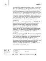
The general architecture of a 3G network is seen in Figure 2.1. In this design, the
Mobile Next Broadband Gateway serves as the gateway GPRS support node (GGSN).
17
`
Figure 2.1: 3G Mobile Network Architecture
A 3G mobile network is made up of three primary components:
A network of radio stations (RAN). Cell towers and base stations are
arranged in a hierarchical order. Base transceiver stations (BTSs) or NobeBs in 3G are
the base stations. There are additionally Radio Network Controllers (RNCs) that
connect to the BTSs to form a Radio Network Subsystem in some versions (RNS).
The UMTS Terrestrial Radio Access Network is made up of RNSs that use the
Wideband CDMA (WCDMA) air interface option (UTRAN). In Figure 2.1, all of
them are referred to as "network devices." The crucial element is that in the 3G
network topology, all cell tower handovers are centralized.
An IP-based core network that connects the RAN to the 3G service
network. All of the switches, routers, and other network components necessary to
carry mobile traffic make up the core network.
A service network that is connected to the main network. Accounting
information (current balance), short message service (SMS) messaging, paging, and
voice mail are some of the services reachable (the servers in Figure 2.1) that are
unique to the service provider. Other services, such as the Internet, other Internet
service providers (ISPs), and business network virtual private networks, are accessible
via the GGSN (which is not officially part of the 3G service network) (VPNs). A
GGSN may be setup on the Mobile Next Broadband Gateway.
The RAN, core network, and service network (as well as the GGSN) make
up the public land mobile network in 3G. (PLMN). A PLMN (or "land" network)
differs from a maritime network.
18
`
2.3. Circuit switching (CS), Packaging Switching (PS), Channel Switching
Services and Packaging Switching Service
3G provides circuit-switched telephony and video services as well as packetswitched internet access.
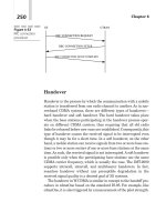
CS (circuit switch): Circuit switching is a telecommunications network
implementation technique in which two network nodes create a dedicated
communications channel (circuit) via the network before communicating. The circuit
guarantees the channel's full bandwidth and remains connected during the
communication session. The circuit works as though the nodes were physically linked
in the same way as an electrical circuit does. Circuit switching began in analog
telephone networks, when the network established a dedicated circuit between two
telephones for the duration of a call. It differs from message switching and packet
switching, which employ trunklines between switching centers to transport data
between several nodes in the form of data packets without the requirement of
dedicated circuits.
Figure 2.2: Circuit switching (CS)
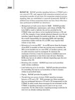
Packet Switching (PS): is the process of a networking or telecommunications
equipment accepting a packet and routing it to a telecommunications device that will
get it closer to its target. Data is delivered across the telecommunications network in
brief bursts or "packets" that carry sequence numbers so that they may be reassembled
at the destination via packet switching. Switches are wide-area network (WAN)
devices that route packets from one end of a packet-switched network to the other.
Depending on variables like traffic congestion and switch availability, data within the
same communication session may be sent across numerous alternative channels.
19
`
Figure 2.3: Packet Switching (PS)
Circuit Switched Services (CS Service): This is a service in which each terminal
is assigned a distinct channel and has complete rights to utilize the channel's resources
throughout the call, but must pay for the entire duration regardless of whether it
transmits. Circuit-switched (CS) and packet-switched (PS) services are also available
(PS). Typically, this service is utilized for real-time (voice) services.
Packet-switched service (PS Service): is a service in which numerous terminals
share a channel and each terminal only uses the channel's resources when data has to
be exchanged, and each terminal only pays for the amount of data received. Only
packet-switched networks support packet-switched services (PS). This service is best
suited for non-real-time services (data transmission), but because to developments in
service technology, it can also be utilized for real-time services (VoIP). Packet
switching can be done on an ATM or IP basis.
Asynchronous Transfer Mode (ATM) is a transmission and switching method
that separates the data to be sent into 53 bytes cells. 5 header bytes (carrying routing
information) and 48 payload bytes make up an ATM cell (containing user data). Fast
switching is possible with ATM switches because they use conventional hardware
switching based on header routing information rather than error detection in each cell.
Virtual path (VP) and virtual channel (VC) are two types of routing information
included in the header (VC). Connection control via VC (the user's channel) and VP
(a group of VCs) allows for scalable and highly flexible operation and administration.
VP is frequently constructed utilizing system data at the time of network
establishment. ATM in the core network provides several advantages, including the
ability to control traffic in conjunction with the RAN, the ability to implement CS and
PS functions in the same architecture, and the ability to implement CS and PS
functions in the same architecture.
20
`
Router IP (Internet Protocol) is a method of separating data into payload
packets during transmission. Following that, each packet receives a header with the
switch's addressing information. In mobile communications, an additional header is
required to route according to the mobile's current location since the position of the
mobile terminal varies. This type of route is referred to as tunneling. GTP and MIP
(Mobile IP: mobile IP) are two ways that may be utilized to do this (GPRS Tunnel
Protocol: GPRS tunneling protocol). A tunnel is a transmission channel in which an IP
packet is wrapped within a header at its input with the recipient's address (in this case,
the mobile's current address) and unencapsulated at its output with instructions on
how to remove the header wrapper.
Standards have been built on 3G WCDMA UMTS from its introduction in 1999,
when ATM was the primary packet-switched technology. Packet switches, on the
other hand, will be IP switches or routers since telecommunications networks are
being built on the internet today and in the future.
2.4. Traffic Types and Services Supported 3G WCDMA UMTS
As 3G mobile communication enables faster transmission, Internet access and
other storage of quantitative information data will develop faster. In addition, 3G
mobile communication is also used for service languages. In general, 3G mobile
phone centers support multimedia communication services. Therefore, each traffic
type should guarantee a QoS level of security according to the service's application.
QoS at W-CDMA is classified as follows:
There are four different QoS classes:
Conversational class: Information interaction requires a small delay (unrestricted
rows).
Streaming class: One-way information of the stream query service with delay
(terminal real-time delivery stream: Video Streaming)
Interactive class: Requires reply in a certain time and low error rate (Web
browsing, server access limited).
Background class: Requires best-effort services to be performed in the
background (e-mail, file download: Video Download)
21
`
The 3WCDMA UMTS operating environment is divided into four regions with
the following Rb serving bit rates:
• Zone 1: indoor, pico cell, Rb 2Mbps
• Region 2: city, cell, Rb 384 kbps
• Region 2: suburbs, macro plots, Rb 144 kbps
• Region 4: Global, Rb = 12.2 kbps
Table 2.1. Classification of services at 3GWDCMA UMTS
Type
Classification
Detailed service
Mobile
Mobile service
Mobile terminal/personal mobility/service
service
mobility
Location
Mobile tracking/smart mobile tracking
information
service
Audio Service
- High quality audio service (16-64 kbps)
- AM radio service (32-64 kbps)
- FM radio service (64-384 kbps)
Telecomm
Data Service
- Average speed metric service (64-144 kbps)
unication
- Relatively high-speed data service (144 kbps-
services
2Mbps)
- High-speed data service ( 2Mbps)
Multimedia
- Video Services (384 kbps)
service
- Motion picture service (384kbps- 2 Mbps)
- Real-time motion picture service ( 2 Mbps)
Simple Internet
Web Access Service (384 kbps-2Mbps)
Service
Internet
service
Real-time Internet
Internet Service (384 kbps-2Mbps)
Service
Multimedia
Real-time Multimedia Website Service
22
`
Type
Classification
Detailed service
internet service
( 2Mbps)
R3, R4, and R5 are the three key releases that make up 3G WCDMA UMTS. The
fundamental networks R3 and R4 are divided into two domains: the CS domain
(Circuit Switch: circuit switching) and the PS domain (Passive Switching) (Packet
Switch: packet switching). This combination is appropriate for the early stages of the
PS's development, when the PS has yet to respond properly to real-time services like
voice and video. The speech services will be handled by the CS domain at this time,
while data will be transferred by the PS domain. R4 is superior to R3 in that the CS
domain is soft-switched, allowing the whole transport network between the switches
to be run via IP. The three 3G WCDMA UMTS designs described above are discussed
further below.
2.5. Architecture 3G WCDMA UMTS R3
Both circuit switched and packet switched connections are supported by
WCDMA UMTS R3: up to 384 Mbps in the CS domain and 2Mbps in the PS domain.
These high-speed connections allow mobile users to access a new range of services
similar to those available on fixed-line telephone networks and the Internet. Video
telephony (video conferencing), high-quality audio (CD), and high transmission
speeds at the terminal are among these services. Another benefit of GPRS is the
ability to stay "always connected" to the Internet. UMTS also offers improved
location information, allowing location-based services to function more effectively.
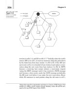
A UMTS network consists of three parts: the mobile equipment (UE: User
Equipment), the UMTS terrestrial radio access network (UTRAN: UMTS Terrestrial
Radio Network), and the core network (CN: Core Network). The UE consists of three
devices: a terminal (TE), a mobile device (ME) and a UMTS subscriber identity
module (USIM: UMTS Subscriber Identity Module). UTRAN consists of radio
network systems (RNS: Radio Network System) and each RNS includes RNC (Radio
Network Controller: radio network controller) and the B nodes connected to it. The
CN core network includes circuit switched, packet switched and HE (Home
Environment) domains. HE includes the following databases: AuC (Authentication
Center), HLR (Home Location Register) and EIR (Equipment Identity Register).
23
`
Figure 2.4: 3G Architecture WCDMA UMTS R3
2.5.1. User Equipment (UE)
UE (User Equipment) is the user's UMTS network terminal. It can be said that
this is the part of the system with the most devices, and its development will greatly
affect the applications and services available. Rapidly falling prices will facilitate the
purchase of UMTS equipment by users. This is achieved by standardizing the radio
interface and installing all the intelligence on the smart cards.
2.5.1.1. Terminals (TEs)
Since the terminal was now not merely for telephony but also providing new
metric services, its name was changed to terminal. Many terminals based on the new
principles have been developed by the major manufacturers, but only a handful have
made it into production. Although the terminals are expected to vary in size and
design, they all have large screens and fewer keys than 2G. The main reason is to
increase the use of the terminal for more data services and so the terminal becomes a
combination of mobile phones, modems, and calculators.
The terminal supports two interfaces. The Uu interface defines the radio link
(WCDMA interface). It takes care of the entire physical connection to the UMTS
network. The second interface is the Cu interface between the UMTS IC card (UICC)
and the terminal. This interface follows the standard for smart cards.
Although terminal manufacturers have a lot of device ideas, they must follow a
minimum set of standard definitions so that users with different terminals can access a
number of functions. baseline in the same way.
These standards include:
Keyboard (physical keys or virtual keys on the screen)
24
`
Register a new password
Change PIN
PIN/PIN2 unblocking (PUK)
Display IMEI
Call control
The rest of the interface will be reserved for designers and users will choose their
terminal based on two standards (if the 2G trend continues) is design and interface.
The interface is a combination of the size and information provided by the screen
(touch button screen), keys, and menus.
2.5.1.2. UICC
UMTS IC card is a smart card. What we care about it is the amount of memory
and processor speed it provides. The USIM application runs on top of the UICC.
2.5.1.3. USIM
In the GSM system, the SIM card stores personal information (subscriber
registration) hard-installed on the card. This has changed in UMTS, the UMTS
Subscriber Identity Module is installed as an application on the UICC. This allows for
more applications and more digital signatures (keys) to be stored along with the
USIM for other purposes (secure banking access codes). It is also possible to have
multiple USIMs on the same UICC to support access to multiple networks.
The USIM contains the functions and metrics needed to identify and authenticate
a subscriber in the UMTS network. It can even save a copy of the subscriber's profile.
The user must authenticate himself to the USIM by entering the PIN code. This
ensures that only authorized users can access the UMTS network. The network will
only provide services to end users based on the registered USIM identity.
2.5.2. UMTS Radio Access Network
UTRAN (UMTS Terrestrial Radio Access Network: UMTS Terrestrial Radio
Access Network) is the link between the user and the CN. It consists of elements that
secure UMTS communications over the air and control them.
UTRAN is defined between two interfaces. The Iu interface between UTRAN and
CN, consists of two parts: IuPS for the packet-switched domain and IuCS for the
circuit-switched domain; Uu interface between UTRAN and the user device. Between
these two interfaces are two nodes, RNC and node B.
25