Tài liệu ARM Architecture Reference Manual- P10 ppt
Bạn đang xem bản rút gọn của tài liệu. Xem và tải ngay bản đầy đủ của tài liệu tại đây (380.38 KB, 30 trang )
ARM Addressing Modes
ARM DDI 0100E
Copyright © 1996-2000 ARM Limited. All rights reserved.
A5-55
Table 5-1 shows the relationship for LDM instructions.
Table 5-2 shows the relationship for STM instructions.
Table 5-1 LDM addressing modes
Non-stack addressing mode Stack addressing mode L bit P bit U bit
LDMDA (Decrement After) LDMFA (Full Ascending) 1 0 0
LDMIA (Increment After) LDMFD (Full Descending) 1 0 1
LDMDB (Decrement Before) LDMEA (Empty Ascending) 1 1 0
LDMIB (Increment Before) LDMED (Empty Descending) 1 1 1
Table 5-2 STM addressing modes
Non-stack addressing mode Stack addressing mode L bit P bit U bit
STMDA (Decrement After) STMED (Empty Descending) 0 0 0
STMIA (Increment After) STMEA (Empty Ascending) 0 0 1
STMDB (Decrement Before) STMFD (Full Descending) 0 1 0
STMIB (Increment Before) STMFA (Full Ascending) 0 1 1
Please purchase PDF Split-Merge on www.verypdf.com to remove this watermark.
ARM Addressing Modes
A5-56
Copyright © 1996-2000 ARM Limited. All rights reserved.
ARM DDI 0100E
5.5 Addressing Mode 5 - Load and Store Coprocessor
There are four addressing modes which are used to calculate the address of a Load or Store Coprocessor
instruction. The general instruction syntax is:
<opcode>{<cond>}{L} <coproc>,<CRd>,<addressing_mode>
where <addressing_mode> is one of the following four options:
1. [<Rn>,#+/-<offset_8>*4]
See Load and Store Coprocessor - Immediate offset on page A5-58.
2. [<Rn>,#+/-<offset_8>*4]!
See Load and Store Coprocessor - Immediate pre-indexed on page A5-60.
3. [<Rn>],#+/-<offset_8>*4
See Load and Store Coprocessor - Immediate post-indexed on page A5-62.
4. [<Rn>],<option>
See Load and Store Coprocessor - Unindexed on page A5-64.
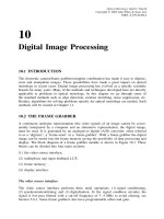
5.5.1 Encoding
The following diagram shows the encoding for this addressing mode:
The P bit Has two meanings:
P == 1 Indicates the use of post-indexed addressing or unindexed addressing (the W bit
determines which). The base register value is used for the memory address.
P == 0 Indicates the use of offset addressing or pre-indexed addressing (the W bit
determines which). The memory address is generated by applying the offset to
the base register value.
The U bit Has two meanings:
U == 1 Indicates that the offset is added to the base.
U == 0 Indicates that he offset is subtracted from the base
The N bit The meaning of this bit is coprocessor-dependent. Its recommended use is to distinguish
between different-sized values to be transferred.
The W bit Has two meanings:
W == 1 Indicates that the memory address is written back to the base register.
W == 0 Indicates that the base register value is unchanged.
31 28 27 26 25 24 23 22 21 20 19 16 15 12 11 8 7 0
cond 1 1 0 P U N W L Rn CRd cp# offset_8
Please purchase PDF Split-Merge on www.verypdf.com to remove this watermark.
ARM Addressing Modes
ARM DDI 0100E
Copyright © 1996-2000 ARM Limited. All rights reserved.
A5-57
Also:
• If P == 0, this distinguishes unindexed addressing (W == 0) from post-indexed
addressing (W == 1). For unindexed addressing, U must equal 1 or the result is either
UNDEFINED or UNPREDICTABLE (see Coprocessor instruction extension space on
page A3-33).
• If P == 1, this distinguishes offset addressing (W == 0) from pre-indexed addressing
(W == 1).
The L bit Distinguishes between Load (L == 1) and Store (L == 0) instructions.
Please purchase PDF Split-Merge on www.verypdf.com to remove this watermark.
ARM Addressing Modes
A5-58
Copyright © 1996-2000 ARM Limited. All rights reserved.
ARM DDI 0100E
5.5.2 Load and Store Coprocessor - Immediate offset
This addressing mode produces a sequence of consecutive addresses. The first address is calculated by
adding or subtracting four times the value of an immediate offset to or from the value of the base register
Rn. The subsequent addresses in the sequence are produced by incrementing the previous address by four
until the coprocessor signals the end of the instruction. This allows a coprocessor to access data whose size
is coprocessor-defined.
The coprocessor must not request a transfer of more than 16 words.
Syntax
[<Rn>, #+/-<offset_8>*4]
where:
<Rn> Specifies the register containing the base address.
<offset_8> Specifies the immediate offset that is multiplied by 4, then added to or subtracted
from the value of Rn to form the address.
Architecture version
Version 2 and above
Operation
if ConditionPassed(cond) then
if U == 1 then
address = Rn + offset_8 * 4
else /* U == 0 */
address = Rn - offset_8 * 4
start_address = address
while (NotFinished(coprocessor[cp_num]))
address = address + 4
end_address = address
31 28 27 26 25 24 23 22 21 20 19 16 15 12 11 8 7 0
cond 1101UN0L Rn CRd cp_num offset_8
Please purchase PDF Split-Merge on www.verypdf.com to remove this watermark.
ARM Addressing Modes
ARM DDI 0100E
Copyright © 1996-2000 ARM Limited. All rights reserved.
A5-59
Notes
The N bit Is coprocessor-dependent.
The L bit Distinguishes between Load (L==1) and Store (L==0) instructions.
Use of R15 If R15 is specified as register Rn, the value used is the address of the instruction plus 8.
Please purchase PDF Split-Merge on www.verypdf.com to remove this watermark.
ARM Addressing Modes
A5-60
Copyright © 1996-2000 ARM Limited. All rights reserved.
ARM DDI 0100E
5.5.3 Load and Store Coprocessor - Immediate pre-indexed
This addressing mode produces a sequence of consecutive addresses. The first address is calculated by
adding or subtracting four times the value of an immediate offset to or from the value of the base register
Rn. If the condition specified in the instruction matches the condition code status, the first address is written
back to the base register Rn. The subsequent addresses in the sequence are produced by incrementing the
previous address by four until the coprocessor signals the end of the instruction. This allows a coprocessor
to access data whose size is coprocessor-defined.
The coprocessor must not request a transfer of more than 16 words.
Syntax
[<Rn>, #+/-<offset_8>*4]!
where:
<Rn> Specifies the register containing the base address.
<offset_8> Specifies the immediate offset that is multiplied by 4, then added to or subtracted
from the value of Rn to form the address.
! Sets the W bit, causing base register update.
Architecture version
Version 2 and above
Operation
if ConditionPassed(cond) then
if U == 1 then
Rn = Rn + offset_8 * 4
else /* U == 0 */
Rn = Rn - offset_8 * 4
start_address = Rn
address = start_address
while (NotFinished(coprocessor[cp_num]))
address = address + 4
end_address = address
31 28 27 26 25 24 23 22 21 20 19 16 15 12 11 8 7 0
cond 1101UN1L Rn CRd cp_num offset_8
Please purchase PDF Split-Merge on www.verypdf.com to remove this watermark.
ARM Addressing Modes
ARM DDI 0100E
Copyright © 1996-2000 ARM Limited. All rights reserved.
A5-61
Notes
The N bit Is coprocessor-dependent.
The L bit Distinguishes between Load (L==1) and Store (L==0) instructions.
Use of R15 Specifying R15 as register Rn has
UNPREDICTABLE results.
Please purchase PDF Split-Merge on www.verypdf.com to remove this watermark.
ARM Addressing Modes
A5-62
Copyright © 1996-2000 ARM Limited. All rights reserved.
ARM DDI 0100E
5.5.4 Load and Store Coprocessor - Immediate post-indexed
This addressing mode produces a sequence of consecutive addresses. The first address is the value of the
base register Rn. The subsequent addresses in the sequence are produced by incrementing the previous
address by four until the coprocessor signals the end of the instruction. This allows a coprocessor to access
data whose size is coprocessor-defined.
If the condition specified in the instruction matches the condition code status, the base register Rn is updated
by adding or subtracting four times the value of an immediate offset to or from the value of the base register
Rn.
The coprocessor must not request a transfer of more than 16 words.
Syntax
[<Rn>], #+/-<offset_8>*4
where:
<Rn> Specifies the register containing the base address.
<offset_8> Specifies the immediate offset that is multiplied by 4, then added to or subtracted
from the value of Rn to form the address.
Architecture version
Version 2 and above
Operation
if ConditionPassed(cond) then
start_address = Rn
if U == 1 then
Rn = Rn + offset_8 * 4
else /* U == 0 */
Rn = Rn - offset_8 * 4
address = start_address
while (NotFinished(coprocessor[cp_num]))
address = address + 4
end_address = address
31 28 27 26 25 24 23 22 21 20 19 16 15 12 11 8 7 0
cond 1100UN1L Rn CRd cp_num offset_8
Please purchase PDF Split-Merge on www.verypdf.com to remove this watermark.
ARM Addressing Modes
ARM DDI 0100E
Copyright © 1996-2000 ARM Limited. All rights reserved.
A5-63
Notes
The N bit Is coprocessor-dependent.
The L bit Distinguishes between Load (L==1) and Store (L==0) instructions.
Use of R15 Specifying R15 as register Rn has
UNPREDICTABLE results.
Please purchase PDF Split-Merge on www.verypdf.com to remove this watermark.
ARM Addressing Modes
A5-64
Copyright © 1996-2000 ARM Limited. All rights reserved.
ARM DDI 0100E
5.5.5 Load and Store Coprocessor - Unindexed
This addressing mode produces a sequence of consecutive addresses. The first address is the value of the
base register Rn. The subsequent addresses in the sequence are produced by incrementing the previous
address by four until the coprocessor signals the end of the instruction. This allows a coprocessor to access
data whose size is coprocessor-defined.
The base register Rn is not updated. Bits[7:0] of the instruction are therefore not used by the ARM, either
for the address calculation or to calculate a new value for the base register, and so can be used to specify
additional instruction options to the coprocessor.
The coprocessor must not request a transfer of more than 16 words.
Syntax
[<Rn>], <option>
where:
<Rn> Specifies the register containing the base address.
<option> Specifies additional instruction options to the coprocessor. The <option> is specified in
the instruction syntax as an integer in the range 0-255, surrounded by { and }.
Architecture version
Version 2 and above
Operation
if ConditionPassed(cond) then
start_address = Rn
address = start_address
while (NotFinished(coprocessor[cp_num]))
address = address + 4
end_address = address
31 28 27 26 25 24 23 22 21 20 19 16 15 12 11 8 7 0
cond 1100UN0L Rn CRd cp_num option
Please purchase PDF Split-Merge on www.verypdf.com to remove this watermark.
ARM Addressing Modes
ARM DDI 0100E
Copyright © 1996-2000 ARM Limited. All rights reserved.
A5-65
Notes
The N bit Is coprocessor-dependent.
The L bit Distinguishes between Load (L==1) and Store (L==0) instructions.
Use of R15 If R15 is specified as register Rn, the value used is the address of the instruction plus 8.
The U bit If bit[23] (the Up/down bit) is not set, the result is either
UNDEFINED or UNPREDICTABLE (see
Coprocessor instruction extension space on page A3-33).
Option bits Are unused by the ARM in this addressing mode, and therefore can be used to request
additional instruction options in a coprocessor-dependent fashion.
Please purchase PDF Split-Merge on www.verypdf.com to remove this watermark.
ARM Addressing Modes
A5-66
Copyright © 1996-2000 ARM Limited. All rights reserved.
ARM DDI 0100E
Please purchase PDF Split-Merge on www.verypdf.com to remove this watermark.
ARM DDI 0100E
Copyright © 1996-2000 ARM Limited. All rights reserved.
A6-1
Chapter A6
The Thumb Instruction Set
This chapter introduces the Thumb instruction set and describes how Thumb uses the ARM programmer’s
model. It contains the following sections:
• About the Thumb instruction set on page A6-2
• Instruction set encoding on page A6-4
• Branch instructions on page A6-6
• Data-processing instructions on page A6-8
• Load and Store Register instructions on page A6-15
• Load and Store Multiple instructions on page A6-18
• Exception-generating instructions on page A6-20
• Undefined instruction space on page A6-21.
Please purchase PDF Split-Merge on www.verypdf.com to remove this watermark.
The Thumb Instruction Set
A6-2
Copyright © 1996-2000 ARM Limited. All rights reserved.
ARM DDI 0100E
6.1 About the Thumb instruction set
The Thumb instruction set is a re-encoded subset of the ARM instruction set. Thumb is designed to increase
the performance of ARM implementations that use a 16-bit or narrower memory data bus and to allow better
code density than ARM. T variants of the ARM architecture incorporate both a full 32-bit ARM instruction
set and the 16-bit Thumb instruction set. Every Thumb instruction is encoded in 16 bits.
Thumb does not alter the underlying programmer’s model of the ARM architecture. It merely presents
restricted access to it. All Thumb data-processing instructions operate on full 32-bit values, and full 32-bit
addresses are produced by both data-access instructions and instruction fetches.
When the processor is executing Thumb instructions, eight general-purpose integer registers are available,
R0 to R7, which are the same physical registers as R0 to R7 when executing ARM instructions. Some
Thumb instructions also access the Program Counter (ARM Register 15), the Link Register
(ARM Register 14) and the Stack Pointer (ARM Register 13). Further instructions allow limited access to
ARM registers 8 to 15, which are know as the high registers.
When R15 is read, bit[0] is zero and bits[31:1] contain the PC. When R15 is written, bit[0] is
IGNORED and
bits[31:1] are written to the PC. Depending on how it is used, the value of the PC is either the address of the
instruction plus 4 or is
UNPREDICTABLE.
Thumb does not provide direct access to the CPSR or any SPSR (as the MSR and MRS instructions do in
the ARM instruction set)). Thumb execution is flagged by the T bit (bit[5]) in the CPSR:
T == 0 32-bit instructions are fetched (and the PC is incremented by four) and are executed as ARM
instructions.
T == 1 16-bit instructions are fetched (and the PC is incremented by two) and are executed as
Thumb instructions.
Note
The Thumb instruction set is only compatible with the 32-bit ARM architectures. Thumb is not
recommended for use with 26-bit architectures or with 26-bit compatibility options on 32-bit architectures.
6.1.1 Entering Thumb state
Thumb execution is normally entered by executing an ARM BX instruction (Branch and Exchange). This
instruction branches to the address held in a general-purpose register, and if bit[0] of that register is 1,
Thumb execution begins at the branch target address. If bit[0] of the target register is 0, ARM execution
continues from the branch target address. On architecture versions 5 and above, BLX instructions and
LDR/LDM instructions that load the PC can be used similarly.
Thumb execution can also be initiated by setting the T bit in the SPSR and executing an ARM instruction
which restores the CPSR from the SPSR (a data-processing instruction with the S bit set and the PC as the
destination, or a Load Multiple with Restore CPSR instruction). This allows an operating system to
automatically restart a process independent of whether that process is executing Thumb code or ARM code.
The result is
UNPREDICTABLE if the T bit is altered directly by writing the CPSR.
Please purchase PDF Split-Merge on www.verypdf.com to remove this watermark.
The Thumb Instruction Set
ARM DDI 0100E
Copyright © 1996-2000 ARM Limited. All rights reserved.
A6-3
6.1.2 Exceptions
Exceptions generated during Thumb execution switch to ARM execution before executing the exception
handler (whose first instruction is at the hardware vector). The state of the T bit is preserved in the SPSR,
and the LR of the exception mode is set so that the normal return instruction performs correctly, regardless
of whether the exception occurred during ARM or Thumb execution. Table 6-1 lists the values of the
exception mode LR for exceptions generated during Thumb execution.
Note
For each exception, the return instruction indicated by Table 6-1 is the same as the return instruction
required if the exception occurred during ARM execution, for the primary or only method of return from
that instruction listed in Exceptions on page A2-13. However, the following two types of exception have a
secondary return method, for which different return instructions are needed depending on whether the
exception occurred during ARM or Thumb execution:
• For the Data Abort exception, the primary method of return causes execution to resume at the aborted
instruction, which causes it to be re-executed. As described in Data Abort (data access memory
abort) on page A2-17, it is also possible to return to the next instruction after the aborted instruction,
using a SUBS PC,R14,#4 instruction. If this type of return is required for a data abort caused by
a Thumb instruction, use SUBS PC,R14,#6 for the return instruction.
• For the Undefined Instruction exception, the primary method of return causes execution to resume at
the next instruction after the undefined instruction. As described in Undefined Instruction exception
on page A2-15, it is also possible to return to the undefined instruction itself, using the instruction
SUBS PC,R14,#4. If this type of return is required for a Thumb undefined instruction, use SUBS
PC,R14,#2 for the return instruction. However, the main use of this type of return is for some types
of coprocessor instruction, and as the Thumb instruction set does not contain any coprocessor
instructions, you are unlikely to need this secondary method of return for Thumb instructions.
When these secondary methods of return are used, the exception handler code must test the SPSR T bit in
order to determine which of the two return instructions to use.
Table 6-1 Exception return instructions
Exception Exception link register value Return instruction
Reset
UNPREDICTABLE value -
Undefined Address of undefined instruction + 2 MOVS PC, R14
SWI Address of SWI instruction + 2 MOVS PC, R14
Prefetch Abort Address of aborted instruction fetch + 4 SUBS PC, R14, #4
Data Abort Address of the instruction that generated the abort + 8 SUBS PC, R14, #8
IRQ Address of the next instruction to be executed + 4 SUBS PC, R14, #4
FIQ Address of the next instruction to be executed + 4 SUBS PC, R14, #4
Please purchase PDF Split-Merge on www.verypdf.com to remove this watermark.
The Thumb Instruction Set
A6-4
Copyright © 1996-2000 ARM Limited. All rights reserved.
ARM DDI 0100E
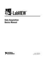
6.2 Instruction set encoding
Figure 6-1 shows the Thumb instruction set encoding. An entry in square brackets, for example [1],
indicates a note on the following page.
Figure 6-1 Thumb instruction set overview
opcode Rd / Rn
Rd / RnRm / Rs
opcode [1] Rd / Rn
PC-relative offset
Shift by immediate
Add/subtract register
Add/subtract immediate
Add/subtract/compare/move immediate
Data-processing register
Special data processing
Load from literal pool
Load/store word/byte immediate offset
Load/store halfword immediate offset
Load/store to/from stack
Add to SP or PC
Load/store register offset
offset
offset
SP-relative offset
15 14 13 12 11 10 9 8 7 6 5 4 3 2 1 0
opcode [1] immediate Rm Rd000
000
000
001
010
010
010
011
100
110
111
000
opc Rm Rn Rd
opc Rn Rdimmediate
immediate
opcode
RmH1 H2
0Rd
1RmRnRd
B L Rn Rd
0 L Rn Rd
1001 L Rd
1 0 1 0 SP Rd immediate
010001
01000111LH2 Rm SBZ
Branch/exchange
instruction set [3]
1
opcode
Miscellaneous:
See Figure 6-2
1011 xxxxx xx xxxxx
Load/store multiple
Conditional branch
Undefined instruction
Software interrupt
Unconditional branch
Undefined instruction
BL/BLX prefix
BL suffix
110
111
111
1 cond [2] offset
xxxxxxxx1101101 1
1111 1 0 1 1 immediate
0 0 offset
xx1xx xx xxxx1110 1
offset10
1 1 1 offset11
1 1 0 0 L Rn register list
BLX suffix [4] 1 1 1 0 1 offset 0
Please purchase PDF Split-Merge on www.verypdf.com to remove this watermark.
The Thumb Instruction Set
ARM DDI 0100E
Copyright © 1996-2000 ARM Limited. All rights reserved.
A6-5
1. The opc field is not allowed to be 11 in this line. Other lines deal with the case that the opc field is
11.
2. The cond field is not allowed to be 1110 or 1111 in this line. Other lines deal with the cases where
the cond field is 1110 or 1111.
3. The form with L==1 is
UNPREDICTABLE prior to ARM architecture version 5.
4. This is an undefined instruction prior to ARM architecture version 5.
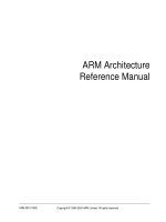
6.2.1 Miscellaneous instructions
Figure 6-2 lists miscellaneous Thumb instructions. An entry in square brackets, for example [1], indicates
a note below the figure.
Figure 6-2 Miscellaneous Thumb instructions
1. This is an undefined instruction prior to ARM architecture version 5.
Note
Any instruction with bits[15:12] = 1011, and which is not shown in Figure 6-2, is an undefined instruction.
15 14 13 12 11 10 9 8 7 6 5 4 3 2 1 0
Adjust stack pointer
Push/pop register list
0001 0 1 1 0 opc immediate
1 0 1 1 L R register list10
1 0 1 1 1 0 immediate11Software breakpoint [1]
Please purchase PDF Split-Merge on www.verypdf.com to remove this watermark.
The Thumb Instruction Set
A6-6
Copyright © 1996-2000 ARM Limited. All rights reserved.
ARM DDI 0100E
6.3 Branch instructions
Thumb supports six types of branch instruction:
• an unconditional branch that allows a forward or backward branch of up to 2KB
• a conditional branch to allow forward and backward branches of up to 256 bytes
• a Branch with Link (subroutine call) is supported with a pair of instructions that allow forward and
backward branches of up to 4MB
• a Branch and Exchange instruction branches to an address in a register and optionally switches to
ARM code execution
• a Branch with Link and Exchange instruction performs a subroutine call to an address in a register
and optionally switches to ARM code execution
• a second form of Branch with Link and Exchange uses a pair of instructions, similar to Branch with
Link, but additionally switches to ARM code execution.
The encoding for these instructions is given below.
6.3.1 Conditional branch
B<cond> <target_address>
6.3.2 Unconditional branch
B <target_address>
BL <target_address> ; Produces two 16-bit instructions
BLX <target_address> ; Produces two 16-bit instructions
6.3.3 Branch with exchange
BX <Rm>
BLX <Rm>
15 14 13 12 11 8 7 0
1 1 0 1 cond 8_bit_signed_offset
15 14 13 12 11 10 0
1 1 1 H offset_11
15141312111098765 32 0
01000111LH2 Rm SBZ
Please purchase PDF Split-Merge on www.verypdf.com to remove this watermark.
The Thumb Instruction Set
ARM DDI 0100E
Copyright © 1996-2000 ARM Limited. All rights reserved.
A6-7
6.3.4 Examples
B label ; unconditionally branch to label
BCC label ; branch to label if carry flag is clear
BEQ label ; branch to label if zero flag is set
BL func ; subroutine call to function
func
; Include body of function here
MOV PC, LR ; R15=R14, return to instruction after the BL
BX R12 ; branch to address in R12; begin ARM execution if
; bit 0 of R12 is zero; otherwise continue executing
; Thumb code
6.3.5 List of branch instructions
The following instructions follow the formats shown above.
B Conditional Branch. See B (1) on page A7-18.
B Unconditional Branch. See B (2) on page A7-20.
BL Branch with Link. See BL, BLX(1) on page A7-26.
BX Branch and Exchange instruction set. See BX on page A7-32.
BLX Branch with Link and Exchange instruction set. See BL, BLX(1) on page A7-26 and BLX(2)
on page A7-30.
Please purchase PDF Split-Merge on www.verypdf.com to remove this watermark.
The Thumb Instruction Set
A6-8
Copyright © 1996-2000 ARM Limited. All rights reserved.
ARM DDI 0100E
6.4 Data-processing instructions
Thumb data-processing instructions are a subset of the ARM data-processing instructions, as shown in
Table 6-2. All Thumb data-processing instructions in this table set the condition codes.
Table 6-2 Thumb data-processing instructions
Mnemonic Operation Action
ADC Rd, Rm
Add with Carry Rd := Rd + Rm + Carry flag
ADD Rd, Rn, Rm
Add Rd := Rn + Rm
ADD Rd, Rn, #0 to 7
Add Rd := Rn + 3-bit immediate
ADD Rd, #0 to 255
Add Rd := Rd + 8-bit immediate
AND Rd, Rm
Logical AND Rd := Rd AND Rm
ASR Rd, Rm, #1 to 32
Arithmetic Shift Right Rd := Rm ASR 5-bit immediate
ASR Rd, Rs
Arithmetic Shift Right Rd := Rd ASR Rs
BIC Rd, Rm
Bit Clear Rd := Rd AND NOT Rm
CMN Rn, Rm
Compare Negated Update flags after Rn + Rm
CMP Rn, #0 to 255
Compare Update flags after Rn - 8-bit immediate
CMP Rn, Rm
Compare Update flags after Rn - Rm
EOR Rd, Rm
Logical Exclusive OR Rd := Rd EOR Rm
LSL Rd, Rm, #0 to 31
Logical Shift Left Rd := Rm LSL 5-bit immediate
LSL Rd, Rs
Logical Shift Left Rd := Rd LSL Rs
LSR Rd, Rm, #1 to 32
Logical Shift Right Rd := Rm LSR 5-bit immediate
LSR Rd, Rs
Logical Shift Right Rd := Rd LSR Rs
MOV Rd, #0 to 255
Move Rd := 8-bit immediate
MOV Rd, Rn
Move Rd := Rn
MUL Rd, Rm
Multiply Rd := Rm x Rd
MVN Rd, Rm
Move Not Rd := NOT Rm
NEG Rd, Rm
Negate Rd := 0 - Rm
ORR Rd, Rm
Logical (inclusive) OR Rd := Rd OR Rm
Please purchase PDF Split-Merge on www.verypdf.com to remove this watermark.
The Thumb Instruction Set
ARM DDI 0100E
Copyright © 1996-2000 ARM Limited. All rights reserved.
A6-9
For example:
ADD R0, R4, R7 ; R0 = R4 + R7
SUB R6, R1, R2 ; R6 = R1 - R2
ADD R0, #255 ; R0 = R0 + 255
ADD R1, R4, #4 ; R1 = R4 + 4
NEG R3, R1 ; R3 = 0 - R1
AND R2, R5 ; R2 = R2 AND R5
EOR R1, R6 ; R1 = R1 EOR R6
CMP R2, R3 ; update flags after R2 - R3
CMP R7, #100 ; update flags after R7 - 100
MOV R0, #200 ; R0 = 200
ROR Rd, Rs
Rotate Right Rd := Rd ROR Rs
SBC Rd, Rm
Subtract with Carry Rd := Rd - Rm - NOT(Carry Flag)
SUB Rd, Rn, Rm
Subtract Rd := Rn - Rm
SUB Rd, Rn, #0 to 7
Subtract Rd := Rn - 3-bit immediate
SUB Rd, #0 to 255
Subtract Rd := Rd - 8-bit immediate
TST Rn, Rm
Test Update flags after Rn AND Rm
Table 6-2 Thumb data-processing instructions (Continued)
Mnemonic Operation Action
Please purchase PDF Split-Merge on www.verypdf.com to remove this watermark.
The Thumb Instruction Set
A6-10
Copyright © 1996-2000 ARM Limited. All rights reserved.
ARM DDI 0100E
6.4.1 High registers
There are seven types of data-processing instruction which operate on ARM registers 8 to 14 and the PC as
shown in Table 6-3. Apart from CMP, instructions in this table do not change the condition code flags.
For example:
MOV R0, R12 ; R0 = R12
ADD R10, R1, R2 ; R6 = R1 - R2
MOV PC, LR ; PC = R14
CMP R10, R11 ; update flags after R10 - R11
SUB SP, #12 ; increase stack size by 12 bytes
ADD SP, #16 ; decrease stack size by 16 bytes
ADD R2, SP, #20 ; R2 = SP + 20
ADD R0, PC, #500 ; R0 = PC + 500
Table 6-3 High register data-processing instructions
Mnemonic Operation Action
MOV Rd, Rn
Move Rd := Rn
ADD Rd, Rm
Add Rd := Rd + Rm
CMP Rn, Rm
Compare Update flags after Rn - Rm
ADD SP, #0 to 508
Increment stack pointer R13 = R13 + 4* (7-bit immediate)
SUB SP, #0 to 508
Decrement stack pointer R13 = R13 - 4* (7-bit immediate)
ADD Rd, SP, #0 to 1020
Form Stack address Rd = R13 + 4* (8-bit immediate)
ADD Rd, PC, #0 to 1020
Form PC address Rd = PC + 4* (8-bit immediate)
Please purchase PDF Split-Merge on www.verypdf.com to remove this watermark.
The Thumb Instruction Set
ARM DDI 0100E
Copyright © 1996-2000 ARM Limited. All rights reserved.
A6-11
6.4.2 Formats
Data-processing instructions use the following eight instruction formats:
Format 1
<opcode1> <Rd>, <Rn>, <Rm>
<opcode1> := ADD | SUB
Format 2
<opcode2> <Rd>, <Rn>, #<3_bit_immed>
<opcode2> := ADD | SUB
Format 3
<opcode3> <Rd>|<Rn>, #<8_bit_immed>
<opcode3> := ADD | SUB | MOV | CMP
Format 4
<opcode4> <Rd>, <Rm>, #<shift_imm>
<opcode4> := LSL | LSR | ASR
15 14 13 12 11 10 9 8 6 5 3 2 0
000110op_1 Rm Rn Rd
15 14 13 12 11 10 9 8 6 5 3 2 0
000111op_23_bit_immediate Rn Rd
15 14 13 12 11 10 8 7 0
0 0 1 op_3 Rd|Rn 8_bit_immediate
15 14 13 12 11 10 6 5 3 2 0
0 0 0 op_4 shift_immediate Rm Rd
Please purchase PDF Split-Merge on www.verypdf.com to remove this watermark.
The Thumb Instruction Set
A6-12
Copyright © 1996-2000 ARM Limited. All rights reserved.
ARM DDI 0100E
Format 5
<opcode5> <Rd>|<Rn>, <Rm>|<Rs>
<opcode5> := MVN | CMP | CMN | TST | ADC | SBC | NEG | MUL |
LSL | LSR | ASR | ROR | AND | EOR | ORR | BIC
Format 6
ADD <Rd>, <reg>, #<8_bit_immed>
<reg> := SP | PC
Format 7
<opcode6> SP, SP, #<7_bit_immed>
<opcode6> := ADD | SUB
Format 8
<opcode7> <Rd>|<Rn>, <Rm>
<opcode7> := MOV | ADD | CMP
15 14 13 12 11 10 9 6 5 3 2 0
010000 op_5 Rm|Rs Rd|Rn
15 14 13 12 11 10 8 7 0
1010reg Rd 8_bit_immediate
15 14 13 12 11 10 9 8 7 6 0
10110000op_6 7_bit_immediate
15141312111098765 32 0
010001opcodeH1H2 Rm Rd|Rn
Please purchase PDF Split-Merge on www.verypdf.com to remove this watermark.
The Thumb Instruction Set
ARM DDI 0100E
Copyright © 1996-2000 ARM Limited. All rights reserved.
A6-13
6.4.3 List of data-processing instructions
The following instructions follow the formats shown above.
ADC Add with Carry. See ADC on page A7-4.
ADD Add (immediate). See ADD (1) on page A7-5.
ADD Add (large immediate). See ADD (2) on page A7-6.
ADD Add (register). See ADD (3) on page A7-7.
ADD Add high registers. See ADD (4) on page A7-8.
ADD Add (immediate to program counter). See ADD (5) on page A7-10.
ADD Add (immediate to stack pointer). See ADD (6) on page A7-11.
ADD Increment stack pointer. See ADD (7) on page A7-12.
AND Logical AND. See AND on page A7-13.
ASR Arithmetic Shift Right (immediate). See ASR (1) on page A7-14.
ASR Arithmetic Shift Right (register). See ASR (2) on page A7-16.
BIC Bit Clear. See BIC on page A7-22.
CMN Compare Negative (register). See CMN on page A7-34.
CMP Compare (immediate). See CMP (1) on page A7-35.
CMP Compare (register). See CMP (2) on page A7-36.
CMP Compare high registers. See CMP (3) on page A7-37.
EOR Exclusive OR. See EOR on page A7-39.
LSL Logical Shift Left (immediate). See LSL (1) on page A7-59.
LSL Logical Shift Left (register). See LSL (2) on page A7-60.
LSR Logical Shift Right (immediate). See LSR (1) on page A7-62.
LSR Logical Shift Right (register). See LSR (2) on page A7-64.
MOV Move (immediate). See MOV (1) on page A7-66.
MOV Move a low register to another low register. See MOV (2) on page A7-67.
MOV Move high registers. See MOV (3) on page A7-68.
MUL Multiply. See MUL on page A7-70.
MVN Move NOT (register). See MVN on page A7-72.
NEG Negate (register). See NEG on page A7-73.
Please purchase PDF Split-Merge on www.verypdf.com to remove this watermark.