Tài liệu Sổ tay RFID (P2) ppt
Bạn đang xem bản rút gọn của tài liệu. Xem và tải ngay bản đầy đủ của tài liệu tại đây (535.75 KB, 18 trang )
2
Differentiation Features of
RFID Systems
2.1 Fundamental Differentiation Features
RFID systems exist in countless variants, produced by an almost equally high number
of manufacturers. If we are to maintain an overview of RFID systems we must seek out
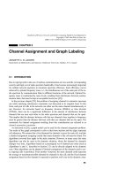
features that can be used to differentiate one RFID system from another (Figure 2.1).
RFID systems operate according to one of two basic procedures: full duplex (FDX)/
half duplex (HDX) systems, and sequential systems (SEQ).
In full and half duplex systems the transponder’s response is broadcast when the
reader’s RF field is switched on. Because the transponder’s signal to the receiver
antenna can be extremely weak in comparison with the signal from the reader itself,
appropriate transmission procedures must be employed to differentiate the transpon-
der’s signal from that of the reader. In practice, data transfer from transponder to
reader takes place using load modulation, load modulation using a subcarrier, but also
(sub)harmonics of the reader’s transmission frequency.
In contrast, sequential procedures employ a system whereby the field from the reader
is switched off briefly at regular intervals. These gaps are recognised by the transponder
and used for sending data from the transponder to the reader. The disadvantage of
the sequential procedure is the loss of power to the transponder during the break in
transmission, which must be smoothed out by the provision of sufficient auxiliary
capacitors or batteries.
The data capacities of RFID transponders normally range from a few bytes to several
kilobytes. So-called 1-bit transponders represent the exception to this rule. A data
quantity of exactly 1-bit is just enough to signal two states to the reader: ‘transponder
in the field’ or ‘no transponder in the field’. However, this is perfectly adequate to
fulfil simple monitoring or signalling functions. Because a 1-bit transponder does not
need an electronic chip, these transponders can be manufactured for a fraction of a
penny. For this reason, vast numbers of 1-bit transponders are used in Electronic Article
Surveillance (EAS) to protect goods in shops and businesses. If someone attempts to
leave the shop with goods that have not been paid for the reader installed in the exit
recognises the state ‘transponder in the field’ and initiates the appropriate reaction. The
1-bit transponder is removed or deactivated at the till when the goods are paid for.
RFID Handbook: Fundamentals and Applications in Contactless Smart Cards and Identification,
Second Edition
Klaus Finkenzeller
Copyright
2003 John Wiley & Sons, Ltd.
ISBN: 0-470-84402-7
12 2 DIFFERENTIATION FEATURES OF RFID SYSTEMS
FDX SEQ
Back-scatter/load
modulation
Operation type:
Data quantity:
Power supply:
Programmable:
Data carrier’s
operating principle:
Frequency range:
Response frequency:
>1 Bit 1 Bit EAS
Yes No
IC
LF RF
Battery Passive
1/
n
-fold
SAW
State
machine
mP
Microwave
Sub
harmonics
Other
1:1 Various
Physical
Yes/No
Sequence:
Data transfer
transponder → reader
Figure 2.1 The various features of RFID systems (Integrated Silicon Design, 1996)
The possibility of writing data to the transponder provides us with another way of
classifying RFID systems. In very simple systems the transponder’s data record, usually
a simple (serial) number, is incorporated when the chip is manufactured and cannot be
altered thereafter. In writable transponders, on the other hand, the reader can write data
to the transponder. Three main procedures are used to store the data: in inductively
coupled RFID systems EEPROMs (electrically erasable programmable read-only mem-
ory) are dominant. However, these have the disadvantages of high power consumption
during the writing operation and a limited number of write cycles (typically of the
order of 100 000 to 1 000 000). FRAMs (ferromagnetic random access memory) have
recently been used in isolated cases. The read power consumption of FRAMs is lower
than that of EEPROMs by a factor of 100 and the writing time is 1000 times lower.
Manufacturing problems have hindered its widespread introduction onto the market
as yet.
Particularly common in microwave systems, SRAMs (static random access memory)
are also used for data storage, and facilitate very rapid write cycles. However, data
retention requires an uninterruptible power supply from an auxiliary battery.
In programmable systems, write and read access to the memory and any requests
for write and read authorisation must be controlled by the data carrier’s internal logic.
In the simplest case these functions can be realised by a state machine (see Chapter 10
for further information). Very complex sequences can be realised using state machines.
However, the disadvantage of state machines is their inflexibility regarding changes to
the programmed functions, because such changes necessitate changes to the circuitry
2.2 TRANSPONDER CONSTRUCTION FORMATS 13
of the silicon chip. In practice, this means redesigning the chip layout, with all the
associated expense.
The use of a microprocessor improves upon this situation considerably. An operating
system for the management of application data is incorporated into the processor during
manufacture using a mask. Changes are thus cheaper to implement and, in addition,
the software can be specifically adapted to perform very different applications.
In the context of contactless smart cards, writable data carriers with a state machine
are also known as ‘memory cards’, to distinguish them from ‘processor cards’.
In this context, we should also mention transponders that can store data by utilis-
ing physical effects. This includes the read-only surface wave transponder and 1-bit
transponders that can usually be deactivated (set to 0), but can rarely be reactivated
(set to 1).
One very important feature of RFID systems is the power supply to the transpon-
der. Passive transponders do not have their own power supply, and therefore all power
required for the operation of a passive transponder must be drawn from the (electri-
cal/magnetic) field of the reader. Conversely, active transponders incorporate a battery,
which supplies all or part of the power for the operation of a microchip.
One of the most important characteristics of RFID systems is the operating frequency
and the resulting range of the system. The operating frequency of an RFID system is the
frequency at which the reader transmits. The transmission frequency of the transponder
is disregarded. In most cases it is the same as the transmission frequency of the reader
(load modulation, backscatter). However, the transponder’s ‘transmitting power’ may
be set several powers of ten lower than that of the reader.
The different transmission frequencies are classified into the three basic ranges, LF
(low frequency, 30–300 kHz), HF (high frequency)/RF radio frequency (3–30 MHz)
and UHF (ultra high frequency, 300 MHz–3 GHz)/microwave (>3 GHz). A further
subdivision of RFID systems according to range allows us to differentiate between
close-coupling (0–1 cm), remote-coupling (0–1 m), and long-range (>1m) systems.
The different procedures for sending data from the transponder back to the reader
can be classified into three groups: (i) the use of reflection or backscatter (the frequency
of the reflected wave corresponds with the transmission frequency of the reader →
frequency ratio 1:1) or (ii) load modulation (the reader’s field is influenced by the
transponder → frequency ratio 1:1), and (iii) the use of subharmonics (1/n fold) and
the generation of harmonic waves (n-fold) in the transponder.
2.2 Transponder Construction Formats
2.2.1 Disks and coins
The most common construction format is the so-called disk (coin), a transponder
in a round (ABS) injection moulded housing, with a diameter ranging from a few
millimetres to 10 cm (Figure 2.2). There is usually a hole for a fastening screw in the
centre. As an alternative to (ABS) injection moulding, polystyrol or even epoxy resin
may be used to achieve a wider operating temperature range.
14 2 DIFFERENTIATION FEATURES OF RFID SYSTEMS
Figure 2.2 Different construction formats of disk transponders. Right, transponder coil and
chip prior to fitting in housing; left, different construction formats of reader antennas (reproduced
by permission of Deister Electronic, Barsinghausen)
2.2.2 Glass housing
Glass transponders (Figure 2.3) have been developed that can be injected under the
skin of an animal for identification purposes (see Chapter 13).
Glass tubes of just 12–32 mm contain a microchip mounted upon a carrier (PCB) and
a chip capacitor to smooth the supply current obtained. The transponder coil incorpo-
rates wire of just 0.03 mm thickness wound onto a ferrite core. The internal components
are embedded in a soft adhesive to achieve mechanical stability (Figure 2.4).
2.2.3 Plastic housing
The plastic housing (plastic package, PP) was developed for applications involving
particularly high mechanical demands. This housing can easily be integrated into other
products, for example into car keys for electronic immobilisation systems (Figure 2.5).
The wedge made of moulding substance (IC casting compound) contains almost the
same components as the glass transponder, but its longer coil gives it a greater func-
tional range (Figure 2.6). Further advantages are its ability to accept larger microchips
and its greater tolerance to mechanical vibrations, which is required by the automo-
tive industry, for example. The PP transponder has proved completely satisfactory
with regard to other quality requirements, such as temperature cycles or fall tests
(Bruhnke, 1996).
2.2 TRANSPONDER CONSTRUCTION FORMATS 15
Figure 2.3 Close-up of a 32 mm glass transponder for the identification of animals or further
processing into other construction formats (reproduced by permission of Texas Instruments)
Ferrite rod
Coil
Chip
Glass housing
PCB
Chip capacitor
Moulded mass
Soft adhesive
12.0 × 2.12 mm
Figure 2.4 Mechanical layout of a glass transponder
2.2.4 Tool and gas bottle identification
Special construction formats have been developed to install inductively coupled trans-
ponders into metal surfaces. The transponder coil is wound in a ferrite pot core. The
transponder chip is mounted on the reverse of the ferrite pot core and contacted with
the transponder coil.
16 2 DIFFERENTIATION FEATURES OF RFID SYSTEMS
Figure 2.5 Transponder in a plastic housing (reproduced by permission of Philips Electron-
ics B.V.)
Ferrite rod
Coil
Chip
Chip capacitor
12.05 × 5.90 mm
Figure 2.6 Mechanical layout of a transponder in a plastic housing. The housing is just
3mm thick
Figure 2.7 Transponder in a standardised construction format in accordance with ISO 69873,
for fitting into one of the retention knobs of a CNC tool (reproduced by permission of Leitz
GmbH & Co., Oberkochen)
In order to obtain sufficient mechanical stability, vibration and heat tolerance,
transponder chip and ferrite pot core are cast into a PPS shell using epoxy resin
(Link, 1996, 1997). The external dimensions of the transponder and their fitting area
have been standardised in ISO 69873 for incorporation into a retention knob or quick-
release taper for tool identification (Figure 2.7). Different designs are used for the
2.2 TRANSPONDER CONSTRUCTION FORMATS 17
Transponder coil
Ferrite pot core
Microchip
Plastic shell with
casting compound
Metal surface
Installation space
Figure 2.8 Mechanical layout of a transponder for fitting into metal surfaces. The transponder
coil is wound around a U-shaped ferrite core and then cast into a plastic shell. It is installed
with the opening of the U-shaped core uppermost
Figure 2.9 Keyring transponder for an access system (reproduced by permission of Intermar-
keting)
identification of gas bottles. Figure 2.8 shows the mechanical layout of a transponder
for fitting into a metal surface.
2.2.5 Keys and key fobs
Transponders are also integrated into mechanical keys for immobilisers or door locking
applications with particularly high security requirements. These are generally based
upon a transponder in a plastic housing, which is cast or injected into the key fob.
The keyring transponder design has proved very popular for systems providing
access to office and work areas (Figure 2.9).
18 2 DIFFERENTIATION FEATURES OF RFID SYSTEMS
Figure 2.10 Watch with integral transponder in use in a contactless access authorisation system
(reproduced by permission of Junghans Uhren GmbH, Schramberg)
2.2.6 Clocks
This construction format was developed at the beginning of the 1990s by the Austrian
company Ski-Data and was first used in ski passes. These contactless clocks were
also able to gain ground in access control systems (Figure 2.10). The clock contains
a frame antenna with a small number of windings printed onto a thin printed circuit
board, which follows the clock housing as closely as possible to maximise the area
enclosed by the antenna coil — and thus the range.
2.2.7 ID-1 format, contactless smart cards
The ID-1 format familiar from credit cards and telephone cards (85.72 mm × 54.03 mm
× 0.76 mm ± tolerances) is becoming increasingly important for contactless smart
cards in RFID systems (Figure 2.11). One advantage of this format for inductively cou-
pled RFID systems is the large coil area, which increases the range of the smart cards.
Contactless smart cards are produced by the lamination of a transponder between
four PVC foils. The individual foils are baked at high pressure and temperatures above
100
◦
C to produce a permanent bond (the manufacture of contactless smart cards is
described in detail in Chapter 12).
2.2 TRANSPONDER CONSTRUCTION FORMATS 19
Front view
Figure 2.11 Layout of a contactless smart card: card body with transponder module and
antenna
Figure 2.12 Semitransparent contactless smart card. The transponder antenna can be clearly
seen along the edge of the card (reproduced by permission of Giesecke & Devrient, Munich)
Contactless smart cards of the design ID-1 are excellently suited for carrying
adverts and often have artistic overprints, like those on telephone cards, for example
(Figure 2.12).
However, it is not always possible to adhere to the maximum thickness of 0.8 mm
specified for ID-1 cards in ISO 7810. Microwave transponders in particular require a
thicker design, because in this design the transponder is usually inserted between two
PVC shells or packed using an (ABS) injection moulding procedure (Figure 2.13).
2.2.8 Smart label
The term smart label refers to a paper-thin transponder format. In transponders of this
format the transponder coil is applied to a plastic foil of just 0.1 mm thickness by
screen printing or etching. This foil is often laminated using a layer of paper and its
back coated with adhesive. The transponders are supplied in the form of self-adhesive
stickers on an endless roll and are thin and flexible enough to be stuck to luggage,
packages and goods of all types (Figures 2.14, 2.15). Since the sticky labels can easily
20 2 DIFFERENTIATION FEATURES OF RFID SYSTEMS
Figure 2.13 Microwave transponders in plastic shell housings (reproduced by permission of
Pepperl & Fuchs GmbH)
be overprinted, it is a simple matter to link the stored data to an additional barcode on
the front of the label.
2.2.9 Coil-on-chip
In the construction formats mentioned previously the transponders consist of a sep-
arate transponder coil that functions as an antenna and a transponder chip (hybrid
technology). The transponder coil is bonded to the transponder chip in the conven-
tional manner.
Figure 2.14 Smart label transponders are thin and flexible enough to be attached to luggage
in the form of a self-adhesive label (reproduced by permission of i-code-Transponder, Philips
Semiconductors, A-Gratkorn)
2.2 TRANSPONDER CONSTRUCTION FORMATS 21
Figure 2.15 A smart label primarily consists of a thin paper or plastic foil onto which the
transponder coil and transponder chip can be applied (Tag-It Transponder, reproduced by per-
mission of Texas Instruments, Friesing)
An obvious step down the route of miniaturisation is the integration of the coil onto
the chip (coil-on-chip) (Figure 2.16). This is made possible by a special microgalvanic
process that can take place on a normal CMOS wafer. The coil is placed directly onto
the isolator of the silicon chip in the form of a planar (single layer) spiral arrangement
and contacted to the circuit below by means of conventional openings in the passivation
layer (Jurisch, 1995, 1998). The conductor track widths achieved lie in the range of
5–10µm with a layer thickness of 15–30 µm. A final passivation onto a polyamide
base is performed to guarantee the mechanical loading capacity of the contactless
memory module based upon coil-on-chip technology.
The size of the silicon chip, and thus the entire transponder, is just 3 mm × 3mm.
The transponders are frequently embedded in a plastic shell for convenience and at
6mm× 1.5 mm are among the smallest RFID transponders available on the market.
2.2.10 Other formats
In addition to these main designs, several application-specific special designs are also
manufactured. Examples are the ‘racing pigeon transponder’ or the ‘champion chip’
for sports timing. Transponders can be incorporated into any design required by the
customer. The preferred options are glass or PP transponders, which are then processed
further to obtain the ultimate form.
22 2 DIFFERENTIATION FEATURES OF RFID SYSTEMS
Figure 2.16 Extreme miniaturisation of transponders is possible using coil-on-chip technology
(reproduced by permission of Micro Sensys, Erfurt)
2.3 Frequency, Range and Coupling
The most important differentiation criteria for RFID systems are the operating fre-
quency of the reader, the physical coupling method and the range of the system. RFID
systems are operated at widely differing frequencies, ranging from 135 kHz longwave
to 5.8 GHz in the microwave range. Electric, magnetic and electromagnetic fields are
used for the physical coupling. Finally, the achievable range of the system varies from
a few millimetres to above 15 m.
RFID systems with a very small range, typically in the region of up to 1 cm, are
known as close coupling systems. For operation the transponder must either be inserted
into the reader or positioned upon a surface provided for this purpose. Close coupling
systems are coupled using both electric and magnetic fields and can theoretically be
operated at any desired frequency between DC and 30 MHz because the operation of
the transponder does not rely upon the radiation of fields. The close coupling between
data carrier and reader also facilitates the provision of greater amounts of power and
so even a microprocessor with non-optimal power consumption, for example, can be
operated. Close coupling systems are primarily used in applications that are subject to
strict security requirements, but do not require a large range. Examples are electronic
door locking systems or contactless smart card systems with payment functions. Close
coupling transponders are currently used exclusively as ID-1 format contactless smart
cards (ISO 10536). However, the role of close coupling systems on the market is
becoming less important.
Systems with write and read ranges of up to 1 m are known by the collective term of
remote coupling systems. Almost all remote coupled systems are based upon an induc-
tive (magnetic) coupling between reader and transponder. These systems are therefore
also known as inductive radio systems. In addition there are also a few systems with
2.4 INFORMATION PROCESSING IN THE TRANSPONDER 23
capacitive (electric) coupling (motorola Inc., 1999). At least 90% of all RFID sys-
tems currently sold are inductively coupled systems. For this reason there is now an
enormous number of such systems on the market. There is also a series of standards
that specify the technical parameters of transponder and reader for various standard
applications, such as contactless smart cards, animal identification or industrial automa-
tion. These also include proximity coupling (ISO 14443, contactless smart cards)and
vicinity coupling systems (ISO 15693, smart label and contactless smart cards). Fre-
quencies below 135 kHz or 13.56 MHz are used as transmission frequencies. Some
special applications (e.g. Eurobalise) are also operated at 27.125 MHz.
RFID systems with ranges significantly above 1 m are known as long-range sys-
tems. All long-range systems operate using electromagnetic waves in the UHF and
microwave range. The vast majority of such systems are also known as backscatter
systems due to their physical operating principle. In addition, there are also long-range
systems using surface acoustic wave transponders in the microwave range. All these
systems are operated at the UHF frequencies of 868 MHz (Europe) and 915 MHz (USA)
and at the microwave frequencies of 2.5 GHz and 5.8 GHz. Typical ranges of 3 m can
now be achieved using passive (battery-free) backscatter transponders, while ranges
of 15 m and above can even be achieved using active (battery-supported) backscatter
transponders. The battery of an active transponder, however, never provides the power
for data transmission between transponder and reader, but serves exclusively to supply
the microchip and for the retention of stored data. The power of the electromagnetic
field received from the reader is the only power used for the data transmission between
transponder and reader.
In order to avoid reference to a possibly erroneous range figure, this book uses
only the terms inductively or capacitively coupled system and microwave system or
backscatter system for classification.
2.4 Information Processing in the Transponder
If we classify RFID systems according to the range of information and data processing
functions offered by the transponder and the size of its data memory, we obtain a broad
spectrum of variants. The extreme ends of this spectrum are represented by low-end
and high-end systems (Figure 2.17).
2.4.1 Low-end systems
EAS systems (Electronic Article Surveillance systems; see Section 3.1) represent the
bottom end of low-end systems. These systems check and monitor the possible presence
of a transponder in the interrogation zone of a detection unit’s reader using simple
physical effects.
Read-only transponders with a microchip are also classified as low-end systems.
These transponders have a permanently encoded data set that generally consists only
of a unique serial number (unique number) made up of several bytes. If a read-only
transponder is placed in the HF field of a reader, the transponder begins to continuously
24 2 DIFFERENTIATION FEATURES OF RFID SYSTEMS
ISO 14443
dual interface
smart card
ISO 14443
contactless
smart card
13.56 MHz
Active
transponder
868/915 MHz
2.45 GHz
ISO 18000
EAS
Read-only
Read-write
Anticollision
Authentication,
encryption
(state machine)
Smart card
OS
Smart card OS,
cryptographic
coprocessor
Memory size (bytes)
8 k 32 k 2 k512641641 128 k
Functionality
Fixed code
transponder
Passive transponder
135 kHz, 13.56 MHz,
868/915 MHz, 2.45 GHz
ISO 15693, ISO 18000
ISO 14223
Figure 2.17 RFID systems can be classified into low-end and high-end systems according to
their functionality
broadcast its own serial number. It is not possible for the reader to address a read-
only transponder — there is a unidirectional flow of data from the transponder to the
reader. In practical operation of a read-only system, it is also necessary to ensure that
there is only ever one transponder in the reader’s interrogation zone, otherwise the two
or more transponders simultaneously transmitting would lead to a data collision. The
reader would no longer be able to detect the transponder. Despite this limitation, read-
only transponders are excellently suited for many applications in which it is sufficient
for one unique number to be read. Because of the simple function of a read-only
transponder, the chip area can be minimised, thus achieving low power consumption
and a low manufacturing cost.
Read-only systems are operated at all frequencies available to RFID systems. The
achievable ranges are generally very high thanks to the low power consumption of
the microchip.
Read-only systems are used where only a small amount of data is required or where
they can replace the functionality of barcode systems, for example in the control of
product flows, in the identification of pallets, containers and gas bottles (ISO 18000),
but also in the identification of animals (ISO 11785).
2.4.2 Mid-range systems
The mid-range is occupied by a variety of systems with writable data memory, which
means that this sector has by far the greatest diversity of types. Memory sizes range
2.5 SELECTION CRITERIA FOR RFID SYSTEMS 25
from a few bytes to over 100 Kbyte EEPROM (passive transponder) or SRAM (active,
i.e. transponder with battery backup). These transponders are able to process simple
reader commands for the selective reading and writing of the data memory in a perma-
nently encoded state machine. In general, the transponders also support anticollision
procedures, so that several transponders located in the reader’s interrogation zone at
the same time do not interfere with one another and can be selectively addressed by
the reader (see Section 7.2).
Cryptological procedures, i.e. authentication between transponder and reader, and
data stream encryption (see Chapter 8) are also common in these systems. These sys-
tems are operated at all frequencies available to RFID systems.
2.4.3 High-end systems
The high-end segment is made up of systems with a microprocessor and a smart card
operating system (smart card OS). The use of microprocessors facilitates the realisation
of significantly more complex encryption and authentication algorithms than would be
possible using the hard-wired logic of a state machine. The top end of high-end systems
is occupied by modern dual interface smart cards (see Section 10.2.1), which have a
cryptographic coprocessor. The enormous reduction in computing times that results
from the use of a coprocessor means that contactless smart cards can even be used
in applications that impose high requirements on the secure encryption of the data
transmission, such as electronic purse or ticketing systems for public transport.
High-end systems are almost exclusively operated at the 13.56 MHz frequency. Data
transmission between transponder and reader is described in the standard ISO 14443.
2.5 Selection Criteria for RFID Systems
There has been an enormous upsurge in the popularity of RFID systems in recent
years. The best example of this phenomenon is the contactless smart cards used as
electronic tickets for public transport. Five years ago it was inconceivable that tens of
millions of contactless tickets would now be in use. The possible fields of application
for contactless identification systems have also multiplied recently.
Developers of RFID systems have taken this development into account, with the
result that countless systems are now available on the market. The technical parameters
of these systems are optimised for various fields of application — ticketing, animal
identification, industrial automation or access control. The technical requirements of
these fields of application often overlap, which means that the clear classification of
suitable systems is no simple matter. To make matters more difficult, apart from a few
special cases (animal identification, close coupling smart cards), no binding standards
are as yet in place for RFID systems.
It is difficult even for a specialist to retain an overview of the range of RFID systems
currently on offer. Therefore, it is not always easy for users to select the system best
suited to their needs.
In what follows there are some points for consideration when selecting RFID
systems.
26 2 DIFFERENTIATION FEATURES OF RFID SYSTEMS
2.5.1 Operating frequency
RFID systems that use frequencies between approximately 100 kHz and 30 MHz oper-
ate using inductive coupling. By contrast, microwave systems in the frequency range
2.45–5.8 GHz are coupled using electromagnetic fields.
The specific absorption rate (damping) for water or non-conductive substances is
lower by a factor of 100 000 at 100 kHz than it is at 1 GHz. Therefore, virtually no
absorption or damping takes place. Lower frequency HF systems are primarily used
due to the better penetration of objects (Sch
¨
urmann, 1994). An example of this is the
bolus, a transponder placed in the omasum (rumen) of cattle, which can be read from
outside at an interrogation frequency of <135 kHz.
Microwave systems have a significantly higher range than inductive systems, typi-
cally 2–15 m. However, in contrast to inductive systems, microwave systems require an
additional backup battery. The transmission power of the reader is generally insufficient
to supply enough power for the operation of the transponder.
Another important factor is sensitivity to electromagnetic interference fields,such
as those generated by welding robots or strong electric motors. Inductive transponders
are at a significant disadvantage here. Microwave systems have therefore particularly
established themselves in the production lines and painting systems of the automotive
industry. Other factors are the high memory capacity (up to 32 Kbyte) and the high
temperature resistance of microwave systems (Bachthaler, 1997).
2.5.2 Range
The required range of an application is dependent upon several factors (Figure 2.18):
• the positional accuracy of the transponder;
• the minimum distance between several transponders in practical operation;
• the speed of the transponder in the interrogation zone of the reader.
For example, in contactless payment applications — e.g. public transport tickets — the
positioning speed is very low, since the transponder is guided to the reader by hand.
The minimum distance between several transponders in this case corresponds with
the distance between two passengers entering a vehicle. For such systems there is an
optimal range of 5–10 cm. A greater range would only give rise to problems in this
case, since several passengers’ tickets might be detected by the reader simultaneously.
This would make it impossible to reliably allocate the ticket to the correct passenger.
Different vehicle models of varying dimensions are often constructed simultaneously
on the production lines of the automotive industry. Thus great variations in the distance
between the transponder on the vehicle and the reader are pre-programmed (Bachthaler,
1997). The write/read distance of the RFID system used must therefore be designed
for the maximum required range. The distance between the transponders must be such
that only one transponder is ever within the interrogation zone of the reader at a time.
In this situation, microwave systems in which the field has a directional beam offer
clear advantages over the broad, nondirectional fields of inductively coupled systems.
2.5 SELECTION CRITERIA FOR RFID SYSTEMS 27
Inductive coupling
Electromagnetic coupling
(backscatter) nondirectional
Electromagnetic coupling
(backscatter) directional
1 2 3 m
Figure 2.18 Comparison of the relative interrogation zones of different systems
The speed of transponders, relative to readers, together with the maximum write/read
distance, determines the length of time spent in the reader’s interrogation zone. For
the identification of vehicles, the required range of the RFID system is designed such
that at the maximum vehicle speed the length of time spent in the interrogation zone
is sufficient for the transmission of the required data.
2.5.3 Security requirements
Security requirements to be imposed on a planned RFID application, i.e. encryption
and authentication, should be assessed very precisely to rule out any nasty surprises in
the implementation phase. For this purpose, the incentive that the system represents to
a potential attacker as a means of procuring money or material goods by manipulation
should be evaluated. In order to be able to assess this attraction, we divide applications
into two groups:
• industrial or closed applications;
• public applications connected with money and material goods.
This can be illustrated on the basis of two contrasting application examples.
Let us once again consider an assembly line in the automotive industry as a typical
example of an industrial or closed application. Only authorised persons have access
to this RFID system, so the circle of potential attackers remains reasonably small.
A malicious attack on the system by the alteration or falsification of the data on a
transponder could bring about a critical malfunction in the operating sequence, but the
attacker would not gain any personal benefit. The probability of an attack can thus be
28 2 DIFFERENTIATION FEATURES OF RFID SYSTEMS
set equal to zero, meaning that even a cheap low-end system without security logic
can be used.
Our second example is a ticketing system for use in public transport. Such a system,
primarily data carriers in the form of contactless smart cards, is accessible to anyone.
The circle of potential attackers is thus enormous. A successful attack on such a
system could represent large-scale financial damage to the public transport company
in question, for example in the event of the organised sale of falsified travel passes,
to say nothing of the damage to the company’s image. For such applications a high-
end transponder with authentication and encryption procedures is indispensable. For
applications with maximum security requirements, for example banking applications
with an electronic purse, only transponders with microprocessors should be used.
2.5.4 Memory capacity
The chip size of the data carrier — and thus the price class — is primarily determined
by its memory capacity. Therefore, permanently encoded read-only data carriers are
used in price-sensitive mass applications with a low local information requirement.
However, only the identity of an object can be defined using such a data carrier.
Further data is stored in the central database of the controlling computer. If data is
to be written back to the transponder, a transponder with EEPROM or RAM memory
technology is required.
EEPROM memories are primarily found in inductively coupled systems. Memory
capacities of 16 bytes to 8 Kbytes are available.
SRAM memory devices with a battery backup, on the other hand, are predominantly
used in microwave systems. The memory capacities on offer range from 256 bytes to
64 Kbytes.