Tài liệu Điện thoại di động băng thông rộng không dây P2 pptx
Bạn đang xem bản rút gọn của tài liệu. Xem và tải ngay bản đầy đủ của tài liệu tại đây (1.82 MB, 40 trang )
2
UMTS Air Interface
2.1 Introduction
Universal Personal Communications (UPC) establishes the new concept of personal mobility
and personal numbering [1]. In the UPC environment the fixed association between terminal
and user identification is removed. This establishes the basis for personal mobility. Personal
communications involves providing an essentially transparent connection so that a practical
range of services can be automatically provided to people on the move [2]. Both wired and
wireless access can, and should be involved, with existing infrastructures forming the basis of
service delivery to a person rather than to a place.
The goal of third-generation mobile systems is to provide users with world-wide coverage
via handsets that have the capability to seamlessly roam between multiple networks (fixed
and mobile, cordless and cellular) across regions, which currently use different technologies.
This wireless and wired mobility clearly complements UPC, giving the user total mobility
across both types of networks. Third-generation mobile systems are one step beyond the
digital cellular and cordless systems that are now into service.
At the global level regarding the third-generation of mobile systems, in ITU (International
Telecommunication Union) there is already an initiative, IMT-2000 [3–7], settling the frame-
work of the future telecommunication infrastructure. IMT-2000 will provide wireless access
to the global telecommunication infrastructure through both satellite and terrestrial systems,
serving fixed and mobile users in public and private networks. It is being developed on the
basis of the ‘family of systems’ concept designed to be able to connect different radio
transmission modules to the same core network equipment.
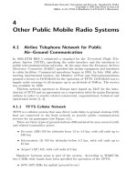
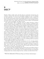
The radio interfaces defined are based on different access technologies. The access technol-
ogy not only defines how the users access the system. The structures defined in Figure 2.1
apparently define radio interfaces that are supported by two different access technologies, but
in fact, what is defined, is a hybrid access technique. This is the case, for example, for IMT-TC
(IMT-Time Code) where the uplink and downlink and the different users are separated based on
transmission on different time slots and on the spreading sequences. Thus W-CDMA (Wide-
band Code Division Multiple Access) is the access technique defined for three of the interfaces,
IMT-DS (IMT-Direct Spread), IMT-MC (IMT-Multi Carrier) and IMT-TC. TDMA (Time
Division Multiple Access) also supports IMT-TC, as has already been mentioned, IMT-SC
(IMT-Single Carrier) and IMT-FT (IMT- Frequency Time). IMT-FT is also supported by a
hybrid access technique based on FDMA (Frequency Division Multiple Access) and TDMA.
Broadband Wireless Mobile: 3G and Beyond. Edited by Willie W. Lu
Copyright
2002 John Wiley & Sons, Ltd.
ISBN: 0-471-48661-2
There is a convergent effort towards the standardization of third-generation mobile systems
that support ITU proposals that will accelerate the IMT2000 standardization activities. Differ-
ent standards development organizations (SDOs), ARIB (Japan), CWTS (China), TIA (USA),
TTA (Korea), TTC (Japan), T1 (USA) and ETSI (Europe) are participating in the development
of these new standards. For that, consortiums and partnerships are being created among them
whose results are standards for the radio interfaces (Figure 2.2).
Broadband Wireless Mobile: 3G and Beyond12
Figure 2.1 Radio interfaces defined for IMT-2000.
Figure 2.2 SDOs working for radio interfaces standardization.
This chapter focuses on the radio interfaces defined with W-CDMA access technology:
IMT-DS, IMT-TC and IMT-MC.
The radio interfaces defined with W-CDMA are being developed thanks to the creation of
the 3G partnership as a multilateral collaboration among SDOs, aiming to facilitate the
development of global technical specifications for 3G mobile systems as an evolution of
the present mobile architectures: GSM and ANSI/TIA/EIA-41.
The 3G partnership is divided into two projects, 3GPP supported by the SDOs that are
actually involved in specification of GSM systems and its evolution, and 3GPP2 that will
comprise the ANSI/TIA/EIA-41 network evolution, involving the corresponding SDOs.
The evolution of both technologies does not imply a convergence in the same solution,
given that, in addition to the partnership projects, work should be done in the direction of
setting the interoperability procedures in order that the ‘family concept’, which is the basis for
IMT-2000, is a reality. This includes not only considering a harmonization in the air interface
specifications, but also a definition of the network interfaces (Figure 2.3). The present mobile
technologies are evolving in such a way that 3GPP is working towards the definition of IMT-
DS and IMT-TC and 3GPP2 for IMT-MC. The radio interfaces are better known as UMTS-
FDD, UMTS-TDD and cdma2000.
2.1.1 3GPP
In December 1998 five market-driven SDOs, ARIB (Japan), ETSI (Europe), T1 (USA), TTA
(Korea) and TTC (Japan), agreed to launch the 3rd Generation Partnership Project (3GPP)
with the posterior incorporation of CWTS (China) in May 1999. The aim of this project is to
cooperate for the production of globally applicable technical specifications for a 3rd genera-
tion mobile system called Universal Mobile Telecommunication System (UMTS) [8], based
on an innovative radio interface Universal Terrestrial Radio Access (UTRA) and evolution of
the GSM core network. The technical specifications will be transposed into relevant standards
by the participating SDOs using their established processes.
UMTS Air Interface 13
Figure 2.3 Definition of architecture interfaces and interoperability.
The technical specifications are focused on four main issues that comprise system and
service aspects, terminals, the core network and the radio access network.
In the first section of this chapter the UMTS radio access network is discussed in detail.
2.1.2 3GPP2
The partnership project 3GPP2 was launched in order to complement the evolution study of
non-GSM systems. 3GPP2 is an effort by the International Committee of the American
National Standards Institute’s (ANSI) to establish the evolution for ANSI/TIA/EIA-41
networks and their Radio Transmission Technologies (RTTs).
2.2 UMTS air interface
The assumed UMTS architecture [9] defines three main functional entities: User Equipment
(UE), UMTS Terrestrial Radio Access Network (UTRAN), and core network. The interfaces
defined between the UE and the UTRAN is the radio interface (Uu) and the interface between
the core network and the UTRAN is called Iu.
The point to focus on are the interfaces: they have been clearly defined in order to set the
interoperability of UEs of different providers with UTRANs from different telecommunica-
tion operators. In particular, this chapter focuses on the radio interface.
The radio interface is characterized through its protocols [9,10] where it can be defined by
two main groupings according to the final purpose service: the user plane protocols and the
control plane protocols. The first carry user data through the access stratum and the second is
responsible for controlling the connections between the UE and the network and the radio
access bearers.
A general protocol architecture splits the radio interface in three layers: a physical layer or
Layer 1, the data link layer (Layer 2) and the network layer or Layer 3. This hierarchical
stratification provides a complete vision of the radio interface, from both the functionality
associated with each of the structured layer to the protocol flow between them.
The purpose of the protocol stack is to set the services to organize the information to
transmit through logical channels whose classifying parameter is the nature of the informa-
tion they carry (i.e. control or traffic information) and map these logical channels into trans-
port channels whose characteristic is how and with what characteristic the information within
each logical channel is transmitted over the radio interface. This how and with whatchar-
acteristic means that for each transport channel there is associated one or more transport
formats, each of them defined by the encoding, interleaving bit rate and mapping onto the
physical channel. Each layer is characterized by the services provided to the higher layers or
entities and the functions that supports them.
Layer 1 [11],[12] supports all functions required for transmission of information on the
physical medium offering information transfer services through the physical channels to higher
layers. This includes preparing the transport channels to be sent through the physical medium,
controlling hypothetical errors and measuring parameters related to the quality of the transfer
service provided: frame error rate, signal to interference ratio, power measurements, etc.
Layer 2 is subdivided into the medium access control (MAC) layer, the radio link control
(RLC) layer, Packet Data Convergence Protocol (PDCP), and Broadcast /Multicast Control
(BMC), each of them providing services to higher layers through their associated functions.
Broadband Wireless Mobile: 3G and Beyond14
The MAC layer handles the transport channels, mapping the logical channels into transport
formats and transferring to peer MAC entities protocol data units. The mapping is controlled
by Layer 3 which is the one that determines the transport format set; consequently MAC layer
should be able to select an appropriate transport format depending on the instantaneous
source rate, the priority handling inside one UE and between UEs. If any multiplexing of
protocol data units (PDUs) into transport blocks are needed it should be performed by the
MAC layer since this functionality is not performed by Layer 1.
RLC provides the transference of higher PDUs to the receiving entity and transfer of user
data with quality of service settings. The transfer can be achieved in three modes: transparent,
unacknowledged and acknowledged, performing for that segmentation, reassemble, conca-
tenation and padding.
PDCP provides transmission of higher PDUs in acknowledged, unacknowledged and
transparent RLC mode, mapping the network protocol into an RLC entity.
BMC provides a broadcast/multicast transmission service in the user plane for common
user data; the broadcast service is supported by a scheduled transmission of cell broadcast
messages handling the radio resources needed.
Layer 3 is the interface between the access stratum of the radio interface and the non-access
stratum. It is subdivided into the radio resource control (RRC) layer which interfaces with
Layer 2 and an upper layer looking after providing access service to higher layers in the non-
access level. Layer 3 provides three different types of services: general control services,
notification services and dedicated control services. The RRC layer handles the control
plane signalling providing measurements reports and radio resource assignments to peer
RRC layers and controlling through feedback information RLC, MAC and physical layers.
Figure 2.4 refers.
Given this brief introduction to the radio interface, next we describe in detail each of the
components.
2.2.1 Layer 1
The physical layer (L1) access scheme is based on Wideband Direct-Sequence Code Division
Multiple Access (WCDMA) technology with two duplex modes: Frequency Division Duplex
(FDD) and Time Division Duplex (TDD). In the FDD mode a physical channel is character-
ized by the code and frequency. Additionally, in the uplink a physical channel is defined by
the relative phase, i.e. if the physical channel is mapped in the quadrature or phase component
of the QPSK modulation. In TDD mode a physical channel is characterized by the code and
time slot. The chip rate is 3.84 Mchips/s, but a fixed chip rate does not imply a fixed service
bit rate. Different symbol rates can be specified for each physical channel applying different
spreading factors (SF) to each symbol.
Table 2.1 presents the possible symbol rates for both duplex modes.
L1 offers data transport services to higher layers. It has two open interfaces: one with MAC
layer through transport channels and the other with RRC layer that controls the configuration
of the physical layer. Each transport channel is characterized by its transport format set. To
each transport format a physical processing is applied to define the physical channel. A
physical channel is defined by a carrier frequency, channelization code, scrambling code,
time interval (starting and stopping transmission time) and relative phase (uniquely in uplink)
and, additionally in TDD, the timeslot and burst type.
UMTS Air Interface 15
The physical layer operates with a hierarchical structure with a basic time interval of 10 ms
called a radio frame which is subdivided into 15 slots. The interpretation of each slot is
different for each of the duplex modes. In FDD within the whole frame is processed the basic
Broadband Wireless Mobile: 3G and Beyond16
Figure 2.4 Protocol Stack for the Radio Interface. 3GPP TSs and TRs are the property of ARIB,
CWTS, ETSI, T1, TTA and TTC who jointly own copyright in them. They are subject to further
modification and are therefore provided to you ‘as is’ for information purposes only. Further use is
strictly prohibited.
Table 2.1 Service symbol rates
FDD TDD
Uplink Downlink Uplink Downlink
SF Symbol
rate (ks/s)
SF Symbol
rate (ks/s)
SF Symbol
rate (ks/s)
SF Symbol
rate (ks/s)
Min. 4 960 4 960 1 3840 1 3840
Max. 256 15 512 7.5 16 240 16 240
unit provided by MAC, the transport block, or several transport blocks, and within each slot a
similar substructure is applicable. In TDD each slot applies not only to determine the dupli-
city needed for uplink and downlink, but also to separate different users. This means that,
unlike FDD, in TDD not only the code domain is being used to separate different users, but
also the time slot. This would somehow justify the high rates provided in TDD mode, since in
this mode the SF does not determine the net physical channel symbol rate, as each physical
channel is not being transmitted in every slot and consequently its average transmission rate is
decreased.
The advantages of TDD vs. FDD are that TDD presents an optimal implementation of
asymmetrical services, where the bandwidth requirements are tighter in the downlink than in
the uplink.
2.2.1.1 FDD
In FDD mode, uplink and downlink transmissions use separate frequency bands. Next, four
main points are treated in order to describe the flow of information from high layers to L1 and
how this information is finally mapped into a physical channel.
Logical, transport and physical channels
Logical channels, which are organized based on what type of information is transferred, are
mapped into transport channels through the MAC layer. Given that the classification of trans-
port channels is based on how the information is transferred, there is not a univocal matching
between them. This is clearer for example observing that the attribute ‘common’ and ‘dedicate’
appears in both logical channels and transport channels, but sometimes a logical dedicated
channel is mapped to a common transport channel and vice versa. The explanation for that is
that a logical dedicated channel contains information for a particular user and can be carried on
a common transport channel together with the information of other users. One step further is the
mapping from transport channels to physical channels. Physical channels are not only deter-
mined by how the information is transmitted but also the type of information transmitted.
The main grouping for transport channels is related to the exclusive use that is made of this
channel; for that we consider dedicated channels (DCH) and common channels. The common
channels are subdivided into Broadcast Channel (BCH), Forward Access Channel (FACH),
Paging Channel (PCH), Random Access Channel (RACH), Common Packet Channel
(CPCH) and Downlink Shared Channel (DSCH).
Two logical channels are mapped into the DCH transport format, the Dedicated Traffic
Channel (DTCH) and the Dedicated Control Channel (DCCH). The first is used for the transfer
of user information and the second for control information. The DCH is an uplink or downlink
channel that can be transmitted over the entire cell or over just part of the cell using beamform-
ing. The DCH would set the transport format for the associated physical channels. Associated
with the DCH, in the uplink there are Dedicated Physical Data Channel (DPDCH) and the
Dedicated Physical Control Channel (DPCCH) corresponding to a mapping in the quadrature
(Q) and phase (I) component, respectively, of the QPSK modulation. In the downlink, the
physical channel is not characterized by the phase modulation in the QPSK so there is just one
Downlink Dedicated Physical Channel (Downlink DPCH) where both control information and
data information are multiplexed in time within the radio frame. The control information that is
UMTS Air Interface 17
transported in the dedicated physical channels is generated at L1. It consists of known pilots for
channel estimation, transmit power control commands, and feedback information.
RACH channel is an uplink transport channel that is always received from the entire cell.
Its main characteristic is that it is characterized by an initial collision risk and open loop
power control. This main characteristic will be useful for the transportation of different
logical channels: Dedicated Control Channel (DCCH), Common Control Channel (CCCH)
and Dedicated Transport Channel (DTCH). The RACH is mapped into the Physical RACH
(PRACH) based on a slotted ALOHA with fast acquisition indication. The random access
transmission can be started at defined time intervals and it consists of one or several pream-
bles of 4096 chips and the message part of duration one or two radio frames. The structure of
the message part is similar to the dedicated physical channel, since the type of information
they transport is the same; what changes is the way the radio resource is accessed. As in the
uplink dedicated physical channels, the data information is mapped in the I component and
the control information inserted in the Q component by L1.
CPCH carries information from DTCH and DCCH logical channels. It is an uplink trans-
port channel associated with a downlink dedicated channel and characterized by the initial
collision risk and inner loop power control. The physical channel with the transport format
associated with the CPCH channel is the Physical CPCH (PCPCH). The transmission is based
on CSMA-CD (Carrier Sense Multiple Access-Collision Detection). As in PRACH the
transmission can be started at defined time intervals and the transmission structure is one
or several preambles, a collision detection preamble, a power control preamble and N multi-
ples of the frame duration containing the message.
The logical channel that broadcasts system control information and cell specific informa-
tion is the BCCH (Broadcast Control Information). One of the transport channel that carries
this information is the BCH, which main characteristic is that it is always transmitted over the
entire cell with a single transport format. The physical channel associated is the Primary
Common Control Physical Channel (P-CCPCH). The transmission rate is fixed within this
channel with a SF ¼ 256. The radio frame structure defined by frames of 10 ms divided in 15
slots is generated here by multiplexing in time the primary and secondary Synchronization
Channel (SCH). The P-CCPCH is transmitted in every slot in the last nine symbols of each
slot.
The other transport channel that carries BCCH information is the FACH. But the transport
characteristics of this channel, transmission over the entire cell or over part using beamform-
ing, the possibility of fast rate change (each 10 ms) and slow power control, match the
requirements for the transportation of many other logical channels: DCCH, CCCH, Common
Traffic Channel (CTCH) and DTCH. FACH mapping into a physical channel is made to the
Secondary Common Control Physical Channel (S-CCPCH) that is described next.
A special control common logical channel is the Paging Control Channel (PCCH). It is a
downlink channel that transmits paging information when the network does not know the cell
location of the UE or the UE is in connect mode using sleep mode procedures. This channel is
mapped to the PCH transport channel which at the physical level corresponds to S-CCPCH.
Both transport channels have similar characteristics although the PCH is always transmitted
over the entire cell and the FACH could be transmitted over just part of the cell. The S-
CCPCH has a frame structure based on the 10 ms frame with 15 slots. Within each slot data
Transport Format Combination Indication (TFCI) field and pilot files are inserted and that is
the key for the main difference between the P-CCPCH and the S-CCPCH; the latter supports
Broadband Wireless Mobile: 3G and Beyond18
the different transport format necessary for the changing rate while the primary transport
format is fixed.
The DSCH is a downlink transport channel shared by different UEs. It is associated with
one or several DCH and it carries information from DTCH and the DCCH. The DSCH could
be transmitted over the entire cell or over part of it using beamforming. The associated
physical channel is the PDSCH. The PDSCH is mapped in the 10 ms radio frame but in a
radio frame different PDSCHs can be allocated using the channelization codes that are
described in the corresponding section. It does not carry control information, but to indicate
that there is information in the PDSCH for a UE either it uses the TFCI of the associated
DPCH or higher layer signalling carried in the DPCH.
The same way that the mapping between logical channels and transport channel is not
biunivocal, there are some physical channels that do not have higher layer associated chan-
nels, i.e. there is not a transport or logical channel that is mapped into them.
Those channels are: Common Pilot Channel (CPICH), Synchronization Channel (SCH),
Acquisition Indicator Channel (AICH), Paging Indicator Channel (PICH), Access Preamble
Acquisition Indication Channel (AP-AICH), CPCH Status Indicator Channel (CSICH) and
Collision-Detection/Channel Assignment Indicator Channel (CD/CA-ICH). All of them are
downlink channels that support functionalities associated explicitly with L1. The CPICH is
used for transmission diversity to provide the UE with a channel where measurements of the
channel state can be performed and later fed back to the base station.
The SCH is used for cell search, synchronization purposes and defining the scrambling
codes for downlink channels. The functionality is performed through two sub-channels.
The primary synchronization channel caries a primary code that is repeated within the
associated radio frame structure in every slot. This code is the same for every cell in the
system. The secondary channel carries a secondary spread over the whole frame. This
secondary code identifies the scrambling sequence for the downlink channels. The
synchronization can be made on a frame basis using the secondary code and on a
slot basis using the primary.
The AICH, AP-AICH and CD/CA-ICH are used to support the uplink channels with
random access, PRACH and PCPCH. CSICH is used to carry CPCH status information
and is directly associated with the AP-AICH. PICH carries paging indicators for the S-
CCPCH.
In Figure 2.5 all the mapping from logical channels to physical is detailed, specifying
which channels are downlink, which uplink and which could be both.
Multiplexing and coding of transport channels
The multiplexing and channel coding functionality is a combination of error detection, error
correction, rate matching, interleaving and multiplexing [30]. This functionality supports
partly the transport services offered to MAC. Information arrives at the multiplexing and
coding unit in transmission time intervals of 10 ms, 20 ms, 40 ms or 80 ms, in basic proces-
sing units called transport blocks. The process the information follows until is ready to be sent
through the channel can be clearly differentiated into two main parts. First is the processing
associated with each transport channel, i.e. setting the information with the corresponding
transport format; here the information is coded, and arranged in order to provide the next step,
multiplexation, with uniform information coming from every transport channel. The multi-
UMTS Air Interface 19
plexation is made over different transport channels. A code-composite transport channel
(CCTCH) is generated and this would be mapped to one or different physical channels.
The steps followed to set the transport format differ when referring to the uplink or down-
link. There are three steps in the process that are common for both: Cyclic Redundancy Code
(CRC), Transport Block Concatenation/Code Block Segmentation, and Channel Coding. In
the uplink the following processes apply: radio frame equalization, first interleaving, radio
frame segmentation and rate matching. In the downlink, after channel coding rate matching,
first insertion of Discontinuous Transmission (DTX) indication bits, first interleaving and
radio frame segmentation are performed. There are two main differences between uplink and
downlink. The first is that, in the downlink, the transmission does not necessarily have to be
continuous; discontinuous transmission bits can be inserted to determine in which time
intervals there is no transmission. The second is that, in the uplink, the rate matching is
made once first interleaving and radio frame segmentation is performed.
In the multiplexing part the steps are transport channel multiplexing, second insertion of
DTX indication bits (only in downlink), physical channel segmentation, second interleaving
and physical channel mapping.
In the CRC attachment a number of bits that are specified by higher layers are inserted in
order to provide the transport block with a redundancy check. The number of bits inserted
belongs to the set {0, 8, 12, 16, 24} and they are obtained through four different cyclic
generator polynomials, respectively.
Once the CRC is performed the serial concatenation of all the transport blocks to be
processed might not give a total length adequate for the next step, coding. The channel
coding defines a maximum size for the block to be coded (code block), depending on the
coding that would be used. The possibilities are, convolutional coding with a maximum code
block of 504 bits, turbo coding with a maximum code block of 5114 bits and no coding. If the
Broadband Wireless Mobile: 3G and Beyond20
Figure 2.5 Mapping of logical channels into physical channels.
total number of bits after concatenation exceeds the corresponding maximum code block
length, segmentation will be performed obtaining a number of code blocks of equal length.
Which of the possible coding schemes is used depends on the transport channel that is being
processed (Table 2.2).
Convolutional coding for both rate 1/2 and 1/3 has a memory order of 9. The generator
polynomials are 561 (octal) and 753 (octal), respectively, for rate 1/2 and 557 (octal), 663
(octal) and 711 (octal) for 1/3.
The turbo coding scheme is a Parallel Concatenated Convolutional Code with two consti-
tuent encoders. Each constituent encoder is a recursive systematic encoder with rate 1/2 and
generator polynomials 15 and 13 (recursive bit) (octal). The systematic bit of the encoder for
the interleaved information is punctured in order to obtain the 1/3 rate. The turbo interleaver
is a design based on a rectangular matrix where intra-row and inter-row permutation is
performed.
Radio frame equalization is needed only in the uplink in order to set the number of bits at
the input to a multiple of the number of radio frames (10 ms) in the transmission time interval.
This operation is not necessary in the downlink since the output of the rate matching that is
the function performed following the channel coding, is already a multiple of the number of
radio frames.
Rate matching repeats or punctures bits in order to match the physical channel bit rate. At
this point in both uplink and downlink the number of bits in the radio frame is already fixed;
considering that the radio frame transmission time interval is 10 ms, the number of bits in the
radio frame is fixed by upper layer signalling with the spreading factor.
First interleaving is performed while setting the transport format. It is a block interleaving
with inter-column permutation. The number of columns and the permutation between them
is fixed and depends on whether the transmission time interval is 10 ms, 20 ms, 40 ms or
80 ms.
The radio frame segmentation is only necessary if the transmission time interval is longer
than 10 ms, then the input sequence is divided and mapped into consecutive radio frames.
Each 10 ms processed radio frame from each of the transport channels that will generate
the CCTCH is delivered to the multiplexing unit. The number of transport channels that can
be multiplexed depends on the nature on the transport channel. The same thing happens with
the number of physical channels that can be generated from the CCTCH after the physical
channel segmentation.
UMTS Air Interface 21
Table 2.2.2 Coding schemes for transport channels in FDD
Transport channel Coding scheme Coding rate
Convolutional coding Turbo coding No coding CC TC
BCH X ––1/2 –
PCH X ––1/2 –
RACH X ––1/2 –
FACH X X X 1/2 1/3 1/3
CPCH X X X 1/2 1/3 1/3
DSCH X X X 1/2 1/3 1/3
DCH X X X 1/2 1/3 1/3
The second interleaving is made for each of the physical channels. It is a block interleaving
with inter-column permutation that randomizes the bit position of the different transport
channels.
The last step is the physical channel mapping, at this point the control information needed
by L1 for channel estimation TFI, etc. is inserted and spreading and modulation is made
accordingly to each physical channel characteristic.
Spreading and modulation
FDD mode characterizes spreading and modulation distinguishing between uplink and down-
link communications [31]. The modulation purpose is mapping the digital sequence (which in
the particular case of the physical channels in the radio interface is the spread sequence) into
signal waveforms that are appropriate for the channel. The modulation used is QPSK.
Coherent demodulation of QPSK makes feasible transporting either the same source infor-
mation doubling the transmission rate or mapping two different sources into the same modu-
lated symbol.
Spreading general purpose is to expand the original signal bandwidth in order to be able to
transmit simultaneously information from different sources; in UMTS these sources are either
different users, different channels associated with different users or base stations. The spread-
ing process in UMTS is divided into two main parts. The first is the channelization operation
where the bit sequence is spread with orthogonal sequences that preserves the orthogonality
between sequences even when the SF are different. The second operation is scrambling where
a scrambling code is applied to the spread signal.
The channelization codes are Orthogonal Variable Spreading Factor (OVSF) codes that in
the uplink preserve the orthogonality among the different user’s channels and in the downlink
between the different channels in the base station. The number of codes available depend on
SF (Figure 2.6).
The generation of OVSF codes allows orthogonality among channels of different rates. The
channelization code allocation in the uplink is fixed and depends on the SF applied to that
particular channel. In the downlink the codes for the Primary Common Control Physical
Channel (P-CCPCH) and the Common Pilot Channel (CPICH) are fixed; the codes for the rest
of physical channels are assigned by UTRAN.
Scrambling codes are different for the uplink and downlink, but in both are applied on a
frame basis, i.e. every frame, that is compound of 38 400 chips, the scrambling sequence is
repeated. This does not mean that the period of the scrambling sequence is 38 400 chips, the
period of the scrambling sequence depends on its application, but every different sequence
would be truncated and repeated in each frame.
In the uplink there are two types of scrambling codes: long and sort. There are 2
24
possible
long scrambling sequences. The different sequences are generated through different initiali-
zation of the 25 memory position shift registers that generate the sequence; the repetition
period of each sequence is every 2
24
bits. For short sequences the number of possible
sequences is the same but they are generated through 3 shift registers of 8 memory positions,
consequently the repetition period is reduced to 256 chips. This means that within one frame
of 38 400 chips, 150 periods of the code are present.
The code allocation made by higher layers allows either short or long codes for mapping of
dedicated channels and paging channels and different compositions of long codes for the rest
of the channels.
Broadband Wireless Mobile: 3G and Beyond22
In downlink the scrambling codes are generated by two shift registers of 18 memory
positions. This leads to n ¼ 0…2
18
2 2 possible codes, but not all of them will be used.
From the whole set of codes a subset of 8192 codes will be used. This subset is classified in
primary and secondary codes. The primary codes are the 512 codes where n is a multiple of
16. The secondary codes associated with a primary code are the 15 codes whose numbering
follows the primary. This classification in primary and secondary codes makes sense since for
each cell a single primary code is assigned; P-CCPCH and CPICH should always be trans-
mitted using the primary code of the cell, being the secondary remaining codes used for the
rest of the downlink physical channels.
How the QPSK symbols are generated and from what information sources differs with the
type of logical channel being mapped and if we are working in the uplink or downlink. In the
uplink, for example, different data channels and a control associated channel can be mapped
into just one physical channel by means of the channelization sequences that would separate
UMTS Air Interface 23
Figure 2.6 OVSF codes generation trees.
the different channels, and the orthogonality provided by the phase (I) and quadrature (Q)
branches of the QPSK symbol.
In the downlink every channel except the synchronization channel is serial to parallel
converted into two branches, I and Q, and each of them spread by the same channelization
code; the complex sequence generated is then multiplied by the complex scrambling
sequence.
Physical procedures
Three physical procedures are described at this point [32]. These procedures define how L1
should work from the point of view of synchronization, power control and transmit diversity.
From the point of view of synchronization, several issues should be achieved, but the
critical ones are from the UE point of view. For that there exists a physical channel SCH
that will exclusively be used by the UE for synchronization purposes. The first step is the cell
search; for that is used a matched filter to the primary synchronization code that is common
for all cells. At this point a slot synchronization is acquired too since this code is repeated
every slot. The frame synchronization is made with the secondary codes at SCH identifying
from all the possible codes which one is being used with a matched filter. Finally the P-
CCPCH can be detected by identifying the primary scrambling code through the CPICH that
carries the channelization code and the primary scrambling code that is unique within the cell.
In the synchronization process, upper layers are informed in both the uplink and downlink
of the synchronization status.
Power control is a physical procedure that handles the transmitted power in both uplink and
downlink. This handling usually sets the control part power (control information inserted at
L1 when physical channel mapping is implemented) while the relative power between control
part and data part is defined by the corresponding transport format. There are two possibi-
lities: open loop power control and inner loop power control. Open loop power control is the
ability of the transmitter in the uplink to set its output power to a specific value. Inner loop
power control is the ability of the transmitter to adjust its output power in accordance with
one or more Transmit Power Control (TPC) commands received. It is used in both the
downlink channel with information provided from the respective uplink channel and the
uplink channel with information from the downlink channel. This counterpart implies that
this power control method can be used where there are related channels in the uplink and
downlink. TPC field is inserted within the frame structure in every physical channel that
supports the inner loop in every slot; that implies that there is the possibility of updating the
transmitted power in every slot. Particularly, there are two functioning ways; in the first the
update is made every slot and in the second it is made every 3 slots for the base station and
every 5 for the UE. Dedicated physical channels and PCHCH support inner loop power
control and open loop is used for RACH power control.
Transmit diversity should be supported in the downlink; there are two main possibilities
that are given when there is information from the uplink of the channel state. In open loop
mode there is no information from the uplink on the channel state and there are two possi-
bilities: Time Switch Transmit Diversity (TSTD) that will be support for the SCH and Space
Time Transmit Diversity (STTD) based on space time block coding. STTD should be
supported for every channel in the downlink except for the SCH. These diversity techniques
are addressed in greater detail in Section 2.5.
Broadband Wireless Mobile: 3G and Beyond24
In close loop mode, the base station has information provided by the UE channel estimates
seen from each antenna. This information is included in one of the control fields of the uplink
dedicated control channel. UE computes this information through measurements in CPICH of
the estimate channels seen from each antenna. This enhancing technique is addressed in more
detail in Section 2.5.
2.2.1.2 TDD
Logical, transport and physical channels
Logical channels
The MAC layer provides data transfer services on logical channels. A set of logical channel
types is defined for different kinds of data transfer services as offered by MAC. Each logical
channel type is defined by what type of information is transferred.
The configuration of logical channel types is depicted in Figure 2.7.
The following control channels are used for transfer of control plane information only:
† Broadcast Control Channel (BCCH)
† Paging Control Channel (PCCH)
† Common Control Channel (CCCH)
† Dedicated Control Channel (DCCH)
† Shared Channel Control Channel (SHCCH).
The following traffic channels are used for the transfer of user plane information only:
† Dedicated Traffic Channel (DTCH)
† Common Traffic Channel (CTCH).
Transport channels
Transport channels are the services offered by Layer 1 to the higher layers. A transport
channel is defined by how and with what characteristics data is transferred over the air
interface. A general classification of transport channels is in two groups:
UMTS Air Interface 25
Figure 2.7 Logical channel structure.
† dedicated channels, using inherent addressing of UE
† common channels, using explicit addressing of UE if addressing is needed.
In TDD there are two types of dedicated transport channels, the Dedicated Channel (DCH)
and the Fast Uplink Signalling Channel (FAUSCH). The DCH is an up- or downlink transport
channel that is used to carry user or control information between the UTRAN and a UE. The
FAUSCH is an uplink channel for signalling and is not yet included yet in the 1999 release of
the specification.
There are six types of control transport channels: BCH, FACH, PCH, RACH, USCH,
DSCH.
† The Broadcast Channel (BCH) is a downlink transport channel that is used to broadcast
system and cell-specific information.
† The Forward Access Channel (FACH) is a downlink transport channel that is used to carry
control information to a mobile station when the system knows the location cell of the
mobile station. The FACH may also carry short user packets.
† The Paging Channel (PCH) is a downlink transport channel that is used to carry control
information to a mobile station when the system does not know the location cell of the
mobile station.
† The Random Access Channel (RACH) is an up link transport channel that is used to carry
control information from mobile station. The RACH may also carry short user packets.
† The Uplink Shared Channel (USCH) is an uplink transport channel shared by several UEs
carrying dedicated control or traffic data.
† The Downlink Shared Channel (DSCH) is a downlink transport channel shared by several
UEs carrying dedicated control or traffic data.
Indicators Indicators are a means of fast low-level signalling entities which are transmitted
without using information blocks sent over transport channels. The meaning of indicators is
implicit to the receiver. The indicator currently defined is the paging indicator.
Physical channels
All physical channels take hierarchical structure with respect to timeslots, radio frames and
system frame numbering (SFN). Depending on the resource allocation, the configuration of
radio frames or timeslots becomes different. All physical channels need guard symbols in
every timeslot. The time slots are used in the sense of a TDMA component to separate
different user signals in the time and the code domain. The physical channel signal format
is presented in Figure 2.8.
A physical channel in TDD is a burst, which is transmitted in a particular timeslot within
allocated radio frames. The allocation can be continuous, i.e. the time slot in every frame is
allocated to the physical channel or discontinuous, i.e. the time slot in a subset of all frames is
allocated only. A burst is the combination of a data part, a midamble and a guard period. The
duration of a burst is one time slot. Several bursts can be transmitted at the same time from
one transmitter. In this case, the data part must use different OVSF channelization codes, but
the same scrambling code. The midamble part has to use the same basic midamble code, but
can use different midambles.
The data part of the burst is spread with a combination of channelization code and scram-
bling code. The channelization code is a OVSF code, that can have a spreading factor of 1, 2,
Broadband Wireless Mobile: 3G and Beyond26
4, 8, or 16. The data rate of the physical channel is depending on the used spreading factor of
the OVSF code used.
The midamble part of the burst can contain two different types of midambles: a short one of
length 256 chips, or a long one of 512 chips. The data rate of the physical channel depends on
the midamble length used.
So a physical channel is defined by frequency, timeslot, channelization code, burst type and
radio frame allocation. The scrambling code and the basic midamble code are broadcast and
may be constant within a cell. When a physical channel is established, a start frame is given.
The physical channels can either be of infinite duration, or a duration for the allocation can be
defined.
The TDMA frame has a duration of 10 ms and is subdivided into 15 time slots (TS) of
2560 £ T
c
duration each. A time slot corresponds to 2560 chips. Each 10 ms frame consists of
15 time slots, each allocated to either the uplink or the downlink. With such flexibility, the
TDD mode can be adapted to different environments and deployment scenarios. In any
configuration at least one time slot has to be allocated for the downlink and at least one
time slot has to be allocated for the uplink.
The DCH is mapped onto the dedicated physical channel. Downlink physical channels
shall use SF ¼ 16. Multiple parallel physical channels can be used to support higher data
rates. These parallel physical channels shall be transmitted using different channelization
codes. Operation with a single code with spreading factor 1 is possible for the downlink
physical channels. The spreading factors that may be used for uplink physical channels range
from 16 down to 1. For each physical channel an individual minimum spreading factor SF
min
is transmitted by means of the higher layers. There are two options that are indicated by
UTRAN:
† the UE shall use the spreading factor SF
min
, independent of the current TFC;
† the UE shall autonomously increase the spreading factor depending on the current TFC.
If the UE autonomously changes the SF, it shall always vary the channelization code along
the lower branch of the allowed OVSF subtree.
For multicode transmission, a UE shall use a maximum of two physical channels per
timeslot simultaneously. These two parallel physical channels shall be transmitted using
different channelization codes. Three types of bursts for dedicated physical channels are
UMTS Air Interface 27
Figure 2.8 Physical channel signal format. 3GPP TSs and TRs are the property of ARIB, CWTS,
ETSI, T1, TTA and TTC who jointly own copyright in them. They are subject to further modification
and are therefore provided to you ‘as is’ for information purposes only. Further use is strictly
prohibited.
defined. All of them consist of two data symbol fields, a midamble and a guard period, the
lengths of which are different for the individual burst types. Thus, the number of data
symbols in a burst depends on the SF and the burst type. The support of all three burst
types is mandatory for the UE. The three different bursts are well suited for different
applications.
The BCH is mapped onto the Primary Common Control Physical Channel (P-CCPCH).
The position (time slot/code) of the P-CCPCH is known from the Physical Synchronization
Channel (PSCH). The P-CCPCH uses fixed spreading with a spreading factor SF ¼ 16. The
P-CCPCH always uses channelization code c
ðk¼1Þ
Q¼16
.
PCH and FACH are mapped onto one or more secondary common control physical chan-
nels (S-CCPCH). In this way the capacity of PCH and FACH can be adapted to the different
requirements. The S-CCPCH uses fixed spreading with a spreading factor SF ¼ 16.
The RACH is mapped onto one or more uplink physical random access channels
(PRACH). In such a way the capacity of RACH can be flexibly scaled depending on the
operator’s need. This description of the physical properties of the PRACH also applies to
bursts carrying other signalling or user traffic if they are scheduled on a time slot which is
(partly) allocated to the RACH. The uplink PRACH uses either spreading factor SF ¼ 16 or
SF ¼ 8.
The set of admissible spreading codes for use on the PRACH and the associated spreading
factors are broadcast on the BCH (within the RACH configuration parameters on the BCH). A
midamble or training sequence is mapped in the burst associated with the PRACH. There
exists a fixed association between the training sequence and the channelization code.
In TDD mode code group of a cell can be derived from the synchronization channel. In
order not to limit the uplink/downlink asymmetry, the SCH is mapped on one or two down-
link slots per frame only. Due to mobile to mobile interference, it is mandatory for public
TDD systems to keep synchronization between base stations. As a consequence of this, a
capture effect concerning SCH can arise. The time offset t
offset
enables the system to overcome
the capture effect.
For Physical Uplink Shared Channel (PUSCH) the burst structure shall be used. User-
specific physical layer parameters like power control, timing advance or directive antenna
settings are derived from the associated channel (FACH or DCH). PUSCH provides the
possibility for transmission of TFCI in uplink.
For Physical Downlink Shared Channel (PDSCH) the burst structure of DPCH shall be
used. User-specific physical layer parameters like power control or directive antenna settings
are derived from the associated channel (FACH or DCH). PDSCH provides the possibility for
transmission of TFCI in downlink.
The Paging Indicator Channel (PICH) is a physical channel used to carry the paging
indicators.
Beacon characteristics of physical channels For the purpose of measurements, physical
channels at particular locations (time slot, code) shall have particular physical characteristics,
called beacon characteristics. Physical channels with beacon characteristics are called beacon
channels. The locations of the beacon channels are called beacon locations. The ensemble of
beacon channels shall provide the beacon function, i.e. a reference power level at the beacon
locations, regularly existing in each radio frame. Thus, beacon channels must be present in
each radio frame.
Broadband Wireless Mobile: 3G and Beyond28
Multiplexing, channel coding and interleaving
Data stream from/to MAC and higher layers (transport block/transport block set) is encoded/
decoded to offer transport services over the radio transmission link [33]. The channel coding
scheme is a combination of error detection, error correcting (including rate matching), and
interleaving and transport channels mapping onto/splitting from physical channels.
In the UTRA-TDD mode, the total number of basic physical channels (a certain time slot,
one spreading code, on a certain carrier frequency) per frame is given by the maximum
number of time slots which is 15 and the maximum number of CDMA codes per time slot.
Figure 2.9 illustrates the overall concept of transport-channel coding and multiplexing.
Data arrives at the coding/multiplexing unit in the form of transport block sets, once every
transmission time interval. The transmission time interval is transport-channel specific from
the set {10 ms, 20 ms, 40 ms, 80 ms}.
The following coding/multiplexing steps can be identified:
† add CRC to each transport block
† TrBk concatenation/code block segmentation
† channel coding
† radio frame size equalization
† interleaving (two steps)
† radio frame segmentation
† rate matching
† multiplexing of transport channels
† physical channel segmentation
† mapping to physical channels.
The coding/multiplexing steps for uplink and downlink are shown in Figure 2.9.
Primarily, transport channels are multiplexed as described above, i.e. into one data stream
mapped on one or several physical channels. However, an alternative way of multiplexing
services is to use multiple CCTrCHs (Coded Composite Transport Channels), which corre-
sponds to having several parallel multiplexing chains as in Figure 2.9 resulting in several data
streams, each mapped to one or several physical channels.
Error detection is provided on transport blocks through a Cyclic Redundancy Check
(CRC). The size of the CRC is 24, 16, 12, 8 or 0 bits and it is signalled from higher layers
what CRC size that should be used for each transport channel.
All transport blocks in a TTI are serially concatenated. If the number of bits in a TTI is
larger than the maximum size of a code block, then code block segmentation is performed
after the concatenation of the transport blocks. The maximum size of the code blocks depends
on whether convolutional, turbo coding or no coding is used for the TrCH.
The bits input to the transport block concatenation are denoted by b
im1
; b
im2
; b
im3
; …; b
imB
i
where i is the TrCH number, m is the transport block number, and B
i
is the number of bits in
each block (including CRC). The number of transport blocks on TrCH i is denoted by M
i
. The
bits after concatenation are denoted by x
i1
; x
i2
; x
i3
; …; x
iX
i
, where i is the TrCH number and
X
i
¼ M
i
B
i
.
Segmentation of the bit sequence from transport block concatenation is performed if Xi .
Z. The code blocks after segmentation are of the same size. The number of code blocks on
TrCH i is denoted by Ci. If the number of bits input to the segmentation, Xi, is not a multiple
UMTS Air Interface 29
Broadband Wireless Mobile: 3G and Beyond30
Figure 2.9 Transport channel multiplexing structure for uplink and downlink. 3GPP TSs and TRs are
the property of ARIB, CWTS, ETSI, T1, TTA and TTC who jointly own copyright in them. They are
subject to further modification and are therefore provided to you ‘as is’ for information purposes only.
Further use is strictly prohibited.
of Ci, filler bits are added to the beginning of the first block. If turbo coding is selected and
Xi , 40, filler bits are added to the beginning of the code block. The filler bits are transmitted
and they are always set to 0.
Code blocks are delivered to the channel coding block. They are denoted by
o
ir1
; o
ir2
; o
ir3
; …; o
irK
i
, where i is the TrCH number, r is the code block number, and K
i
is
the number of bits in each code block. The number of code blocks on TrCH i is denoted by C
i
.
After encoding the bits are denoted by y
ir1
; y
ir2
; y
ir3
; …; y
irY
i
, where Y
i
is the number of
encoded bits. The relation between o
irk
and y
irk
and between K
i
and Y
i
is dependent on the
channel coding scheme.
The following channel coding schemes can be applied to transport channels:
† convolutional coding
† turbo coding
† no coding.
The coding schemes applied are the same as for the FDD mode already described.
Radio frame size equalization is padding the input bit sequence in order to ensure that the
output can be segmented in F
i
data segments of the same size.
The input bit sequence to the radio frame size equalization is denoted by c
i1
; c
i2
; c
i3
; …; c
iE
i
,
where i is the TrCH number and E
i
the number of bits. The output bit sequence is denoted by
t
i1
; t
i2
; t
i3
; …; t
iT
i
, where T
i
is the number of bits. The output bit sequence is derived as follows:
t
ik
¼ c
ik
for k ¼ 1; …; E
i
ð1Þ
and
t
ik
¼ {0; 1} for k ¼ E
i
1 1; …; T
i
; if E
i
, T
i
ð2Þ
where
T
i
¼ F
i
£ N
i
ð3Þ
and
N
i
¼ E
i
=F
i
de
ð4Þ
is the number of bits per segment after size equalization.The first interleaving is a block
interleaver with inter-column permutations. The input bit sequence to the block interleaver is
denoted by x
i;1
; x
i;2
; x
i;3
; …; x
i;X
i
, where i is the TrCH number and X
i
is the number of bits. Here
X
i
is guaranteed to be an integer multiple of the number of radio frames in the TTI. The output
bit sequence from the block interleaver is derived as follows:
† NUMBEREDSelect the number of columns C1 from Table 2.3 depending on the TTI. The
columns are numbered 0,1,…C1 2 1 from left to right.
† Determine the number of rows of the matrix, R1 defined as:
R1 ¼ X
i
=C1 ð5Þ
The rows of the matrix are numbered 0,1,…,R1 2 1 from top to bottom.
† Write the input bit sequence into the R1 £ C1 matrix row by row starting with bit x
i;1
in
column 0 of row 0 and ending with bit x
i;ðR1£C1Þ
in column C1 2 1 of row R1 2 1:
UMTS Air Interface 31
x
i;1
x
i;2
x
i;3
…
x
i;ðC111Þ
x
i;ðC112Þ
x
i;ðC113Þ
…
.
.
.
.
.
.
.
.
.
…
x
i;ððR121Þ£C111Þ
x
i;ððR121Þ£C112Þ
x
i;ððR121Þ£C113Þ
…
x
i;C1
x
i;ð2£C1Þ
.
.
.
x
i;ðR1£C1Þ
2
6
6
6
6
6
6
6
4
3
7
7
7
7
7
7
7
5
ð6Þ
† Perform the inter-column permutation for the matrix based on the pattern
P1
C1
j
ÀÁ
j[ 0;1;…;C121
fg
shown in Table 2.3, where P1
C1
(j) is the original column position
of the jth permuted column. After permutation of the columns, the bits are denoted by y
i,k
:
y
i;1
y
i;ðR111Þ
y
i;ð2£R111Þ
…
y
i;2
y
i;ðR112Þ
y
i;ð2£R112Þ
…
.
.
.
.
.
.
.
.
.
…
y
i;R1
y
i;ð2£R1Þ
y
i;ð3£R1Þ
…
y
i;ððC121Þ£R111Þ
y
i;ððC121Þ£R112Þ
.
.
.
y
i;ðC1£R1Þ
2
6
6
6
6
6
6
6
4
3
7
7
7
7
7
7
7
5
ð7Þ
† Read the output bit sequence y
i;1
; y
i;2
; y
i;3
; …; y
i;ðC1£R1Þ
of the block interleaver column by
column from the inter-column permuted R1 £ C1 matrix. Bit y
i;1
corresponds to row 0 of
column 0 and bit y
i;ðR1£C1Þ
corresponds to row R1 2 1 of column C1 2 1.
When the transmission time interval is longer than 10 ms, the input bit sequence is
segmented and mapped onto consecutive F
i
radio frames. Following radio frame size equal-
ization the input bit sequence length is guaranteed to be an integer multiple of F
i
.
Rate matching means that bits on a TrCH are repeated or punctured. Higher layers assign a
rate-matching attribute for each TrCH. This attribute is semi-static and can only be changed
through higher layer signalling. The rate-matching attribute is used when the number of bits
to be repeated or punctured is calculated. The number of bits on a TrCH can vary between
different transmission time intervals. When the number of bits between different transmission
time intervals is changed, bits are repeated to ensure that the total bit rate after TrCH multi-
plexing is identical to the total channel bit rate of the allocated physical channels. If no bits
Broadband Wireless Mobile: 3G and Beyond32
Table 2.3 Inter-column permutation patterns for first interleaving
TTI
(ms)
Number of
columns C1
Inter-column permutation patterns
kP1
C1
(0), P1
C1
(1),…,P1
C1
(C1-1)l
10 1 k0l
20 2 k0,1l
40 4 k0,2,1,3l
80 8 k0,4,2,6,1,5,3,7l
are input to the rate matching for all TrCHs within a CCTrCH, the rate matching shall output
no bits for all TrCHs within the CCTrCH. Puncturing can be used to minimize the required
transmission capacity. The maximum amount of puncturing that can be applied is 1-PL; PL is
signalled from higher layers. The possible values for N
data
depend on the number of physical
channels P
max,
allocated to the respective CCTrCH, and on their characteristics (spreading
factor, length of midamble and TFCI, usage of TPC and multiframe structure).
Every 10 ms, one radio frame from each TrCH is delivered to the TrCH multiplexing.
These radio frames are serially multiplexed into a coded composite transport channel
(CCTrCH).
When more than one PhCH is used, physical channel segmentation divides the bits among
the different PhCHs.
The second interleaving is a block interleaver and consists of bits input to a matrix with
padding, the inter-column permutation for the matrix and bits output from the matrix with
pruning. The second interleaving can be applied jointly to all data bits transmitted during one
frame, or separately within each timeslot, on which the CCTrCH is mapped. The selection of
the second interleaving scheme is controlled by higher layers.
The bits after physical channel mapping are denoted by w
p;1
; w
p;2
; …; w
p;U
p
, where p is the
PhCH number and U
p
is the number of bits in one radio frame for the respective PhCH. The
bits w
p,k
are mapped to the PhCHs so that the bits for each PhCH are transmitted over the air in
ascending order with respect to k.
Different transport channels can be encoded and multiplexed together into one Coded
Composite Transport Channel (CCTrCH). There are two types of CCTrCH:
† CCTrCH of dedicated type, corresponding to the result of coding and multiplexing of one
or several DCH.
† CCTrCH of common type, corresponding to the result of the coding and multiplexing of a
common channel, i.e. RACH and USCH in the uplink and DSCH, BCH, FACH or PCH in
the downlink, respectively.
Transmission of TFCI is possible for CCTrCH containing transport channels of:
† dedicated type
† USCH type
† DSCH type
† FACH and/or PCH type.
The following CCTrCH combinations in the uplink are allowed simultaneously:
† several CCTrCH of dedicated type
† several CCTrCH of common type.
Allowed CCTrCH combinations on the downlink:
† several CCTrCH of dedicated type
† several CCTrCH of common type.
Transport format detection can be performed both with and without Transport Format
Combination Indicator (TFCI). If a TFCI is transmitted, the receiver detects the transport
format combination from the TFCI. When no TFCI is transmitted, so-called blind transport
format detection may be used, i.e. the receiver side uses the possible transport format combi-
UMTS Air Interface 33
nations as a priori information. Blind transport format detection is optional both in the UE and
the UTRAN. Therefore, for all CCTrCH, a TFCI shall be transmitted, including the possi-
bility of a TFCI length zero, if only one TFC is defined. The Transport Format Combination
Indicator (TFCI) informs the receiver of the transport format combination of the CCTrCHs.
As soon as the TFCI is detected, the transport format combination, and hence the individual
transport channels’ transport formats are known, and decoding of the transport channels can
be performed.
Encoding of the TFCI depends on its length, whether there are 6–10 bits of TFCI or if there
are less than 6 bits. TFCI is encoded by the (32,10) sub-code of second order Reed–Muller
code. The code words of the (32,10) sub-code of second order Reed–Muller code are linear
combination of some among 10 basis sequences.
The paging indicator P
q
is an identifier to instruct the UE whether there is a paging message
for the groups of mobiles that are associated with the PI, calculated by higher layers, and the
associated paging indicator P
q
. The length L
PI
of the paging indicator is L
PI
¼ 2, L
PI
¼ 4or
L
PI
¼ 8 symbols.
The TPC command is an identifier sent in uplink transmission only, to instruct NodeB
whether Tx power has to be increased or decreased. The length of the TPC command is one
symbol.
Spreading and modulation
In Table 2.4, a separation between the data modulation and the spreading modulation has
been made [34].
The symbol duration T
S
depends on the spreading factor Q and the chip duration T
C
: T
s
¼
Q £ T
c
, where T
c
¼ 1/chip rate.
For any burst type the data modulation is performed to the bits from the output of the
physical channel mapping procedure and always combines two consecutive binary bits to a
complex valued data symbol. Each user burst has two data carrying parts, termed data blocks:
d
ðk:iÞ
¼ð
d
ðk;iÞ
1
;
d
ðk;iÞ
2
; …;
d
ðk;iÞ
N
K
Þ
T
; i ¼ 1; 2; k ¼ 1; …; K ð8Þ
N
k
is the number of symbols per data field for the user k. Data block d
ðk;1Þ
is transmitted before
the midamble and data block d
ðk;2Þ
after the midamble. Each of the N
k
data symbols
d
ðk;iÞ
n
, i ¼
1,2, k ¼ 1,…,K, n ¼ 1,…,N
k
, of equation (1) has the symbol duration T
ðkÞ
s
¼ Q
k
T
c
as already
given.
The data modulation is QPSK, thus the data symbols
d
ðk;iÞ
n
are generated from two conse-
cutive data bits from the output of the physical channel mapping procedure:
Broadband Wireless Mobile: 3G and Beyond34
Table 2.4 Basic modulation parameters
Chip rate Same as FDD chip rate:
3.84 Mchip/s
Low chip rate:
1.28 Mchip/s
Data modulation QPSK QPSK
Spreading characteristics Orthogonal; Q chips/symbol,
where Q ¼ 2
p
,0# p # 4
Orthogonal; Q chips/symbol,
where Q ¼ 2
p
,0# p # 4
b
ðk;iÞ
l;n
[ {0; 1}; l ¼ 1; 2; k ¼ 1; …; K; n ¼ 1; …; N
k
; i ¼ 1; 2 ð9Þ
using the mapping to complex symbols in Table 2.5.
The mapping corresponds to a QPSK modulation of the interleaved and encoded data bits
b
ðk;iÞ
l;n
of equation (9).
In case of PRACH burst type, the definitions in for burst types 1 and 2 apply with a
modified number of symbols in the second data block. For the PRACH burst type, the number
of symbols in the second data block d
ðk;2Þ
is decreased by 96=Q
K
symbols.
For spreading, each complex valued data symbol
d
ðk;iÞ
n
of equation (1) is spread with a real
valued channelization code c
ðkÞ
of length Q
k
[ {1; 2; 4; 8; 16}. The resulting sequence is then
scrambled by a complex sequence
n of length 16.
The elements c
ðkÞ
q
, k ¼ 1,…,K, q ¼ 1,…,Q
k
, of the real valued channelization codes
c
ðkÞ
¼ðc
ðkÞ
1
; c
ðkÞ
2
; …; c
ðkÞ
Q
k
; k ¼ 1; …; K ð10Þ
shall be taken from the set
V
c
¼ {1; 21} ð11Þ
The c
ðkÞ
Q
k
are Orthogonal Variable Spreading Factor (OVSF) codes, mixing in the same time-
slot channels with different spreading factors while preserving the orthogonality. As
described above, the OVSF codes can be defined using the code tree of Figure 2.6. All
codes within the code tree cannot be used simultaneously in a given timeslot. A code can
be used in a timeslot if and only if no other code on the path from the specific code to the root
of the tree or in the sub-tree below the specific code is used in this timeslot. This means that
the number of available codes in a slot is not fixed but depends on the rate and spreading
factor of each physical channel. The spreading factor goes up to Q
MAX
¼ 16.
The spreading of data by a real valued channelization code c
ðkÞ
of length Q
k
is followed by a
cell-specific complex scrambling sequence
n ¼
n
1
;
n
2
; :::; C
n
16
ÀÁ
. The elements
n
i
; i ¼
1; :::; 16 of the complex valued scrambling codes shall be taken from the complex set:
V
n
¼ {1; j; 21; 2j} ð12Þ
In equation (12) the letter j denotes the imaginary unit. A complex scrambling code
n is
generated from the binary scrambling codes
n
¼ð
n
1
;
n
2
; …;
n
16
Þ of length 16 described in
[34]. The relation between the elements
n and n is given by
UMTS Air Interface 35
Table 2.5 Complex QPSK mapping
Consecutive binary bit pattern Complex symbol
b
ðk;jÞ
l;n
b
ðk;iÞ
2;n
d
ðk;iÞ
n
00 1j
01 11
10 21
11 2j