Tài liệu GSM Switching, Services and Protocols P5 docx
Bạn đang xem bản rút gọn của tài liệu. Xem và tải ngay bản đầy đủ của tài liệu tại đây (936.76 KB, 37 trang )
Air Interface ± Physical
Layer
The GSM physical layer, which resides on the ®rst of the seven layers of the OSI Reference
Model [55], contains very complex functions. The physical channels are de®ned here by a
TDMA multiple access scheme. On top of the physical channels, a series of logical
channels are de®ned, which are transmitted in the time slots of the physical channels.
Logical channels perform a multiplicity of functions, such as payload transport, signaling,
broadcast of general system information, synchronization, and channel assignment.
The structure of this chapter is as follows: In Section 5.1, we describe the logical channels.
This serves as a foundation for understanding the signaling procedures at the air interface.
The realization of the physical channels, including GSM modulation, multiple access,
duplexing, and frequency hopping follows in Section 5.2. Next, Section 5.3 covers
synchronization. The mapping of logical onto physical channels follows in Section 5.4,
where the higher-level multiplexing of logical channels into multiframes is also covered.
Section 5.5 contains a discussion of the most important control mechanisms for the air
interface (channel measurement, power control, disconnection, and cell selection). The
conclusion of the chapter is a power-up scenario with the sequence of events occurring,
from when a mobile station is turned on to when it is in a synchronized state ready to
transmit (Section 5.6).
5.1 Logical Channels
On Layer 1 of the OSI Reference Model, GSM de®nes a series of logical channels, which
are made available either in an unassigned random access mode or in a dedicated mode
assigned to a speci®c user. Logical channels are divided into two categories (Table 5.1):
Traf®c channels and signaling (control) channels.
5.1.1 Traf®c Channels
The Traf®c Channels (TCHs) are used for the transmission of user payload data (speech,
fax, data). They do not carry any control information of Layer 3. Communication over a
TCH can be circuit-switched or packet-switched. In the circuit-switched case, the TCH
provides a transparent data connection or a connection that is specially treated according to
5
GSM Switching, Services and Protocols: Second Edition. Jo
È
rg Eberspa
È
cher,
Hans-Jo
È
rg Vo
È
gel and Christian Bettstetter
Copyright q 2001 John Wiley & Sons Ltd
Print ISBN 0-471-49903-X Online ISBN 0-470-84174-5
the carried service (e.g. telephony). For the packet-switched mode, the TCH carries user
data of OSI Layers 2 and 3 according to the recommendations of the X.25 standard or
similar standard packet protocols.
A TCH may either be fully used (full-rate TCH, TCH/F) or be split into two half-rate
channels (half-rate TCH, TCH/H), which can be allocated to different subscribers. Follow-
ing ISDN terminology, the GSM traf®c channels are also designated as Bm channel
(mobile B channel) or Lm channel (lower-rate mobile channel, with half the bit rate). A
Bm channel is a TCH for the transmission of bit streams of either 13 kbit/s of digitally
coded speech or of data streams at 14.5, 12, 6, or 3.6 kbit/s. Lm channels are TCH channels
with less transmission bandwidth than Bm channels and transport speech signals of half the
bit rate (TCH/H) or bit streams for data services with 6 or 3.6 kbit/s.
5.1.2 Signalling Channels
The control and management of a cellular network demands a very high signaling effort.
Even when there is no active connection, signaling information (for example location
update information) is permanently transmitted over the air interface. The GSM signaling
channels offer a continuous, packet-oriented signaling service to MSs in order to enable
them to send and receive messages at any time over the air interface to the BTS. Following
ISDN terminology, the GSM signaling channels are also called Dm channels (mobile D
channel). They are further divided into: Broadcast Channel (BCH), Common Control
Channel (CCCH), and Dedicated Control Channel (DCCH) (see Table 5.1).
The unidirectional Broadcast Channels are used by the Base Station Subsystem (BSS) to
5 Air Interface ± Physical Layer
58
Table 5.1: Classi®cation of logical channels in GSM
Group Channel Function Direction
Traf®c channel Traf®c channel (TCH) TCH/F, Bm Full rate TCH MS $ BSS
TCH/H, Lm Half rate TCH MS $ BSS
Signaling Broadcast channel BCCH Broadcast control MS Ã BSS
channels (Dm) FCCH Frequency correction MS Ã BSS
SCH Synchronization MS Ã BSS
Common control
channel (CCCH)
RACH Random access MS ! BSS
AGCH Access grant MS Ã BSS
PCH Paging MS Ã BSS
NCH Noti®cation MS Ã BSS
Dedicated control
channel (DCCH)
SDCCH Stand-alone dedicated
control
MS $ BSS
SACCH Slow associated control MS $ BSS
FACCH Fast associated control MS $ BSS
broadcast the same information to all MSs in a cell. The group of Broadcast Channels
consists of three channels:
² Broadcast Control Channel (BCCH): On this channel, a series of information elements
is broadcast to the MSs which characterize the organization of the radio network, such
as radio channel con®gurations (of the currently used cell as well as of the neighboring
cells), synchronization information (frequencies as well as frame numbering), and
registration identi®ers (LAI, CI, BSIC). In particular, this includes information about
the structural organization (formats) of the CCCH of the local BTS. The BCCH is
broadcast on the ®rst frequency assigned to the cell (the so-called BCCH carrier).
² Frequency Correction Channel (FCCH): On the FCCH, information about correction of
the transmission frequency is broadcast to the MSs; see Section 5.2.2 (frequency
correction burst).
² Synchronization Channel (SCH): The SCH broadcasts information to identify a BTS,
i.e. Base Station Identity Code (BSIC); see Section 3.2.9. The SCH also broadcasts data
for the frame synchronization of an MS, i.e. Reduced Frame Number (RFN) of the
TDMA frame; see Section 5.3.1.
FCCH and SCH are only visible within protocol Layer 1, since they are only needed for the
operation of the radio subsystem. There is no access to them from Layer 2. In spite of this
fact, the SCH messages contain data which are needed by Layer 3 for the administration of
radio resources. These two channels are always broadcast together with the BCCH.
The CCCH is a point-to-multipoint signaling channel to deal with access management
functions. This includes the assignment of dedicated channels and paging to localize a
mobile station. It comprises the following:
² Random Access Channel (RACH): The RACH is the uplink portion of the CCCH. It is
accessed from the mobile stations in a cell without reservation in a competitive multi-
ple-access mode using the principle of slotted Aloha [4], to ask for a dedicated signaling
channel (SDCCH) for exclusive use by one MS for one signaling transaction.
² Access Grant Channel (AGCH): The AGCH is the downlink part of the CCCH. It is
used to assign an SDCCH or a TCH to a mobile station.
² Paging Channel (PCH): The PCH is also part of the downlink of the CCCH. It is used
for paging to ®nd speci®c mobile stations.
² Noti®cation Channel (NCH): The NCH is used to inform mobile stations about incom-
ing group and broadcast calls.
The last type of signaling channel, the DCCH is a bidirectional point-to-point signaling
channel. An Associated Control Channel (ACCH) is also a dedicated control channel, but
it is assigned only in connection with a TCH or an SDCCH. The group of Dedicated/
Associated Control Channels (D/ACCH) comprises the following:
² Stand-alone Dedicated Control Channel (SDCCH): The SDCCH is a dedicated point-
to-point signaling channel (DCCH) which is not tied to the existence of a TCH
(``stand-alone''), i.e. it is used for signaling between an MS and the BSS when there
is no active connection. The SDCCH is requested from the MS via the RACH and
assigned via the AGCH. After the completion of the signaling transaction, the SDCCH
is released and can be reassigned to another MS. Examples of signaling transactions
5.1 Logical Channels
59
which use an SDCCH are the updating of location information or parts of the connection
setup until the connection is switched through (see Figure 5.1).
² Slow Associated Control Channel (SACCH): An SACCH is always assigned and used
with a TCH or an SDCCH. The SACCH carries information for the optimal radio
operation, e.g. commands for synchronization and transmitter power control and reports
on channel measurements (Section 5.5). Data must be transmitted continuously over the
SACCH since the arrival of SACCH packets is taken as proof of the existence of the
physical radio connection (Section 5.5.3). When there is no signaling data to transmit,
the MS sends a measurement report with the current results of the continuously
conducted radio signal level measurements (Section 5.5.1).
² Fast Associated Control Channel (FACCH): By using dynamic pre-emptive multiplex-
ing on a TCH, additional bandwidth can be made available for signaling. The signaling
channel created this way is called FACCH. It is only assigned in connection with a
TCH, and its short-time usage goes at the expense of the user data transport.
In addition to these channels, a Cell Broadcast Channel (CBCH) is de®ned, which is used
to broadcast the messages of the Short Message Service Cell Broadcast (SMSCB). The
CBCH shares a physical channel together with the SDCCH.
5 Air Interface ± Physical Layer
60
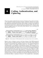
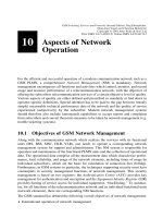
Figure 5.1: Logical channels and signaling (connection setup for an incoming call)
5.1.3 Example: Connection Setup for Incoming Call
Figure 5.1 shows an example for an incoming call connection setup at the air interface. It is
illustrated how the various logical channels are used in principle. The mobile station is
called via the PCH and requests a signaling channel on the RACH. It gets the SDCCH
through an immediate assignment message on the AGCH. Then follow authentication,
start of ciphering, and start of setup over the SDCCH. An assignment command message
gives the traf®c channel to the mobile station, which acknowledges its receipt on the
FACCH of this traf®c channel. The FACCH is also used to continue the connection setup.
5.1.4 Bit Rates, Block Lengths, and Block Distances
Table 5.2 gives an overview of the logical channels of Layer 1, the available bit rates,
block lengths used, and the intervals between transmission of blocks. The 14.4 kbit/s data
service has been standardized in further GSM standardization phases. Notice that the
logical channels can suffer from substantial transmission delays depending on the respec-
tive use of forward error correction (channel coding and interleaving, see Section 6.2 and
Table 6.8).
5.1 Logical Channels
61
Table 5.2: Logical channels of GSM Protocol Layer 1
Channel type Net data throughput
(in kbit/s)
Block length
(in bit)
Block distance
(in ms)
TCH (full-rate speech) 13.0 182 1 78 20
TCH (half-rate speech) 5.6 95 1 17 20
TCH (data, 14.4 kbit/s) 14.5 290 20
TCH (data, 9.6 kbit/s) 12.0 60 5
TCH (data, 4.8 kbit/s) 6.0 60 10
TCH (data, # 2.4 kbit/s) 3.6 72 10
FACCH full rate 9.2 184 20
FACCH half rate 4.6 184 40
SDCCH 598/765 184 3060/13
SACCH (with TCH) 115/300 168 1 16 480
SACCH (with SDCCH) 299/765 168 1 16 6120/13
BCCH 598/765 184 3060/13
AGCH n £ 598/765 184 3060/13
NCH m £ 598/765 184 3060/13
PCH p £ 598/765 184 3060/13
RACH r £ 27/765 8 3060/13
CBCH 598/765 184 3060/13
5.1.5 Combinations of Logical Channels
Not all logical channels can be used simultaneously at the radio interface. They can only be
deployed in certain combinations and on certain physical channels. GSM has de®ned
several channel con®gurations, which are realized and offered by the base stations
(Table 5.3). As already mentioned before, an SACCH is always allocated either with a
TCH or with an SDCCH, which accounts for the attribute ``associated''.
Depending on its current state, a mobile station can only use a subset of the logical
channels offered by the base station. It uses the channels only in the combinations indi-
cated in Table 5.4. The combination M1 is used in the phase when no physical connection
exists, i.e. immediately after the power-up of the mobile station or after a disruption due to
unsatisfactory radio signal conditions. Channel combinations M2 and M3 are used by
active mobile stations in standby mode. In phases requiring a dedicated signaling channel,
a mobile station uses the combination M4, whereas M5 to M8 are used when there is a
traf®c channel up. M8 is a multislot combination (an MS transmits on several physical
5 Air Interface ± Physical Layer
62
Table 5.3: Channel combinations offered by the base station
Table 5.4: Channel combinations used by the base station
channels), where n denotes the number of bidirectional channels, and m denotes the
number of unidirectional channels (n 1; ¼; 8, m 0; ¼; 7, n 1 m 1; ¼; 8).
5.2 Physical Channels
After discussing the logical channels and their tasks, we now deal with the physical
channels, which transport the logical channels via the air interface. We ®rst describe the
GSM modulation technique (Section 5.2.1), followed by the multiplexing structure
(Section 5.2.2): GSM is a multicarrier TDMA system, i.e. it employees a combination
of FDMA and TDMA for multiple access. This section also covers the explanation of the
radio bursts. Finally, Section 5.2.3 brie¯y describes the (optional) frequency hopping
technique, which has been standardized to reduce interference.
5.2.1 Modulation
The modulation technique used on the radio channel is Gaussian Minimum Shift Keying
(GMSK). GMSK belongs to a family of continuous-phase modulation procedures, which
have the special advantages of a narrow transmitter power spectrum with low adjacent
channel interference on the one hand and a constant amplitude envelope on the other hand,
which allows use of simple ampli®ers in the transmitters without special linearity require-
ments (class C ampli®ers). Such ampli®ers are especially inexpensive to manufacture,
have high degree of ef®ciency, and therefore allow longer operation on a battery charge
[15,64].
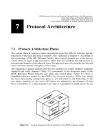
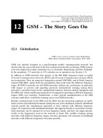
The digital modulation procedure for the GSM air interface comprises several steps for the
generation of a high-frequency signal from channel-coded and enciphered data blocks
(Figure 5.2).
The data d
i
arrives at the modulator with a bit rate of 1625/6 kbit/s 270.83 kbit/s (gross
data rate) and are ®rst differential-coded:
^
d
i
d
i
1 d
i21
ÀÁ
mod 2; d
i
[ 0; 1
From this differential data, the modulation data is formed, which represents a sequence of
Dirac pulses:
a
i
1 2 2
^
d
i
This bipolar sequence of modulation data is fed into the transmitter ®lter ± also called a
frequency ®lter ± to generate the phase w(t) of the modulation signal. The impulse response
g(t) of this linear ®lter is de®ned by the convolution of the impulse response h(t)ofa
5.2 Physical Channels
63
Figure 5.2: Steps of GSM digital modulation
Gaussian low-pass with a rectangular step function:
gtht p rectt=T
rectt=T
1=T for jtj , T=2
0 for jtj $ T=2
@
ht
1
2
p
p
s
T
exp
2t
2
2
s
2
T
2
23
;
s
ln2
p
2
p
BT
; BT 0:3
In the equations above, B is the 3 dB bandwidth of the ®lter h(t) and T the bit duration of
the incoming bit stream. The rectangular step function and the impulse response of the
Gaussian lowpass are shown in Figure 5.3, and the resulting impulse response g(t) of the
transmitter ®lter is given in Figure 5.4 for some values of BT. Notice that with decreasing
5 Air Interface ± Physical Layer
64
Figure 5.3: Impulse responses for the building blocks of the GMSK transmitter ®lter
Figure 5.4: Impulse response g(t) of the frequency ®lter (transmitter ®lter)
BT the impulse response becomes broader. For BT ! 1 it converges to the rect( ) func-
tion.
In essence, this modulation consists of a Minimum Shift Keying (MSK) procedure, where
the data is ®ltered through an additional Gaussian lowpass before Continuous Phase
Modulation (CPM) with the rectangular ®lter [15]. Accordingly it is called Gaussian
MSK (GMSK). The Gaussian lowpass ®ltering has the effect of additional smoothing,
but also of broadening the impulse response g(t). This means that, on the one hand the
power spectrum of the signal is made narrower, but on the other hand the individual
impulse responses are ``smeared'' across several bit durations, which leads to increased
intersymbol interference. This partial-response behavior has to be compensated for in the
receiver by means of an equalizer [15].
The phase of the modulation signal is the convolution of the impulse response g(t) of the
frequency ®lter with the Dirac impulse sequence a
i
of the stream of modulation data:
w
t
i
a
i
ph
t 2 iT
2 1
gudu
with the modulation index at h 1/2, i.e. the maximal phase shift is p/2 per bit duration.
Accordingly, GSM modulation is designated as 0.3-GMSK with a p/2 phase shift. The
phase w(t) is now fed to a phase modulator. The modulated high-frequency carrier signal
can then be represented by the following expression, where E
c
is the energy per bit of the
modulated data rate, f
0
the carrier frequency, and w
0
is a random phase component staying
constant during a burst:
xt
2E
c
T
r
cos2
p
f
0
t 1
w
t 1
w
0
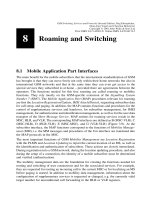
5.2.2 Multiple Access, Duplexing, and Bursts
On the physical layer (OSI Layer 1), GSM uses a combination of FDMA and TDMA for
multiple access. Two frequency bands 45 MHz apart have been reserved for GSM opera-
tion (Figure 5.5): 890±915 MHz for transmission from the mobile station, i.e. uplink, and
935±960 MHz for transmission from the base station, i.e. downlink. Each of these bands of
25 MHz width is divided into 124 single carrier channels of 200 kHz width. This variant of
FDMA is also called Multi-Carrier (MC). In each of the uplink/downlink bands there
remains a guardband of 200 kHz. Each Radio Frequency Channel (RFCH) is uniquely
numbered, and a pair of channels with the same number form a duplex channel with a
duplex distance of 45 MHz (Figure 5.5).
A subset of the frequency channels, the Cell Allocation (CA), is allocated to a base station,
i.e. to a cell. One of the frequency channels of the CA is used for broadcasting the
synchronization data (FCCH and SCH) and the BCCH. Therefore this channel is also
called the BCCH Carrier (see Section 5.4). Another subset of the cell allocation is allo-
cated to a mobile station, the Mobile Allocation (MA). The MA is used among others for
the optional frequency hopping procedure (Section 5.2.3). Countries or areas which allow
more than one mobile network to operate in the same area of the spectrum must have a
5.2 Physical Channels
65
licensing agency which distributes the available frequency number space (e.g. the Federal
Communication Commission in the USA or the ``Regulierungsbeho
È
rde fu
È
r Telekommu-
nikation und Post'' in Germany), in order to avoid collisions and to allow the network
operators to perform independent network planning. Here is an example for a possible
division: Operator A uses RFCH 2±13, 52±81, and 106±120, whereas operator B receives
RFCH 15±50 and 83±103, in which case RFCH 1, 14, 51, 82, 104, 105, and 121±124 are
left unused as additional guard bands.
Each of the 200 kHz channels is divided into eight time slots and thus carries eight TDMA
channels. The eight time slots together form a TDMA frame (Figure 5.5). The TDMA
frames of the uplink are transmitted with a delay of three time slots with regard to the
downlink (see Figure 5.7). A mobile station uses the same time slots in the uplink as in the
downlink, i.e. the time slots with the same number (TN). Because of the shift of three time
slots, an MS does not have to send at the same time as it receives, and therefore does not
need a duplex unit. This reduces the high-frequency requirements for the front end of the
mobile and allows it to be manufactured as a less expensive and more compact unit.
So besides the separation into uplink and downlink bands ± Frequency Division Duplex
(FDD) with a distance of 45 MHz, the GSM access procedure contains a Time Division
Duplex (TDD) component. Thus the MS does not need its own high-frequency duplexing
unit, which again reduces cost as well as energy consumption.
Each time slot of a TDMA frame lasts for a duration of 156.25 bit periods and, if used,
contains a data burst. The time slot lasts 15/26 ms 576.9 ms; so a frame takes 4.615 ms.
The same result is also obtained from the GMSK procedure, which realizes a gross data
transmission rate of 270.83 kbit/s per carrier frequency.
5 Air Interface ± Physical Layer
66
Figure 5.5: Carrier frequencies, duplexing, and TDMA frames
There are ®ve kinds of burst (Figure 5.6):
² Normal Burst (NB): The normal burst is used to transmit information on traf®c and
control (except RACH) channels. The individual bursts are separated from each other
by guard periods during which no bits are transmitted. At the start and end of each burst
are three tail bits which are always set to logical ``0.'' These bits ®ll a short time span
during which transmitter power is ramped up or ramped down and during which no data
transmission is possible. Furthermore, the initial zero bits are also needed for the
demodulation process. The Stealing Flags (SF) are signaling bits which indicate
whether the burst contains traf®c data or signaling data. They are set to allow use of
single time slots of the TCH in pre-emptive multiplexing mode, e.g. when, during a
handover, fast transmission of signaling data on the FACCH is needed. This causes a
loss of user data, i.e. these time slots are ``stolen'' from the traf®c channel, hence the
name ``stealing ¯ag.'' A normal burst contains besides the synchronization and signal-
ing bits (Figure 5.6) two blocks of 57 bits each of error-protected and channel-coded
user data separated by a 26-bit midamble. This midamble consists of prede®ned, known
bit patterns, the training sequences, which are used for channel estimation to optimize
reception with an equalizer and for synchronization. With the help of these training
sequences, the equalizer eliminates or reduces the intersymbol interferences which are
caused by propagation time differences of the multipath propagation. Time differences
of up to 16 ms can be compensated for. Eight different training sequences are de®ned for
the NB which are designated by the Training Sequence Code (TSC). Initially, the TSC
is obtained when the Base Station Color Code (BCC) is obtained, which is transmitted
as part of the BSIC (see Section 3.2.9). Beyond that, training sequences can be indivi-
dually assigned to mobile stations. In this case the TSC is contained in the Layer 3
message of the channel assignment (TCH or SDCCH). That way the base station tells a
5.2 Physical Channels
67
Figure 5.6: Bursts of the GSM TDMA procedure
mobile station which training sequence it should use with normal bursts of a speci®c
traf®c channel.
² Frequency Correction Burst (FB): This burst is used for the frequency synchronization
of a mobile station. The repeated transmission of FBs is also called the Frequency
Correction Channel (FCCH). Tail bits as well as data bits are all set to 0 in the FB.
Due to the GSM modulation procedure (0.3-GMSK) this corresponds to broadcasting an
unmodulated carrier with a frequency shift of 1625/24 kHz above the nominal carrier
frequency. This signal is periodically transmitted by the base station on the BCCH
carrier. It allows time synchronization with the TDMA frame of a mobile station as
well as the exact tuning to the carrier frequency. Depending on the stability of its own
reference clock, the mobile can periodically resynchronize with the base station using
the FCCH.
² Synchronization Burst (SB): This burst is used to transmit information which allows
the mobile station to synchronize time-wise with the BTS. Besides a long midamble,
this burst contains the running number of the TDMA frame, the Reduced TDMA
Frame Number (RFN) and the BSIC; the RFN is covered in Section 5.3. Repeated
broadcasting of synchronization bursts is considered as the Synchronization Channel
(SCH).
² Dummy Burst (DB): This burst is transmitted on one frequency of the cell allocation
CA, when no other bursts are to be transmitted. The frequency channel used is the same
one that carries the BCCH, i.e. it is the BCCH carrier. This ensures that the BCCH
transmits a burst in each time slot which enables the mobile station to perform signal
power measurements of the BCCH, a procedure also known as quality monitoring.
² Access Burst (AB): This burst is used for random access to the RACH without reserva-
tion. It has a guard period signi®cantly longer than the other bursts. This reduces the
probability of collisions, since the mobile stations competing for the RACH are not (yet)
time-synchronized.
A single user gets one-eighth or 33.9 kbit/s of the gross data rate of 270.83 kbit/s. Consid-
ering a normal burst, 9.2 kbit/s are used for signaling and synchronization, i.e. tail bits,
stealing ¯ags and training sequences, including guard periods. The remaining 24.7 kbit/s
are available for the transmission of (raw) user or control data on the physical layer.
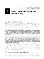
5.2.3 Optional Frequency Hopping
Mobile radio channels suffer from frequency-selective interferences, e.g. frequency-selec-
tive fading due to multipath propagation phenomena. This selective frequency interfer-
ence can increase with the distance from the base station, especially at the cell boundaries
and under unfavorable conditions. Frequency hopping procedures change the transmission
frequencies periodically and thus average the interference over the frequencies in one cell.
This leads to a further improvement of the Signal-to-Noise Ratio (SNR) to a high enough
level for good speech quality, so that conversations with acceptable quality can be
conducted. GSM systems achieve a good speech quality with an SNR of about 11 dB.
With frequency hopping a value of 9 dB is suf®cient. GSM provides for an optional
frequency hopping procedure which changes to a different frequency with each burst;
this is known as slow frequency hopping. The resulting hopping rate is about 217 changes
5 Air Interface ± Physical Layer
68
per second, corresponding to the TDMA frame duration. The frequencies available for
hopping, the hopping assignment, are taken from the cell allocation. The principle is
illustrated in Figure 5.7, showing the time slot allocations for a full-rate TCH. The
exact synchronization is determined by several parameters: the MA, a Mobile Allocation
Index Offset (MAIO), a Hopping Sequence Number (HSN), and the TDMA Frame Number
(FN); see Section 5.3. The use of frequency hopping is an option left to the network
operator, which can be decided on an individual cell basis. Therefore a mobile station
must be able to switch to frequency hopping if a base station notices adverse conditions
and decides to activate frequency hopping.
5.2 Physical Channels
69
Figure 5.7: GSM full-rate traf®c channel with frequency hopping
5.2.4 Summary
A physical GSM channel is de®ned by a sequence of frequencies and a sequence of TDMA
frames. The RFCH sequence is de®ned by the frequency hopping parameters, and the
temporal sequence of time slots of a physical channel is de®ned as a sequence of frame
numbers and the time slot number within the frame. Frequencies for the uplink and down-
link are always assigned as a pair of frequencies with a 45 MHz duplex separation.
As shown above, GSM uses a series of parameters to de®ne a speci®c physical channel of a
base station. Summarizing, these parameters are:
² Mobile Allocation Index Offset (MAIO)
² Hopping Sequence Number (HSN)
² Training Sequence Code (TSC)
² Time Slot Number (TN)
² Mobile Allocation (MA), also known as RFCH Allocation
² Type of logical channel carried on this physical channel
² The number of the logical subchannel (if used) ± Subchannel Number (SCN)
Within a logical channel, there can be several subchannels (e.g. subrate multiplexing of the
same channel type). The TDMA frame sequence can be derived from the type of the
channel and the logical subchannel if present.
5.3 Synchronization
For the successful operation of a mobile radio system, synchronization between mobile
stations and the base station is necessary. Two kinds of synchronization are distinguished:
frequency synchrony and time synchrony of the bits and frames.
Frequency synchronization is necessary so that transmitter and receiver frequencies agree.
The objective is to compensate for tolerances of the less expensive and therefore less stable
oscillators in the mobile stations by obtaining an exact reference from the base station and
to follow it.
Bit and frame synchrony are important in two regards for TDMA systems. First, the
propagation time differences of signals from different mobile stations have to be adjusted,
so that the transmitted bursts are received synchronously with the time slots of the base
station and that bursts in adjacent time slots do not overlap and interfere with each other.
Second, synchrony is needed for the frame structure since there is a higher-level frame
structure superimposed on the TDMA frames for multiplexing logical signaling channels
onto one physical channel. The synchronization procedures de®ned for GSM are explained
in the following section.
5.3.1 Frequency and Clock Synchronization
A GSM base station transmits signals on the frequency carrier of the BCCH which allow a
mobile station to synchronize with the base station. Synchronization means on the one
hand the time-wise synchronization of mobile station and base with regard to bits and
5 Air Interface ± Physical Layer
70
frames, and on the other hand tuning the mobile station to the correct transmitter and
receiver frequencies.
For this purpose, the BTS provides the following signals (Figure 5.6):
² Synchronization Channel (SCH) with extra long Synchronization Bursts (SB), which
facilitate synchronization
² Frequency Correction Channel (FCCH) with Frequency Correction Bursts (FB)
Because of the 0.3-GMSK modulation procedure used in GSM, a data sequence of
logical ``0'' generates a pure sine wave signal, i.e. broadcasting of the FB corresponds
to an unmodulated carrier (frequency channel) with a frequency shift of 1625/24 kHz
(< 67.7 kHz) above the nominal carrier frequency (Figure 5.8). In this way, the mobile
station can keep exactly synchronized by periodically monitoring the FCCH. On the other
hand, if the frequency of the BCCH is still unknown, it can search for the channel with the
highest signal level. This channel is with all likelihood a BCCH channel, because dummy
bursts must be transmitted on all unused time slots in this channel, whereas not all time
slots are always used on other carrier frequencies. Using the FCCH sine wave signal allows
identi®cation of a BCCH and synchronization of a mobile station's oscillator.
For the time synchronization, TDMA frames in GSM are cyclically numbered modulo
2 715 648 ( 26 £ 51 £ 2
11
) with the FN. One cycle generates the so-called hyperframe
structure which comprises 2 715 648 TDMA frames. This long numbering cycle of
TDMA frames is used to synchronize the ciphering algorithm at the air interface (see
Section 6.3). Each base station BTS periodically transmits the Reduced TDMA Frame
Number (RFN) on the SCH. With each SB the mobiles thus receive information about the
number of the current TDMA frame. This enables each mobile station to be time-synchro-
nized with the base station.
The reduced TDMA frame number (RFN) has a length of 19 bits. It consists of three ®elds:
5.3 Synchronization
71
Figure 5.8: Typical power spectrum of a BCCH carrier
T1 (11 bits), T2 (5 bits), and T3
0
(3 bits). These three ®elds are de®ned by (with div
designating integer division):
T1 FN div 26 £ 51 0 2 2047
T2 FN mod 26 0 2 25
T3
0
T3 2 1 div 10 0 2 4
with T3 FN mod 51 0 2 50
The sequences of running values of T2 and T3 are illustrated in Figure 5.9. The value
crucial for the reconstruction of the frame number FN is the difference (T3 2 T2) between
the two ®elds. The time synchronization of a mobile station and its time slots, TDMA
frames, and control channels is based on a set of counters which run continuously, inde-
pendent of mobile or base station transmission. Once these counters have been started and
correctly initialized, the mobile station is in a synchronized state with the base station. The
following four counters are kept for this purpose:
² Quarter Bit Counter counting the Quarter Bit Number (QN)
² Bit Counter counting the Bit Number (BN)
² Time Slot Counter counting the Time Slot Number (TN)
² Frame Counter counting the FN
Because of the bit and frame counting, these counters are of course interrelated, namely in
such a way that the subsequent counter counts the over¯ows of the preceding counter. The
following principle is used (Figure 5.10): QN is incremented every 12/13 ms; BN is
obtained from it by integer division (BN QN div 4). With each transition from 624 to
0 the time slot number TN is incremented, and each over¯ow of TN increments the frame
counter FN by 1.
5 Air Interface ± Physical Layer
72
Figure 5.9: Values T2 and T3 for the calculation of RFN
5.3 Synchronization
73
Figure 5.10: Synchronization timers, simpli®ed: the TDMA frame duration is 156.25 bit times
Figure 5.11: Generation of the GSM frequency hopping sequence
The timers can be reset and restarted when receiving an SB. The Quarter Bit Counter is set
by using the timing of the training sequence of the burst, whereas the TN is reset to 0 with
the end of the burst. The FN can then be calculated from the RFN transmitted on the SCH:
FN 51 £ T3 2 T2mod 261 T3 1 51 £ 26 £ T1
with T3 10 £ T3
0
1 1
It is important to recalculate T3 from T3
0
, although, because of the binary representation,
only the integer part of the division by 10 is taken into account.
If the optional frequency hopping procedure is used (see Section 5.2.3), an additional
mapping of the TDMA frame number onto the frequency to be used is required besides
the evaluation of the synchronization signals from the FCCH and SCH. One has to obtain
the index number of the frequency channel on which the current burst has to be transmitted
from the MA table. This process uses a prede®ned RFNTABLE, the FN, and a HSN; see
Figure 5.11. The MA holds N frequencies, with a maximum value of 64 for N. With this
procedure, every burst is sent on a different frequency in a cyclic way.
5.3.2 Adaptive Frame Synchronization
The mobile station can be anywhere within a cell, which means the distance between
mobile and base station may vary. Thus the signal propagation times between mobile and
base station vary. Due to the mobility of the subscribers, the bursts received at the base
would be offset. The TDMA procedure cannot tolerate such time shifts, since it is based on
the exact synchronization of transmitted and received data bursts. Bursts transmitted by
different mobile stations in adjacent time slots must not overlap when received at the base
by more than the guard period (Figure 5.6), even if the propagation times within the cell are
very different. To avoid such collisions, the start of transmission time from the mobile
station is advanced in proportion to the distance from the base station. The process of
adapting the transmissions from the mobile stations to the TDMA frame is called adaptive
frame alignment.
For this purpose, the parameter Timing Advance (TA) in each SACCH Layer 1 protocol
block is used (Figure 5.18). The mobile station receives from the base station on the
SACCH downlink the TA value it must use; it reports the actually used value on the
SACCH uplink. There are 64 steps for the timing advance which are coded as 0 to 63.
One step corresponds to one bit period. Step 0 means no timing advance, i.e. the frames are
transmitted with a time shift of 3 slots or 468.75 bit durations with regard to the downlink.
At step 63, the timing of the uplink is shifted by 63 bit durations, such that the TDMA
frames are transmitted on the uplink only with a delay of 405.75 bit durations. So the
required adjustment always corresponds to twice the propagation time or is equal to the
round-trip delay (Figure 5.12). In this way, the available range of values allows a compen-
sation over a maximum propagation time of 31.5 bit periods (< 113.3 ms). This corre-
sponds to a maximum distance between mobile and base station of 35 km. A GSM cell may
therefore have a maximum diameter of 70 km. The distance from the base station or the
currently valid TA value for a mobile station is therefore an important handover criterion
in GSM networks (see Section 8.4.3).
5 Air Interface ± Physical Layer
74
The adaptive frame alignment technique is based on continuous measurement of propaga-
tion delays by the base station and corresponding timing advance activity by the mobile
station. In the case of an (unreserved) random access to the RACH, a channel must ®rst be
established. The base station has in this case not yet had the opportunity to measure the
distance of the mobile station and to transmit a corresponding timing advance command. If
a mobile station transmits an access burst in the current time slot, it uses a timing advance
value of 0 or a default value. To minimize collisions with subsequent time slots at the base
station, the access burst AB has to be correspondingly shorter than the time slot duration
(Figure 5.13). This explains the long duration AB of the guard period of 68.25 bit periods,
which can compensate for the propagation delay if a mobile station sends an access burst
from the boundary of a cell of 70 km diameter.
5.4 Mapping of Logical Channels onto Physical Channels
The mapping of logical channels onto physical channels has two components: mapping in
frequency and mapping in time. The mapping of a logical channel onto a physical channel
5.4 Mapping of Logical Channels onto Physical Channels
75
Figure 5.13: Timing for RACH random multiple access
Figure 5.12: Operation of timing advance
in the frequency domain is based on the TDMA frame number (FN), the frequencies
allocated to base and mobile stations ± CA and MA ± and the rules for the optional
frequency hopping (see Section 5.2.3).
In the time domain, logical channels are transported in the corresponding time slots of the
physical channel. They are mapped onto physical channels in certain time-multiplexed
combinations, where they can occupy a complete physical channel or just a part of a
physical channel. Whereas user payload data is allocated a dedicated full-rate or half-
rate channel, logical signaling (control) channels have to share a physical channel.
The logical channels are organized by the de®nition of complex superstructures on top of
the TDMA frames, forming so-called multiframes, superframes and hyperframes (Figure
5.14). For the mapping of logical onto physical channels, we are interested in the multi-
frame domain. These multiframes allow us to map (logical) subchannels onto physical
channels. Two kinds of multiframes are de®ned (Figure 5.15): a multiframe consisting of
26 TDMA frames (predominantly payload ± speech and data ± frames) and a multiframe of
51 TDMA frames (predominantly signaling frames).
Each hyperframe is divided into 2048 superframes. With its long cycle period of 3 h
28 min 53.760 s, it is used for the synchronization of user data encryption. A superframe
consists of 1326 consecutive TDMA frames which therefore lasts for 6.12 s, like 51
multiframes of 26 TDMA frames or 26 multiframes of 51 TDMA frames. These multi-
frames are again used to multiplex the different logical channels onto a physical channel as
shown below.
5 Air Interface ± Physical Layer
76
Figure 5.14: GSM frame structures
Figure 5.15: GSM multiframes
5.4.1 26-Frame Multiframe
Each 26 subsequent TDMA frames form a multiframe which multiplexes two logical
channels, a TCH and the SACCH, onto the physical channel (Figure 5.16). This process
uses only one time slot per TDMA frame for the corresponding multiframe (e.g. time slot 3
in Figure 5.15), since a physical channel consists of just one time slot per TDMA frame.
Besides the 24 TCH frames for user data, this multiframe also contains an AC frame for
signaling data (SACCH data). One frame (the 26th) remains unused in the case of a full-
rate TCH (IDLE/AC); it is reserved for the introduction of two half-rate TCHs; then the
26th frame will be used to carry the SACCH channels of the other half.
The data of the Fast Associated Control Channel (FACCH) is transmitted by occupying
one half of the bits in eight consecutive bursts, by ``stealing'' these bits from the TCH. For
this purpose, the Stealing Flags of the normal bursts are set (Figure 5.6).
A subscriber has available a gross data rate of 271 kbit/s 4 8 33.9 kbit/s (Section 5.2). Of
this budget, 9.2 kbit/s are for signaling, synchronization, and guard periods of the burst. Of
the remaining 24.7 kbit/s, in the case of the 26-frame multiframe, 22.8 kbit/s are left for the
coded and enciphered user data of a full-rate channel, and 1.9 kbit/s remain for the SACCH
and IDLE.
5.4.2 51-Frame Multiframe
For the transmission of the control channels which are not associated with a TCH (all
except FACCH and SACCH), a multiframe is formed consisting of 51 consecutive TDMA
frames (Figure 5.6). According to channel con®guration (Section 5.1), the multiframe is
used differently. In each case, multiframes of 51 TDMA frames serve the purpose of
mapping several logical channels onto a physical channel.
Furthermore, some of these control channels are unidirectional, which results in different
structures for uplink and downlink. For some con®gurations, two adjacent multiframes are
required to map all the logical channels. Some examples are illustrated in Figure 5.17.
They correspond to the combinations B2, B3, and B4 in Table 5.3 whereas for channels
SDCCH and SACCH some 4 or 8 logical subchannels have been de®ned (D0, D1, ¼, A0,
A1, ¼). One of the frequency channels of the CA of a base station is used to broadcast
synchronization data (FCCH and SCH) and the BCCH. Since the base station has to
transmit in each time slot of the BCCH carrier to enable a continuous measurement of
the BCCH carrier by the mobile station, a Dummy Burst (DB) is transmitted in all time
slots with no traf®c.
On time slot 0 of the BCCH carrier, only two combinations of logical channels may be
transmitted, the combinations B2 or B3 from Table 5.3: (BCCH 1 CCCH 1 FCCH 1
5.4 Mapping of Logical Channels onto Physical Channels
77
Figure 5.16: Channel organization in a 26-frame multiframe
SCH 1 SDCCH 1 SACCH or BCCH 1 CCCH 1 FCCH 1 SCH). No other time slot of
the CA must carry this combination of logical channels.
As one can see in Figure 5.17, in the time slot 0 of the BCCH carrier of a base station
(downlink) the frames 1, 11, 21,¼ are FCCH frames, and the subsequent frames 2, 12,
22,¼ form SCH frames. Frames 3, 4, 5, 6 of the 51-frame BCCH multiframe transport the
5 Air Interface ± Physical Layer
78
Figure 5.17: Channel organization in a 51-frame multiframe
appropriate BCCH information, whereas the remaining frames may contain different
combinations of logical channels. Once the mobile station has synchronized by using
the information from FCCH and SCH, it can determine from the information in the
FCCH and SCCH how the remainder of the BCCH is constructed. For this purpose, the
base station Radio Resource Management periodically transmits a set of messages to all
mobile stations in this cell.
These System Information Messages comprise six types, of which only Types 1±4 are of
interest here. Using the TDMA frame number (FN), one can determine which type is to be
sent in the current time slot by calculating a Type Code (TC):
TC FN div 51 mod 8
Table 5.5 shows how the TC determines the type of the system information message to be
sent within the current multiframe.
Of the parameters contained in such a message, the following are of special interest:
BS_CC_CHANS determines the number of physical channels which support a CCCH.
The ®rst CCCH is transmitted in time slot 0, the second one in time slot 2, the third one in
time slot 4, and the fourth one in time slot 6 of the BCCH carrier. Another parameter,
BS_CCCH_SDCCH_COMB, determines whether the DCCHs SDCCH(0±3) and
SACCH(0±3) are transmitted together with the CCCH on the same physical channel. In
this case, each of these dedicated control channels consists of four subchannels.
Each of the CCCHs of a base station is assigned a group CCCH_GROUP of mobile
stations. Mobile stations are allowed random access (RACH) or receive paging informa-
tion (PCH) only on the CCCH assigned to this group. Furthermore, a mobile station needs
only to listen for paging information on every Nth block of the Paging Channel (PCH).
The number N is determined by multiplying the number of paging blocks per 51-frame
multiframe of a CCCH with the parameter BS_PA_MFRMS designating the number of
multiframes between paging frames of the same Paging Group (PAGING_GROUP).
Especially in cells with high traf®c, the CCCH and paging groups serve to subdivide traf®c
and to reduce the load on the individual CCCHs. For this purpose, there is a simple
algorithm which allows each mobile station to calculate its respective CCCH_GROUP
5.4 Mapping of Logical Channels onto Physical Channels
79
Table 5.5: Mapping of frame number onto BCCH message
TC System information
message
0 Type 1
1 Type 2
2, 6 Type 3
3, 7 Type 4
4, 5 Any (optional)
and PAGING_GROUP from its IMSI and parameters BS_CC_CHANS, BS_PA_MFRMS
and N.
5.5 Radio Subsystem Link Control
The radio interface is characterized by another set of functions of which only the most
important ones are discussed in the following. One of these functions is the control of the
radio link: Radio Subsystem Link Control, with the main activities of received-signal
quality measurement (quality monitoring) for cell selection and handover preparation,
and of transmitter power control.
If there is no active connection, i.e. if the mobile station is at rest, the BSS has no tasks to
perform. The MS, however, is still committed to continuously observing the BCCH carrier
of the current and neighboring cells, so that it would be able to select the cell in which it
can communicate with the highest probability. If a new cell needs to be selected, a Loca-
tion Update may become necessary.
During a connection (TCH or SDCCH), the functions of channel measurement and power
control serve to maintain and optimize the radio channel; this also includes adaptive frame
alignment (Section 5.3.1) and frequency hopping (Section 5.2.3). Both need to be done
until the current base can hand over the current connection to the next base station.
These link control functions are performed over the SACCH channel. Two ®elds are
de®ned in an SACCH block (Figure 5.18) for this purpose, the power level and the TA.
On the downlink, these ®elds contain values as assigned by the BSS. On the uplink, the MS
inserts its currently used values. The quality monitoring measurement values are trans-
mitted in the data part of the SACCH block.
The following illustrates the basic operation of the Radio Subsystem Link Control at the
BSS side for an existing connection; the detailed explanation of the respective functions is
given later. In principle, the radio link control can be subdivided into three tasks: measure-
ment collection and processing, transmitter power control, and handover control.
5 Air Interface ± Physical Layer
80
Figure 5.18: SACCH block format
In the example of Figure 5.19, the process BSS_Link_Control starts at initialization the
processes BSS_Power_Control and BSS_HO_Control and then enters a measurement
loop, which is only left when the connection is terminated. In this loop, measurement
data is periodically received (every 480 ms) and current mean values are calculated. At
®rst, these measurement data are supplied to the transmitter power control to adapt the
power of MS and BSS to a new situation if necessary. Thereafter, the measurement data
and the result of the power control activity are supplied to the handover process, which can
then decide whether a handover is necessary or not.
5.5 Radio Subsystem Link Control
81
Figure 5.19: Principal operation of the radio subsystem link control