Tài liệu Pracrical Machinery Management for Process Plants P2 ppt
Bạn đang xem bản rút gọn của tài liệu. Xem và tải ngay bản đầy đủ của tài liệu tại đây (231.36 KB, 10 trang )
26
Major
Process
Equipment Maintenance
and
Repair
If
failed bearings are suspected in pump or motor:
Check radial clearance and end float in motor.
Run motor and check for abnormal noise, vibration.
If motor is bad, remove and repair.
Diagnosing Pump and
Seal
Problems In the Shop
While the pump is being repaired it is advisable to carefully examine
every component.
A
recommended procedure
is
to
match mark all parts
prior to disassembly and
to
make the following checks while dismantling
the pump:
1.
Visually check impeller and nut for wear, erosion, corrosion and
2.
Remove seal flange nuts and check seal tension.
3.
Record impeller position
in
relation
to
pump frame.
4.
Remove impeller nut and impeller.
5.
Jnspect wear rings inboard, if any.
6.
Check and record throttle bushing clearance.
7.
Check body gasket faces.
8.
Remove stuffing box body from pump frame.
9.
Check stuffing
box
gasket face, bore, and pilots.
other deterioration.
10.
Remove and inspect all shaft keys.
11.
Remove sleeve,
seal,
sleeve gasket and sleeve flange. If neces-
sary, determine the cause of seal failure and inspect condition
of
parts.
12.
Check pump bearings for roughness. Record
shaft
end float,
check shaft for wear, erosion, corrosion and straightness.
13.
Excessive shaft axial end play:
Excessive shaft movement can result in pitting, fretting,
or
wear at
points of contact in shaft packing and mechanical seal areas.
It
can
cause over or under-loading on springs resulting
in
high
wear
rates
and leakage.
It
can also cause excessive strain and
wear
on pump
bearings. Defective bearings in turn can cause excessive shaft end
To
check for this condition a dial indicator should be installed
so
that
its stem bears against the shoulder on the
shaft
(Figure
1-6).
Play.
Installatiori,
Maintenance, and Repair
of
Horizontal
Pumps
27
RADIAL BEARING
THRUST
BEARING
RADIAL BEARING
Figure
1-6.
Checking
for
end
play.
Figure
1-7.
Checking
for
bent
shaft.
A
soft
hammer should be used to lightly tap the shaft
on
one end
and then the other. Total indicated end play should be between
.001
in.
and .004 in. for proper assembly.
14. Bent shaft:
When a pump shaft
is
bent or out of alignment, bearing life, seal
life,
and
performance
are
impaired. Bent shafts also cause vibra-
tion and coupling failures.
To
check for this condition, install
a
dial
indicator to the pump housing
and
adjust
so
that the stem bears
on
shaft outside diameter. Rotate shaft and check for
run-out.
If
run-out
is
greater than
.002
in.
the
shaft should be straightened
(Figure
1-7).
The shaft should be checked in several different locations.
15. Check all pilot fits for concentricity. Also check for excessive
shaft radial movement:
Excessive radial shaft movement allows shaft and seal to whip,
deflect, and vibrate. This type of movement
is caused by improper
bearing fit in pump bearing housings
or
possibly an undersized
shaft. If the bearing bore is oversized, determine if it was caused
by corrosion, wear or improper machining.
To
check for this con-
dition, a dial indicator should be placed
on
the shaft OD as close to
the bearings as possible. The shaft should be lifted,
or
light pres-
sure applied to shaft. If the total movement exceeds
.003
in.
maxi-
mum, bearings and bearing fits should be checked and necessary
repairs made (Figure
1-8).
28
Major Process Equipment Maintenance and Repair
RADIAL BEARING
RADIAL BEARING
T
Figure
1-8.
Checking for whip
or
deflection.
Figure
1-9.
Checking for stuffing
box
squareness.
16.
Stuffing box squareness:
If
the face of the pump stuffing box is not perpendicular to the
shaft axis, the mechanical seal gland will tilt when installed. This
may cause the seal to wobble and could lead to seal failure.
To check for this condition, clamp a dial indicator to the shaft with
the stem against the face of the stuffing box, after the cover has
been bolted in place. Total indicator measurement should not ex-
ceed
.002
in.
If
face measurement should exceed this tolerance,
the cover should be placed in a lathe and machined square. Stuff-
ing box faces should always be checked for pitting, nicks, burrs,
and possible erosion before installing the seal (Figure
1-9).
17.
Check for bore concentricity:
The concentricity of a stuffing box bore and shaft can be difficult
to measure because of rust or corrosion due to leaking gaskets.
Concentricity is critical and may have to be reestablished by weld-
ing and remachining. On large double-ended pumps where there is
a large separation between stuffing boxes it is very important that
the concentricity
be
held to design tolerances.
To
check for concentricity, attach a dial indicator to the shaft and
sweep as shown in Figure
1-10.
Stuffing boxes should be concentric to the shaft axis within
.005
in. total indicator reading. If readings are in excess of this, the
pump may have to be realigned and redowelled.
Installation, Maintenance,
and
Repair
of
Horizontal
Pumps
29
"U
Figure
1-1
0.
Checking
for
bore
concentricity.
18.
If
bearings are found to be rough or the end float
is
excessive:
Remove pump shaft and bearing from housing.
Remove bearings from shaft.
Check shaft fits, coupling, bearings.
Check shaft straightness and polish lightly.
Clean and check bearing fits in housing.
Repair or replace all faulty and worn parts prior to reassembly.
Detailed Inspection Procedures
There
are
several basic rules that should
be
observed when inspecting
and
repairing process pumps.
Some
of
these
are:
1.
Have
a
good understanding what clearances and fits should
be
met.
2.
Record all data and measurements on suitable inspection
forms.
(See Appendixes A and
B
at the end of this Chapter.) Record all
unusual deterioration found while dismantling the pump.
3.
Use
new gaskets and O-rings when reassembling the pump.
4.
Keep the work place clean.
Inspection
of
Parts
Shafts
1.
Check for straightness: Runout
is
not
to
exceed .002 in. Bearing
2.
Inspect threads, keyways, and shoulders on shaft. Repair if dam-
seats must be
in
good
condition.
aged.
30
Major Process
Equipment
Maintenance and Repair
3.
Measure and record all shaft fits. Undersized or damaged fits
should be repaired by the procedures outlined in Volume
3
of this
series.
Case End Wall and Cover
1.
Measure and record all fits between pump casing and mating parts.
2. Remove all plugs and fittings to inspect threads. Reinstall all plugs
3.
Inspect and indicate mounting pads to ensure they are flat and par-
and fittings.
allel with pump centerline. Machine, if out of alignment.
Bearing Housing and Bearings
1.
Observe good anti-friction bearing mounting procedures (see Vol-
ume
3
for details).
2. Ball bearings: Replace if worn, loose, or rough and noisy when ro-
tated. If dirty, clean with solvent, dry and coat with a good lubri-
cant. New bearings should not be unwrapped until ready for use.
Whenever in doubt about the condition of a bearing, scrap it. But if
the bearing
is
still relatively new, and feels and looks good, don’t
discard it.
3.
Sleeve bearings: Check surfaces of bearing and
shaft
for imperfec-
tion, babbitt build-up, and hot spots. Small imperfections do not
harm the bearing.
A
typical diametral clearance is
.0015
in. per in.
of shaft diameter. For proper operation, clearances should never ex-
ceed
.003
in. per in. of shaft diameter on typical pumps.
Mechanical Seals
Refer to Chapter
8
in Volume
3
for maintenance and repair of mechani-
cal seals.
Impellers
1.
Replace if excessively worn or corroded. The impeller should have
been statically and dynamically balanced at the factory, and static
and dynamic balance must be maintained for proper operation of
your equipment.
2. Inspect and measure impeller bore and if worn or deteriorated, ma-
chine true. Recondition the shaft to fit revised impeller bore size.
Refer to Volume
3
for guidance.
3.
Measure outside diameter of impeller wear rings and record size.
Refer to Table 1-2 for diametral clearances.
Installation, Maintenance,
and
Repair
of
Horizontal
Pumps
31
Table
1-2
Required Diametral Clearances-Process Pumps Wear Rlngs’
Diametral Clearance
Wear Ring Diameter Under
500°F
Over
500°F
3112
in.
through
5
in.
,016
.018
5
in.
through
6
in.
.017
.019
7
in. throueh
8
in. .019
.02
1
6
in. through 7 in.
.018
,020
8
in.
through 9 in.
.020
.022
9
in. through
10
in.
.02
1
.023
10
in.
through
11
in.
.022
.024
11
in. and over
,023
.025
*
An
additional diametral clearance
of.
005
in.
is provided ifboth wear
rings
are made
of
austenitic stainless
steel,
Monel or other materials with high galling tendencies.
Casing and impeller wear rings are provided at both sides of the impel-
ler on API-type pumps. These rings allow
a
small clearance to be main-
tained between the rotating impeller and stationary casing rings. For
proper hydraulic performance these clearances should approximate the
experience values indicated
in
Table
1-2.
Rings should
be
replaced when
clearances have increased to a point where hydraulic requirements cannot
be met or where inefficient operation would prove wasteful. For API val-
ues refer to Table
1-3.
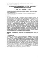
Why do wear ring clearances deserve our attention? The following sec-
tion will provide the answer.
Keep Pumps Operatlno Efficiently*
*
In
centrifugal pumps, it
is
essential to pump operability and hydraulic
performance that excessive internal leakage
(or
recirculation) be pre-
vented. This
is
accomplished by establishing and maintaining
close
run-
ning clearances been stationary and rotating wear rings which restrict
fluid flow to
seal
between
the
inlet and outlet
of
each impeller
and
be-
tween stationary and rotating interstage bushings. These bushings
effect
sealing between the stages of
a
multistage pump. Certain types of pumps
contain hydraulic thrust balancing devices, another source
of internal
pump leakage.
**
From
“Keep
Pumps Operating Efficiently,”
by
J.
Lightle and
J.
Hohman,
Dresser
Industries, Pacific Pump Division, in
Hydrocarbon Processing,
Sept. 1979. By
per-
mission of Dresser Industries, Pacific Pump Division.
32
Major Process Equipment Maintenance and Repair
As
the close clearances become larger through wear, corrosion, ero-
sion or perhaps questionable maintenance practices, internal leakage
rates increase. The increased leakage must be pumped and repumped
continuously by the impeller, requiring additional input horsepower.
The amount
of
added power to continuously recirculate excessive in-
ternal leakage is a function
of the pump specific speed*. In low specific
speed
pumps (low capacity-high head) excessive running clearances re-
sult in larger percentage changes in power requirements than occur in
high specific
speed
pumps (high capacity-low head). This
is
reflected in
the empirical data plotted in Figure
1-1
1.
*
For
an
explanation
of
pump specific
speed
refer to Figure
1-13.
35
u)
c
30
E
P
P
&
25
3
n
n
2
0-
0
5
E
20
E
C
P
15
P)
0
m
C
c.
8
&
10
n
C
/
/
S
0
0
20 40 60 80 100 120 140 160 180 200
/
/
/is-
/
Percentage increase in wear ring clearance
Figure
1-1 1.
Added power resulting from excessive wear ring clearance for different
cific speeds.
spe-
Installation, Maintenance, and Repair
of
Horizontal Pumps
33
140
6
130-
D
f
110-
U
-
120-
0
2100-
9
F
80-
i
90
70-
-
c
'g
U
:
a
1w
90
120
BO
c
110
70
'f
n
1w
60%
90
50
a.
40
.I
7
c
e4
70
30
YI
80
Ni
50 10
40
0
Capacity
-%
of
design
Figure
1-12.
Pump performance curves.
The data in Figure 1-1 1 are somewhat misleading since it may be easy
to
conclude that high specific speed pumps do not cause excessive costs
resulting from worn clearances. Beware, however, that small percentage
changes of large horsepowers result in large annual costs. Also, as noted
in the following example, mechanical operation may be adversely af-
fected by excessive clearances in pumps of various specific speed ranges.
A
typical example:
Consider a single stage, overhung process pump-one
designed to produce a total head of 725
ft
at 1,550 gpm when operating at
3,550 rpm. Such a unit can be considered a typical process pump. Figure
1-12 shows the characteristic performance curves for an example pump;
all scales are shown as
a
percentage of the design conditions. The solid
curves indicate performance of the pump in new condition.
At the design operating capacity, the unit is 67 percent efficient, re-
quiring
424
bhp* input horsepower (assuming the pumpage has a specific
gravity of
1
.O).
Referring to the specific speed nomogram (Figure 1-13), it is deter-
mined that our example pump has
a
specific speed of
1,OOO.
Now, going back to Figure 1-1 1, we
see
that if the wear rings have
worn to the point where running clearances have doubled (increased by
100 percent), a pump having
a
specific speed of
1,OOO
will suffer an in-
*
Brake
horsepower
34
Major Process Equipment Maintenance
and
Repair
Figure
1-13.
Specific speed
nomogram.
crease in required horsepower input
of
approximately 4.8 percent; in our
example, this amounts to approximately
20
brake horsepower. The
.038
in. wear performance curve on Figure 1-12 shows the worn-condition
performance characteristics
of
the example pump.
Figure 1-14 shows the annual power cost this extra 20 brake horse-
power will represent to you, based on
300
days per year operation.
If
your power cost is
6C/kWh,
your annual power cost resulting from
internal wear in this pump would be
$6,440.
If yours is a cctypical”
100,OOO
bbl/day refinery using
25,000
pump horsepower, an overall in-
crease of
5
percent in
your
pump horsepower requirements could repre-
sent additional costs
of
WO0,OOO
per year.
Maintenance practices.
Normal
operational wear is not the only cause of
excessive part clearances in pumps, nor are wasted dollars and fuel the
only adverse effects.
Intentional opening up
of
wear ring or other wearing part clearances is
used by some maintenance people
to
solve certain pump operating prob-
lems. Unfortunately, such practices sometimes appear to be effective-
over the short run. Over a period
of
time, however, such practices can
create other problems. The resulting increased internal leakages within
Installation, Maintenance, and Repair
of
Horizontal Pumps
35
the pump (and the accompanying increased power required to pump the
additional flow) seem to many to be a small price to pay, if in fact such
criteria are considered at all. But, from a purely mechanical standpoint,
the stability of the rotor is perhaps safeguarded only as long as normal
running clearances are maintained. Typical consequences of liberally
open clearances are likely to include excessive vibration, overheating and
ultimately pump or driver bearing failure, shaft breakage, driver over-
loading, and possible total pump destruction. Ultimate maintenance costs
can be very high and unit operation can be compromised through prema-
ture and repeated outages.
If
two or more pumps are designed for parallel operation and share to-
tal
capacity, then unequal running clearances can cause unequal load
sharing by the pumps. One or more of the units can be forced to operate
at significantly more or less than its design flow rate. Efficiency falls
off
and brake horsepower requirements increase even beyond those caused
by excessive running clearances.
Running clearances.
Greater than normal wear ring clearances at the im-
peller inlet eye increase the flow rate through the impeller (not out the
discharge nozzle of the pump)
,
increase the effective inlet fluid tempera-
Increased
power
consumption,
bhp
Figure
1-14.
Annual costs based on
300
days per year continuous operation.