Tài liệu SIMATIC COM PROFIBUS doc
Bạn đang xem bản rút gọn của tài liệu. Xem và tải ngay bản đầy đủ của tài liệu tại đây (969.84 KB, 111 trang )
………… o0o…………
SIMATIC COM PROFIBUS
6,(0(16
Important information,
Contents
Product overview
1
Installation and uninstallation
2
User interface
3
PROFIBUS-DP
configuration example
4
PROFIBUS-FMS
configuration example
5
Running PROFIBUS-DP and
PROFIBUS-FMS in parallel
6
Importing configurations
7
Exporting configurations
8
Device master files
9
Assigning shared input
masters
10
Taking into account other
masters that are not contained
in COM PROFIBUS
11
Tips and tricks
12
Glossary, Index
SIMATIC
COM PROFIBUS
Manual
This manual is part of the
COM PROFIBUS CD-ROM
(order no. (66()
EWA 4NEB 780 6035-02
Edition 1
Safety Guidelines
This manual contains notices which you should observe to ensure your own personal safety, as well as
to protect the product and connected equipment. These notices are highlighted in the manual by a war-
ning triangle and are marked as follows according to the level of danger:
!
'DQJHU
indicates that death, severe personal injury or substantial property damage ZLOO result if proper pre-
cautions are not taken.
!
:DUQLQJ
indicates that death, severe personal injury or substantial property damage FDQ result if proper pre-
cautions are not taken.
!
&DXWLRQ
indicates that minor personal injury or property damage can result if proper precautions are not taken.
1RWH
draws your attention to particularly important information on the product, handling the product, or to a
particular part of the documentation.
Qualified Personnel
Only TXDOLILHGSHUVRQQHO should be allowed to install and work on this equipment. Qualified persons
are defined as persons who are authorized to commission, to ground, and to tag circuits, equipment,
and systems in accordance with established safety practices and standards.
Correct Usage
Note the following:
!
:DUQLQJ
This device and its components may only be used for the applications described in the catalog or the
technical description, and only in connection with devices or components from other manufacturers
which have been approved or recommended by Siemens.
This product can only function correctly and safely if it is transported, stored, set up, and installed
correctly, and operated and maintained as recommended.
Trademark
SIMATIC®, SIMATIC HMI® and SIMATIC NET® are registered trademarks of SIEMENS AG.
Third parties using for their own purposes any other names in this document which refer to trade-marks
might infringe upon the rights of the trademark owners.
Copyright © Siemens AG 1999 All rights reserved
The reproduction, transmission or use of this document or ist
contents is not permitted without express written authority. Offen-
ders will be liable for damages. All rights, including rights created
by patent grant or registration of a utility model or design, are
reserved.
Siemens AG
Automation Group
Industrial Automation Systems
P.O. Box 4848, D-90327 Nuremberg
Disclaimer of Liability
We have checked the contents of this manual for agreement with
the hardware and software described. Since deviations cannot be
pre-cluded entirely, we cannot guarantee full agreement. However,
the data in this manual are reviewed regularly and any necessary
corrections included in subsequent editions. Suggestions for im-
provement are welcomed.
©Siemens AG 1999
Technical data subject to change.
Siemens Aktiengesellschaft
COM PROFIBUS
EWA 4NEB 780 6035-02
iii
,PSRUWDQWLQIRUPDWLRQ
3XUSRVHRIWKHPDQXDO
The information in this manual tells you how to install COM PROFIBUS and carry
out complete configurations with COM PROFIBUS.
We use two full configuration examples to illustrate how to work with
COM PROFIBUS. These contain all the important functions of COM PROFIBUS
and can be easily followed:
•
PROFIBUS-DP configuration example
•
PROFIBUS-FMS configuration example
7DUJHWDXGLHQFH
This manual is aimed at those who use COM PROFIBUS for planning,
commissioning and diagnostics with PROFIBUS-DP and PROFIBUS-FMS bus
systems based on the EN 50170, Volume 2, PROFIBUS standard.
You will find product-specific configuration information on your PROFIBUS devices
in the product documentation.
6FRSHRIYDOLGLW\
This manual is valid for &20352),%86DVRI9.
It contains a description of the product’s functions that was correct at the time of
going to press. We reserve the right to describe new functions or changes in an
accompanying product information document.
2QOLQHKHOSV\VWHP
All the information you will need is offered in an online help system in
COM PROFIBUS. This contains full descriptions of all the functions of COM
PROFIBUS. In addition, you can also request context-sensitive information on any
open dialog box.
Important information
COM PROFIBUS
iv EWA 4NEB 780 6035-02
$LGVWRDFFHVVLQJLQIRUPDWLRQ
In order to facilitate rapid access to specific information, the manual contains the
following aids:
•
A complete table of contents at the beginning of the manual
•
A glossary after the appendices, in which important technical terms used in the
manual are defined
•
A thorough index at the end of the manual, which quickly enables you to find
the information you require
)XUWKHUVXSSRUW
If you have any questions of a technical nature, please get in touch with your
contact at the Siemens representative or office assigned to you. You will find the
address in the manuals for the Siemens DP masters - for example, in the "Siemens
Worldwide" appendix of the manual S7-300 Programmable Controller; Hardware
and Installation, in catalogs and on CompuServe (GO AUTFORUM).
If you require device master files, you can obtain them as follows:
•
By direct modem link on +49 (911) 737972
•
On the Internet at />&RQVWDQWO\XSGDWHGLQIRUPDWLRQ
You can obtain constantly updated information on SIMATIC products:
• On the Internet at />• By calling the fax polling number +49 8765-93 00 50 00
In addition, SIMATIC Customer Support provides you with current information and
downloads that can be of use to you with your SIMATIC products:
• On the Internet at />• At the SIMATIC Customer Support Mailbox on +49 (911) 895-7100
To access the mailbox, use a V.34 (28.8 kbps) modem and set the following
parameters: 8, N, 1, ANSI. Alternatively, use ISDN (x.75, 64 kbps).
You can contact SIMATIC Customer Support by phone on +49 (911) 895-7000 and
by fax on +49 (911) 895-7002. You can also send inquiries by e-mail on the
Internet or to the above mailbox.
COM PROFIBUS
EWA 4NEB 780 6035-02
v
&RQWHQWV
,PSRUWDQWLQIRUPDWLRQ LLL
&RQWHQWV Y
3URGXFWRYHUYLHZ
,QVWDOODWLRQDQGXQLQVWDOODWLRQ
8VHULQWHUIDFH
352),%86'3FRQILJXUDWLRQH[DPSOH
4.1 Starting configuration 20
4.2 Setting up the bus configuration 21
4.3 Entering bus parameters 22
4.4 Entering master parameters 24
4.5 Entering host parameters 26
4.6 Entering slave parameters for the ET 200B 27
4.7 Entering slave parameters for the ET 200M 31
4.8 Entering slave parameters for the ET 200S 36
4.9 Entering slave parameters for the IM 308-C DP slave 42
4.10 Assigning groups 46
4.11 Saving the configuration 47
4.12 Documenting and printing the configuration 47
4.13 Commissioning the programming device/PC online on the bus 48
4.14 Transferring (exporting) the configuration to the DP master 49
4.15 Assigning a PROFIBUS address 51
4.16 Testing the signal states of the individual DP slaves 52
4.17 Commissioning the bus configuration 53
4.18 Evaluating a diagnosis with COM PROFIBUS 54
352),%86)06FRQILJXUDWLRQH[DPSOH
5.1 Starting configuration 58
5.2 Setting up the bus configuration 59
5.3 Entering bus parameters 60
5.4 Entering master parameters 62
5.5 Entering station parameters for the S7-300 CP 343-5 FMS 65
Contents
COM PROFIBUS
vi EWA 4NEB 780 6035-02
5.6 Setting FMS connections to the S7-300 CP 343-5 FMS 65
5.7 Entering station parameters for the ET 200U DP/FMS 72
5.8 Setting FMS connections to the ET 200U DP/FMS 73
5.9 Saving the configuration 78
5.10 Documenting and printing the configuration 78
5.11 Transferring (exporting) the configuration to an NCM file 79
5XQLQJ352),%86'3DQG352),%86)06LQSDUDOOHO
,PSRUWLQJFRQILJXUDWLRQV
([SRUWLQJFRQILJXUDWLRQV
'HYLFHPDVWHUILOHV
$VVLJQLQJVKDUHGLQSXWPDVWHUV
7DNLQJLQWRDFFRXQWRWKHUPDVWHUVWKDWDUHQRWFRQWDLQHGLQ&20352),%86
7LSVDQGWULFNV
*ORVVDU\ *ORVVDU\
,QGH[ ,QGH[
COM PROFIBUS
EWA 4NEB 780 6035-02
7
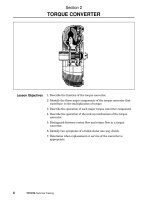
3URGXFWRYHUYLHZ
:KDWLV&20352),%86"
The COM PROFIBUS configuration software makes it easy to configure and
commission PROFIBUS-DP and PROFIBUS-FMS bus systems.
COM PROFIBUS runs under MS Windows 9x/NT and offers you a graphical user
interface that allows you to:
•
Configure masters and slaves easily
•
Set transmission rates for the PROFIBUS bus system
•
Transfer (export) the data directly to the master via the PROFIBUS bus system
•
Commission the PROFIBUS bus system with the aid of diagnostic functions
•
Display the status of inputs and outputs and set defined outputs
• Document the configuration in detail
&RQILJXUDWLRQZLWK&20352),%86
COM PROFIBUS is installed on the programming device/PC.
COM
PROFIBUS
Programming
device / PC
Memory
card
IM 308-C:
S5-115U
S5-135U
S5-155U
NCM
file
SIMATIC
NET PC
module
Export via
PROFIBUS
DP
master
Figure 1-1 Configuration with COM PROFIBUS
Product overview
COM PROFIBUS
8 EWA 4NEB 780 6035-02
&RQILJXUDEOH'3PDVWHUV
•
The S5-115U, S5-135U or S5-155U with the IM 308-C as a DP master (up to
12 Mbps)
•
The S5-95U with a DP master interface (up to 1.5 Mbps)
•
The SIMATIC NET PC module CP 5412 (A2) as a DP master
•
Communication modules for connecting the SIMADYN D control system
•
The TELEPERM M programmable controllers AS 388 TM/488 TM
•
The SIMATIC TI505-FIM field interface module for connecting the
SIMATIC TI505
•
The PROFIBUS-DP IM 180 master interface module
•
The SIMATIC NET PC modules CP 5511, CP 5611, CP 5611 Onboard (in the
PG 7x0 PII) and CP 5411 as DP masters
&RQILJXUDEOH'3VODYHV
•
ET 200 distributed I/O devices: the ET 200B, ET 200C, ET 200L, ET 200M,
ET 200S and ET 200X (up to 12 Mbps) and the ET 200U, ET 200L (up to 1.5
Mbps)
• The S5-115U, S5-135U or S5-155U with the IM 308-C as a DP slave (up to 12
Mbps)
• The S5-95U with a DP slave interface (up to 1.5 Mbps)
• DP/AS-I Link as the interface to the actuator/sensor interface
• The S7-200 with the CPU 215-2 DP or CP 242-8 as a DP slave
• The S7-300 with the CPU 315-2 DP or CP 342-5 as a DP slave
• The S7-400 with the CP 443-5 as a DP slave
• Communication modules for connecting:
• SIMOVERT master drives
• SIMOREG converters
• The SIMADYN D control system
• SIMOCODE-DP low-voltage switchgear
• Text displays and operator panels for machine-oriented operation/monitoring
• MOBY identification systems
• The SIMODRIVE sensor - absolute value sensor with PROFIBUS-DP
connection
• SIPOS electric actuators
• SIPART industrial/process controllers
• The PROFIBUS-DP RBC interface module for connecting the SIMATIC TI505
Product overview
COM PROFIBUS
EWA 4NEB 780 6035-02
9
&RQILJXUDEOH)06PDVWHUV
•
The SIMATIC NET PC module CP 5412 (A2) as an FMS master
&RQILJXUDEOH)06VWDWLRQV
•
The ET 200U DP/FMS distributed I/O device
•
SIMOCODE FMS low-voltage switchgear
•
The SIMATIC NET PC module CP 5412 (A2) as an FMS station
•
The CP 5431 FMS communication processor
•
The S7-300 with the CP 343-5 as an FMS station
•
The S7-400 with the CP 443-5 as an FMS station
)LHOGGHYLFHVRIRWKHUYHQGRUV
COM PROFIBUS also allows you to parameterize the field devices of other
vendors. Device master files are generally supplied with the field devices. These
can be integrated in configuration tools and permit easy and user-friendly
parameterization. COM PROFIBUS can interpret these device master files
provided the files are created in accordance with the EN 50170, Volume 2,
PROFIBUS standard.
&RQILJXULQJ(7GHYLFHVIRU'3PDVWHUVRIRWKHUYHQGRUV
When ET 200 devices are connected to DP masters that are not parameterized
with COM PROFIBUS (DP masters of other vendors), a device master file with
predefined settings can be created with COM PROFIBUS in accordance with the
EN 50170, Volume 2, PROFIBUS standard.
This device master file is then loaded in the other vendor’s configuration software
and can be used to parameterize the ET 200 device with ease. The user-friendly
plain-text parameterization of COM PROFIBUS is used. Hexadecimal code entries
in the configuration software of the other vendor are not required.
'HYLFHPDVWHUILOHVIRU&20352),%86
A device master file is required for every PROFIBUS device configured with
COM PROFIBUS.
Device master files for the above PROFIBUS devices (DP and FMS) are supplied
with COM PROFIBUS. The device master files of new Siemens I/O devices whose
device master files are not in COM PROFIBUS’s GSD directory are available from
the interface center. You can download them by modem on:
• Tel. +49 (911) 737972
• Tel. +49 (911) 730983
Product overview
COM PROFIBUS
10 EWA 4NEB 780 6035-02
Alternatively, you can download the device master files for SIEMENS devices on
the Internet. You will find all the device master files under "Downloads" on the
SIMATIC Customer Support Web page at /> 2QOLQHKHOSV\VWHP
You can access all the information you need in the COM PROFIBUS online help
system. You call the help system by choosing the +HOS!+HOSWRSLFV menu
command in COM PROFIBUS.
&20352),%86PDQXDOHOHFWURQLFPDQXDO
This COM PROFIBUS manual is provided in PDF format. It contains information for
those new to COM PROFIBUS and includes complete configuration examples.
:KDWLVGHVFULEHGZKHUH"
The table below tells you where to find what in the COM PROFIBUS
documentation.
Table 1-1 Where to find what information on COM PROFIBUS
Information COM PROFIBUS
manual
Online help
system
Important information x
Area of application and prerequisites x x
Installation and startup x x
Elements of the user interface, structure of the editing
window
x x
Examples:
• Complete DP configuration example
• Complete FMS configuration example
x
Operating instructions (step-by-step instructions for all
COM PROFIBUS functions)
x
Information on:
• Dialog boxes
• Menu commands
• User interface elements
x
COM PROFIBUS
EWA 4NEB 780 6035-02
11
,QVWDOODWLRQDQGXQLQVWDOODWLRQ
5HTXLUHPHQWVIRUZRUNLQJZLWK&20352),%86
COM PROFIBUS runs under the MS Windows operating system. We assume that
you are familiar with MS Windows.
5HTXLUHPHQWVIRUUXQQLQJ&20352),%86
In order to run COM PROFIBUS without limitations, you need:
•
An MS Windows 9x/NT operating system
•
At least 32 MB free RAM
•
Approx. 16 MB free hard disk space
•
At least a 486 processor
7HUPVRIWKHOLFHQVHDJUHHPHQW
See the software license agreement in the COM PROFIBUS setup procedure.
5HDGPHILOH
1RWH
Read the constantly updated information on the installation, online operation and
functions of COM PROFIBUS in the README.WRI file.
To open the README.WRI file, do one of the following things:
• Double-click README.WRI on the COM PROFIBUS CD-ROM.
• Specify that it should be opened automatically once the installation of
COM PROFIBUS is completed.
• From the Windows6WDUWPHQXFKRRVH
Start > Programs > Siemens COM PROFIBUS V 5.0 > View
Latest Readme Information
Installation and uninstallation
COM PROFIBUS
12 EWA 4NEB 780 6035-02
6FRSHRIWKHGHOLYHU\SDFNDJH
The following are available on the COM PROFIBUS CD-ROM in German, English,
French, Spanish and Italian:
•
The COM PROFIBUS configuration software
•
Drivers for the "Set PG/PC interface" and "Parameterize memory card"
functions (SIMATIC device drivers)
•
A readme file with important information on COM PROFIBUS
•
The &20352),%86 manual (PDF)
•
(7'LVWULEXWHG,26\VWHP manual
•
Acrobat Reader V 3.01 for viewing the manuals and installation instructions in
PDF format
2QOLQHRSHUDWLRQRIWKH3&SURJUDPPLQJGHYLFH
COM PROFIBUS allows you to run your PC or programming device online on the
PROFIBUS bus system. This means that the PC/programming device takes part in
the data traffic on the PROFIBUS system as an active node.
You need online operation for the DP online functions of COM PROFIBUS (e.g. the
diagnostic functions) or for the direct transfer of the configuration data to the DP
master via the PROFIBUS bus system.
5HTXLUHPHQWVIRURQOLQHRSHUDWLRQ
For online operation you need one of the following PROFIBUS cards for the
PC/programming device:
• CP5411 card
• CP5511 card (PCMCIA)
• CP5611 card (PCI)
• CP5611 Onboard (for the PG 7X0 PII)
• CP5412 A2
• MPI ISA card
• Integrated MPI/PROFIBUS interface (only for Siemens programming devices)
1RWH
Note that under COM PROFIBUS the MPI cards (MPI ISA card, integrated
MPI/PROFIBUS interface) can only be run up to a transmission rate of
1500 kbps.
Installation and uninstallation
COM PROFIBUS
EWA 4NEB 780 6035-02
13
,QVWDOOLQJ&20352),%86
If the CD-ROM drive’s AutoPlay function is switched on, proceed as follows:
1. Insert the COM PROFIBUS CD-ROM in the CD-ROM drive of your
programming device/PC. Windows 9x/NT automatically looks for the setup.exe
installation program.
If the CD-ROM drive’s AutoPlay function is switched off, proceed as follows:
1. Start the Windows 9x/NT dialog for installing software by double-clicking the
"Add/Remove Programs" icon in "Control Panel".
2. Click ”Install”.
3. Insert the COM PROFIBUS CD-ROM in the CD-ROM drive of your
programming device/PC, and then click ”Next”. Windows 9x/NT looks for the
setup.exe installation program.
The program takes you step by step through the installation process. During the
installation process you are asked questions and offered options to select in dialog
boxes. Please also read the paragraphs that follow in order to be able to work
through the dialogs more quickly.
5HVXOW On completion of installation, a program group is created for
COM PROFIBUS:
Start > Programs > Siemens COM PROFIBUS V 5.0 >
2QLQVWDOOLQJWKHPDQXDOV
At the beginning of the installation process you can decide whether you want the
manuals supplied on the CD-ROM in PDF format to be copied onto your computer.
If you do not have access to Acrobat Reader on your computer, please select the
option for installing Acrobat Reader.
After installation the manuals can be opened from the Windows Start menu
Start > Programs > Siemens COM PROFIBUS V 5.0 > COM PROFIBUS
manual
2QPHPRU\FDUGSDUDPHWHUL]DWLRQ
During installation, a program for parameterizing the memory card is also installed.
After installing COM PROFIBUS, you can start this program as follows from the
Windows Start menu:
Start > Programs > Siemens COM PROFIBUS V 5.0 > Memory Card
Parameter Assignment
Possible settings:
• If you are not using an EPROM driver, select the "No EPROM Driver" option.
• Otherwise, select the appropriate entry for your programming device.
• If you are using a PC, you can select a driver for an external PROM
programmer. You must also specify the interface (e.g. LPT1) to which the
PROM programmer is connected.
Installation and uninstallation
COM PROFIBUS
14 EWA 4NEB 780 6035-02
2QVHWWLQJWKHSURJUDPPLQJGHYLFH3&LQWHUIDFH
During installation, a program for setting the PG/PC interface is also installed.
After installing COM PROFIBUS, you can start this program as follows from the
Windows Start menu:
Start > Programs > Siemens COM PROFIBUS V 5.0 > Set for the
PG/PC Interface
Possible settings:
•
To run the programming device/PC online, set the access point of the
application to COM PROFIBUS and adapt the interface parameters of the
PROFIBUS card accordingly.
•
Check whether the default interrupts and the default address areas on your
computer are free, and select free interrupts and/or address areas, if
necessary (you will find a detailed description in the online help system).
8QLQVWDOOLQJ&20352),%86
Use the standard Windows procedure to uninstall COM PROFIBUS:
1. Start the standard Windows dialog for uninstalling software by double-clicking
the ”Add/Remove Programs” icon in ”Control Panel”.
2. Select COM PROFIBUS from the list of installed software, and then click the
"Add/Remove" button to uninstall the software.
6WDUWLQJ&20352),%86
You start COM PROFIBUS from the Windows Start menu
Start > Programs > Siemens COM PROFIBUS V 5.0 > COM PROFIBUS
V 5.0
After installation, you can also start COM PROFIBUS in Microsoft Windows
Explorer by double-clicking a program file with the extension *.pb5.
COM PROFIBUS
EWA 4NEB 780 6035-02
15
8VHULQWHUIDFH
2YHUYLHZ
The COM PROFIBUS user interface is Windows-like with the following standard
elements (example):
Title bar
Menu bar
Toolbar
Hardware catalog for selecting
the masters and slaves
Status bar
Window for setting up the bus
configuration graphically
Working
area
Figure 3-1 Control elements of COM PROIFBUS
7LWOHEDU
The title bar always contains only the name of the application, in this case
"COM PROFIBUS".
User interface
COM PROFIBUS
16 EWA 4NEB 780 6035-02
6WDWXVEDU
The status bar contains a short description of the current command,
COM PROFIBUS’s current activity or operating instructions.
0HQXEDU
The names of the various menus appear in the menu bar. The menus allow you to
call the following functions:
Table 3-1 Functions of the menus
Menu Allows you to
File Open, save and close program files
Read (import) master systems from a memory card, DP master,
binary file, NCM file or ASCII file
Transfer (export) master systems to a memory card, DP master,
binary file or NCM file
Open, read in or create device master files
Print documentation
Edit Cut, copy, paste and delete selected DP slaves or FMS stations
View Change between the view of a master system and the view of the
entire bus
Configure Enter the bus, host and master parameters and the DP slave
parameters or FMS station properties
Service Display the diagnostic overview and slave diagnosis
Display and control the signal states of the inputs/outputs of the
slaves
Change the PROFIBUS address of a slave via the PROFIBUS bus
system
Activate a parameter set after an export to the DP master
Set the parameters of the PROFIBUS card
Display the data cycle times
Switch the programming device/PC offline
Delete the memory card
Documentation Output documentation
Options Set the language
Window Change the view on the screen
Open/close the hardware catalog
Help Access the help system
User interface
COM PROFIBUS
EWA 4NEB 780 6035-02
17
0RXVH
The mouse buttons have the following functions in COM PROFIBUS:
Table 3-2 Functions of the mouse buttons
Do this To achieve this
Click the left mouse button once Select an item/object
Double-click the left mouse button Open the associated dialog box
Hold down the right mouse button Open the pop-up menu, which contains the most
important functions
7RROEDU
The toolbar contains buttons corresponding to menu commands:
)LOH!1HZ
Creates a new program file.
)LOH!2SHQ
Opens an existing program file.
)LOH!6DYH
Saves the configuration in the current program file.
(GLW!&XW
Cuts the selected PROFIBUS node to the clipboard.
(GLW!&RS\
Copies the selected PROFIBUS node to the clipboard.
(GLW!3DVWH
Pastes the PROFIBUS node cut or copied to the clipboard.
3ULQW
Prints the documentation of the open documentation window.
)LOH!([SRUW!0HPRU\&DUG
Exports the current master system to a memory card.
)LOH!([SRUW!'30DVWHU
Exports the current master system to the DP master.
User interface
COM PROFIBUS
18 EWA 4NEB 780 6035-02
)LOH!,PSRUW!'30DVWHU
Imports the master system from the DP master to the current program
file.
"!+HOS7RSLFV
Opens the online help system.
+DUGZDUHFDWDORJZLQGRZRQOHIW
The hardware catalog contains all the devices that can be configured using
COM PROFIBUS and presents them in the form of a tree structure. As in Microsoft
Windows Explorer, the various containers with the modules can be opened and
closed.
Only those devices for which there is an error-free device master file in
COM PROFIBUS’s ( \gsd or \fmsgsd) directory are displayed.
You have to notify COM PROFIBUS about a new or changed device master file by
means of the )LOH!5HDGLQ*6')LOHV menu command.
Table 3-3 Working with the hardware catalog
Do this To achieve this
Press <+> (numeric keypad) Open the whole catalog
Press <-> (numeric keypad) Close the whole catalog
Drag and drop or double-click
the device
Move the device from the hardware catalog to the window
on the right for the bus configuration
:LQGRZFRQWDLQLQJWKHEXVFRQILJXUDWLRQZLQGRZRQWKHULJKW
In this window you create a graphical representation of the bus configuration. You
drag and drop the devices from the hardware catalog in this window.
Table 3-4 Working in the window containing the bus configuration
Do this To achieve this
Drag and drop Change the arrangement of the devices in the
PROFIBUS bus system
Double-click the device Open the dialog box for parameter assignment
Right-click the device Open a pop-up menu containing the most important
functions
COM PROFIBUS
EWA 4NEB 780 6035-02
19
352),%86'3FRQILJXUDWLRQH[DPSOH
3XUSRVHRIWKHH[DPSOH
This chapter demonstrates all the important functions of COM PROFIBUS in a
sample configuration for PROFIBUS-DP.
The procedure suggested here for creating a DP configuration is designed to help
you become familiar with the COM PROFIBUS configuration software as quickly
and easily as possible.
The sequence in which the steps appear here is recommended rather than
absolutely necessary.
6DPSOHVWUXFWXUHRID'3FRQILJXUDWLRQ
The following PROFIBUS devices are used in the example described below:
• The IM 308-C as the DP master (S5-115U/CPU 945 host)
• The ET 200B as a compact DP slave (ET 200B-4/8AI)
• The ET 200M as a modular DP slave
• The ET 200S as a fine-step modular DP slave
• The IM 308-C as a DP slave (S5-115U/CPU 945 host)
7UDQVPLVVLRQPHWKRG
RS 485 transmission method for electrical networks on the basis of shielded
twisted-pair cables
1HWZRUNFRPSRQHQWV
No additional network components such as OLMs, RS 485 repeaters, etc.
%XVSURWRFRO
PROFIBUS-DP: This bus protocol applies when there are DP masters based on
the EN 50170, Volume 2, PROFIBUS standard on the bus.
PROFIBUS-DP configuration example
COM PROFIBUS
20 EWA 4NEB 780 6035-02
6WDUWLQJFRQILJXUDWLRQ
6WDUW&20352),%86
From the Windows6WDUWPHQXFKRRVH
Start > Programs > Siemens COM PROFIBUS V 5.0 > COM PROFIBUS
V 5.0
5HVXOW The COM PROFIBUS user interface appears and an empty program file is
created.
>+DUGZDUH
FDWDORJ@
>:LQGRZIRU
JUDSKLFDO
EXVFRQILJXUDWLRQ@
Figure 4-1 Configuration with COM PROFIBUS
5HDGLQWKHGHYLFHPDVWHUILOHV
Choose the )LOH!5HDGLQ*6')LOHV menu command.
5HVXOW All the configurable bus nodes are displayed in the hardware catalog.
1RWH
You only need to execute this function when a new device master file is copied to
COM PROFIBUS’s \gsd subdirectory or an existing device master file in the
subdirectory is changed DIWHU the program is started up.
PROFIBUS-DP configuration example
COM PROFIBUS
EWA 4NEB 780 6035-02
21
6HWWLQJXSWKHEXVFRQILJXUDWLRQ
You begin configuration by selecting and arranging the DP masters and DP slaves
in the window for the graphical bus configuration. Not until you have created all the
PROFIBUS nodes do you begin setting the parameters.
6HYHUDOPDVWHUVRQWKHEXV
The configuration for a master system is shown below. If there are several DP
masters on the bus, you can use the 9LHZ!1HWZRUN9LHZ and 9LHZ!
0DVWHUV\VWHP! menu commands to switch between the view of the whole bus
and the view of a master system during configuration.
6HWXSWKHEXVFRQILJXUDWLRQJUDSKLFDOO\
Select the DP master and the associated DP slaves from the hardware catalog,
and drag and drop the modules one after the other to move them to the window on
the right for the graphical bus configuration (see Figure 4-1).
7LS Double-click the modules in the catalog to set up the configuration more
quickly.
7LS Press <+> and <-> on the numeric keypad to open and close the entire
catalog.
Select the following modules from the hardware catalog for the sample
configuration:
DP master > IM 308-C > S5-115U / CPU 945 (host)
DP slave > I/O > ET 200B > B-4/8AI-2 DP
DP slave > I/O > ET 200M > ET 200M (IM 153-1)
DP slave > I/O > ET 200S > ET 200S (IM 151)
DP slave > PLC > SIMATIC > IM 308-C DP slave >S5-115U/CPU945
5HVXOW The bus configuration is created with icons for all the modules (Figure 4-2)
Figure 4-2 Structure of a sample DP configuration
PROFIBUS-DP configuration example
COM PROFIBUS
22 EWA 4NEB 780 6035-02
(QWHULQJEXVSDUDPHWHUV
Once you have set up the bus configuration graphically, you begin
parameterization. The bus parameters apply to the entire PROFIBUS bus system.
If your bus configuration includes a number of master systems, you only need to
set the bus parameters in one of them.
(QWHUWKHEXVSDUDPHWHUV
1. Choose &RQILJXUH!6HWEXVSDUDPHWHUV
7LS It is quicker to double-click the "PROFIBUS-DP" line in the window for the
graphical bus configuration (see Figure 4-2).
5HVXOW The "Bus Parameters" dialog box appears.
Figure 4-3 The "Bus Parameters" dialog box
2. Select the "PROFIBUS-DP" bus profile.
"PROFIBUS-DP" applies when only DP masters that comply with the
EN 50170, Volume 2, PROFIBUS standard are on the bus. The bus profiles
are default sets of bus parameter settings for different PROFIBUS applications.
Each bus profile contains PROFIBUS bus parameters calculated and set by
COM PROFIBUS for a specific configuration, profile and transmission rate.
7LS You can click the "Set Parameters" button to view the bus parameters
calculated by COM PROFIBUS. The calculated bus parameters can only be
changed if the "Adjustable" bus profile is selected.
3. Select a transmission rate of 12000.0 kbps.
The transmission rate set here applies to the entire PROFIBUS-DP bus
system. In other words, all nodes on the PROFIBUS-DP bus system must
support the selected transmission rate.
PROFIBUS-DP configuration example
COM PROFIBUS
EWA 4NEB 780 6035-02
23
4. Click "OK" to apply the bus parameters and exit the dialog box.
5HVXOW The bus parameters are saved.
5HSHDWHUV2/0V
If there are RS 485 repeaters in electrical networks or OLMs/OBTs in optical
networks on the PROFIBUS-DP bus system, select the "Repeater/OLMs" check
box. The number of network components to be specified and the cable lengths are
taken into account by COM PROFIBUS when calculating the bus parameters.
&KDQJHWKHEXVSDUDPHWHUVLQGLYLGXDOO\RSWLRQDO
Normally - i.e. when the DP masters are configured with COM PROFIBUS - you do
not need to change the default bus parameter settings in the bus profile.
However, if you do want to adapt the bus parameters yourself and have the
required PROFIBUS expertise, select the "Adjustable" bus profile and then click
the "Set Parameters" button. In the "Bus parameters" dialog box that appears you
can adapt the bus parameters yourself to suit your bus configuration. Please look
up the information on this in the RQOLQHKHOSV\VWHP ("Help" button).
1RWH
Always set the slowest bus time of all bus nodes.
All the values for the bus parameters are specified in the unit t_bit (bit time). The bit
time depends on the transmission rate and is calculated using the following
formula: t_bit [µs] = 1/transmission rate [1000 kbps].
Table 4-1 Bit time depending on the transmission rate
Transmission rate t_bit [µs]
9.6 kbps 104.167
19.2 kbps 52.083
45.45 kbps 22.002
93.75 kbps 10.667
187.5 kbps 5.333
500 kbps 2.000
1500 kbps 0.667
3000 kbps 0.333
6000 kbps 0.167
12000 kbps 0.083
PROFIBUS-DP configuration example
COM PROFIBUS
24 EWA 4NEB 780 6035-02
7DUJHWURWDWLRQWLPH7WU
The bus parameter "Ttr" calculated by COM PROFIBUS and shown here does not
represent the real target rotation time; it represents a maximum permitted value
and thus cannot be used to determine response times on the PROFIBUS-DP bus
system.
(QWHULQJPDVWHUSDUDPHWHUV
You use the master parameters to specify how the distributed I/Os are addressed
and how the DP master is to respond in the event of errors on the PROFIBUS-DP
bus system.
(QWHUWKHPDVWHUSDUDPHWHUV
1. Double-click the IM 308-C "S5-115U / CPU 945" icon in the window for the
graphical bus configuration (see Figure 4-2).
5HVXOW The "Master parameters" dialog box appears.
Figure 4-4 The "Master parameters" dialog box
2. Set the master parameters for the IM 308-C:
Parameter Value
PROFIBUS address Keep "1"
Address mode Set to "P tile"