Tài liệu Plastic Advisor – Tray pptx
Bạn đang xem bản rút gọn của tài liệu. Xem và tải ngay bản đầy đủ của tài liệu tại đây (963.88 KB, 20 trang )
1
ME-430 INTRODUCTION TO COMPUTER AIDED DESIGN
Plastic Advisor – Tray
Pro/ENGINEER Wildfire 2.0
Dr. Herli Surjanhata
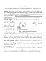
Introduction to Injection Molding and ProPlasticAdvisor
Injection molding is a process that has been used in a wide variety of industries for
many years. This process uses amorphous and crystalline thermoplastic resins that
are heated to a stable temperature and compressed into a mould. The diagram in
Figure below shows the process of injection molding.
Cold polymer is feed from the hopper into the screw where it is heated; the ram then
forces the hot molten polymer into the cold mold. The polymer is then left to cool for
a pre-determined time before the mould is opened and the part is ejected. This
process can be used to produce both simple and very complex components in a very
short time. Examples of familiar products produced by this technique are computer
cases, mobile phones casings, garden chairs etc.
One of the main problems with injection molding is the set up cost; this includes the
mould design, tooling required and the polymer used. This makes it suitable for high
volume production where the cost of molds can be amortized over a large number of
products. To help to reduce the cost of setting up this process Pro/ENGINEER has
designed a package called ProPlasticAdvisor. This package can be used to analyze
the molding process and increase confidence in the design before significant costs
are incurred in mold manufacture.
2
Open the TRAY part
Click
, and proceed to open the
part file of tray.
Transfer to Plastic Advisor
Applications -> Plastic Advisor
Select OK.
3
The PLASTIC
Advisor window
appear.
Click on PLASTIC
Advisor window to
activate it or simply
close the PTC
window.
Maximize the tray
part window.
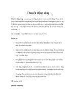
Position the Injection Location
The first step in defining and analysis is to position the injection location, where the
polymer will enter the mould. Consideration must be taken to find the best place to
inject the polymer.
Click on
.
We will inject the polymer from the bottom side of the model. Orientate the part as
shown in the Figure below. Two injection locations will be placed as shown.
4
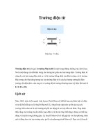
Setup Material and Molding Parameters
The tray is made of Polypropylene (PP). When selecting a polymer for a product the
physical and mechanical properties such as strength, stiffness, hardness, etc. must
be considered.
The diagram in Figure below shows the performance spectrum of plastic materials.
Click
.
5
Select Polypacific as
Manufacturer.
Choose Corton 400 TFHS as
Trade Name.
Click
.
Study carefully the properties
of selected material used to
manufacture this model.
Select
Recommended
Processing for
suggested
processing
conditions
pertaining to
this material.
OK.
6
Select Processing
Conditions tab.
Click OK to accept the
default conditions.
Run the Analysis
Click
.
Click Start to accept Plastic
Flow Analysis as selection
of analysis.
7
On completion of the analysis, a results summary box will appear giving information
on the process and also stating whether the model is suitable for analysis.
The results summary box for this analysis will state that there is a quality problem in
this process – part quality may be unacceptable; we can view the location of these
faults by the following method.
Close.
Investigate the Problem
Adviser -> Adviser…
The Result Advise window appears.
8
Click Quality Prediction tab,
and right-click mouse button
over the part to dynamically
investigate the quality of
molded part.
Right click the area indicated
by yellow, and “Shear stress
exceeds the recommended
limit” will be displayed in the
Results Advice window.
Click
button, and
Advisers Help window
appears.
Note:
If the part is all green, you
don’t need to make any
changes to the analysis.
However, you should still look
at all of the results available,
to confirm that the part is
acceptable. In particular, look
at the air trap and weld line
results.
If the part has red or yellow
areas, find out why the
quality there is low, and try to
make changes to improve the
quality.
9
Study the information
suggested in the help
window.
10
Change the Molding Parameters and Re-Run the Analysis
Click
to modify Molding Parameters. Our goal
this time is to eliminate the high shear stress area
on the model.
11
Un-check Auto injection
time, and enter 1 sec for
Time.
OK.
Click No.
Click
to run again the analysis with longer
injection time.
Results Summary window again indicates the problem of product quality is
unacceptable.
Adviser -> Adviser…
There are several yellow areas on the model. By right-click the yellow areas, we
found the problems are low temperature.
12
Click More button to get Advisers Help.
Click
to modify Molding Parameters, and melt temperature of the material will
be increase.
Change the Melt Temp
to 260.
Run the analysis again.
13
The part quality is
acceptable this time.
Close the results
summary box.
Check For Weld Lines
Click
This will show red lines on the model;
this is where weld lines may form.
Weld lines are where two separate
flows of material within the mould
meet and weld together. They can
cause weaknesses in the final product
and so should be minimized or
avoided.
Check For Air Traps
14
Click
.
This will show blue dots around several places in the model – see figure. This is the
location where air may get trapped in the molding process. Air pockets can result in
incomplete filling of the mould causing weaknesses or poor surface finish in the final
product and so should be minimized or avoided.
Review Fill Time
Select Fill Time from the drop down
menu shown on the left.
15
Then click the play results button
. This will play a small
animation showing the module
filling with polymer and also
gives the fill time on the right
hand side of the screen.
Note:
The software also gives the user
access to information on the
RESULTS pull down menu. This
menu will display the confidence of
fill, fill time, pressure drop, injection
pressure and flow front temp etc.
16
Produce a Web Report
Click
.
Click Next
Enter the necessary
information.
Click Next.
17
Next
To add texts on
Introduction click
located on the right of
.
This will open Notes
editor.
18
Enter the desired information as
introduction for the analysis.
You can write the
summary by selecting
Summary on the left
column, then click
to open the editor.
When all information has
been entered, click
.
19
Select the directory where
you wish to store the
report.
When finished, the resulted report will be displayed – see below:
20
Review the report by selecting the topics
shown on the left.