Tài liệu Signaling Mechanism pdf
Bạn đang xem bản rút gọn của tài liệu. Xem và tải ngay bản đầy đủ của tài liệu tại đây (1.47 MB, 34 trang )
7
Signaling Mechanism
Overview
The module describes RSVP as the signaling mechanism used in QoS enabled
networks. The module builds on knowledge about the IntServ model with the
addition of Common Open Policy Service (COPS) discussed in the introductory
module.
Objectives
Upon completion of this module, you will be able to perform the following tasks:
n Describe Resource Reservation Protocol (RSVP).
n Configure RSVP.
n Describe and configure RSVP on shared media using Subnet Bandwidth
Management (SBM).
n Monitor and troubleshoot RSVP.
7-2 IP QoS Signaling Mechanism Copyright 2001, Cisco Systems, Inc.
Resource Reservation Protocol (RSVP)
Overview
The section introduces Resource Reservation Protocol (RSVP) as the signaling
mechanism in QoS-enabled networks using the Integrated Services model.
Objectives
Upon completion of this lesson, you will be able to perform the following tasks:
n Describe Resource Reservation Protocol (RSVP).
n Configure RSVP.
n Monitor and troubleshoot RSVP.
Copyright 2001, Cisco Systems, Inc. IP QoS Signaling Mechanism 7-3
© 2001, Cisco Systems, Inc. IP QoS Signaling Mechanism-5
Resource Reservation Protocol
Resource Reservation Protocol
• RSVP is a protocol used to reserve resources in a
path between a source and a destination
• RSVP signals all network devices that a certain
application needs certain QoS guarantees
• RSVP requires applications to initiate the request
• RSVP by itself does not provide any guarantees
• An RSVP-interoperable QoS mechanism (WFQ, CB-
WFQ) must be used to implement guarantees
according to RSVP reservations
RSVP is an Internet Engineering Task Force (IETF) signaling protocol, used to
reserve bandwidth in a path between a source and a destination. In RSVP, the
end-node (the application node) station reserves bandwidth for a flow along its path
to a destination in a network. The user can supply the information about how much
capacity to reserve.
RSVP mechanisms enable real-time traffic to reserve bandwidth necessary for
consistent latency. A video conferencing application can use settings in the router
to propagate a request for a path with the required bandwidth and delay for video
conferencing destinations. RSVP then signals all network devices along the path,
and confirms or rejects the reservation. RSVP will check and repeat reservations
at regular intervals. When RSVP is used, the routers sort and prioritize packets
much as a statistical time-division multiplexer would sort and prioritize several
signal sources that share a single channel.
RSVP requires RSVP-aware applications, as signaling is performed by the end-
node. In addition, RSVP does not provide any guarantees by itself. RSVP is the
protocol used to communicate QoS requirements between the end-node and the
layer-3 network, assessing the ability or inability of the network to support the
requested level of service.
RSVP is the signaling protocol underlying the IntServ QoS reference model.
Together with appropriate QoS-enforcing mechanisms in the network, such as
WFQ, it forms a foundation for implementation of IntServ-based services.
7-4 IP QoS Signaling Mechanism Copyright 2001, Cisco Systems, Inc.
© 2001, Cisco Systems, Inc. IP QoS Signaling Mechanism-6
End-to-end RSVP
End-to-end RSVP
• All network devices have to be enabled for
RSVP
• Each network device determines whether it
has enough resources
request request request request
reservereservereservereserve
Local
Admission
Control
Local
Admission
Control
Local
Admission
Control
If end-to-end RSVP is desired in a network, all devices in the reservation path
must be RSVP-enabled. When a device receives an RSVP message, it determines
whether it has enough resources to satisfy the reservation request at the local
level.
There are two main RSVP messages used for signaling. When a reservation is
needed, the sending client sends an RSVP PATH message into the network
requesting a specific bandwidth to a specific destination (or multicast address, in
the case of IP multicast application). The purpose of the PATH message is to
discover all RSVP-enabled routers along the path from the sender to the receiver,
and to create initial reservations. The PATH message is forwarded along the flow
path and every intermediate RSVP-capable router adds its identification to the
PATH message. When the receiving end-node receives the PATH message, it
confirms the reservation by replying with an RSVP RESV message. The RESV
message is forwarded back upstream towards the initial sender using the list of
RSVP-enabled routers generated by the PATH message. If the RESV message
successfully arrives at the initial sender, each hop in the end-to-end connection has
reserved the appropriate resources and an end-to-end reservation is established. If
the appropriate resources are not available, the reservation is refused and the
application must default to traditional, best effort communications.
RSVP keeps track of the soft state of reservations in routers. This soft state
provides dynamic membership information, adapts to routing changes, and, as the
number of flows increases, enables dynamic changes in reservations to meet those
changing needs. RSVP reservations time out unless periodically refreshed by the
communication endpoint, usually at 30-second intervals.
The benefits of soft state behavior are:
Copyright 2001, Cisco Systems, Inc. IP QoS Signaling Mechanism 7-5
n Connectionless behavior − routers automatically adapt to route changes.
n Timeliness − state changes propagate immediately, but only as far as needed.
n Robustness − the method is self-correcting, because incorrect reservations
will always time-out even in the most unexpected situations.
n Flexibility − provides easy dynamic reservation changes.
The cost of this approach is that it requires ongoing refresh processing for
established states by the endpoints.
7-6 IP QoS Signaling Mechanism Copyright 2001, Cisco Systems, Inc.
© 2001, Cisco Systems, Inc. IP QoS Signaling Mechanism-7
Pass-through RSVP
Pass-through RSVP
• Part of the network may not support RSVP
• Best-effort delivery is used in those parts
request
request
request
reserve
reserve
reserve
Local
Admission
Control
Local
Admission
Control
Best-effort
forwarding
RSVP
not
enabled
request request
reservereserve
Local
Admission
Control
When a part of the network does not support RSVP, that is, when the RSVP
messages are not processed by every intermediate hop between the two
application endpoints, some other mechanism may be employed to try to meet the
application requirements in the non-RSVP-enabled part of the network. One such
possibility may be to perform only best-effort delivery between RSVP-enabled
networks using an undersubscribed network in between. The PATH messages
discover all RSVP-aware routers, and are forwarded as plain IP packets on non-
RSVP-enabled hops. The RESV messages are then interpreted only by the RSVP-
aware hops, discovered via the PATH message.
Copyright 2001, Cisco Systems, Inc. IP QoS Signaling Mechanism 7-7
© 2001, Cisco Systems, Inc. IP QoS Signaling Mechanism-8
Pass-through RSVP
with Class of Service
Pass-through RSVP
with Class of Service
• Part of the network may not support RSVP
• Mark RSVP flows with a Class-of-service
marker (e.g. IP precedence or DSCP)
• Make sure the core provides guarantees to
the RSVP class
request
request
request
reserve
reserve
reserve
Local
Admission
Control
Local
Admission
Control
RSVP
not
enabled
request request
reservereserve
Mark RSVP flow
with DSCP
Local
Admission
Control
Class-based
guarantee
Another option may be to apply class-of-service based delivery on a non-RSVP-
enabled part of the network. In that case, RSVP-based application traffic is
marked with appropriate class markers (IP precedence or DSCP bits) at the entry
to the non-RSVP-enabled part. The core network can then be engineered to
provide special service to the RSVP class, using, for example, WFQ and WRED.
IP precedence and DSCP are packet markers, located in the ToS byte of the IP
header, which identify traffic classes on each hop in the network. IP precedence
or DSCP bits are usually set at the network edge, where traffic is classified and
marked, and the markers used to identify traffic classes in downstream network
devices. Each device along the path may apply appropriate QoS mechanisms
based on the packet marker, resulting in differentiated per-hop behaviour (PHB)
for each class of traffic. The DiffServ model defines several standard PHBs,
based on marking traffic with the DSCP header bits.
7-8 IP QoS Signaling Mechanism Copyright 2001, Cisco Systems, Inc.
© 2001, Cisco Systems, Inc. IP QoS Signaling Mechanism-9
RSVP Applications
RSVP Applications
• RSVP is used for applications where
bandwidth and delay related guarantees are
necessary
• Typical applications are:
– Voice over IP (Cisco phones, Microsoft
NetMeeting, )
– MPLS Traffic Engineering
RSVP allows end systems to request QoS guarantees from the network. The need
for network resource reservations differs for data traffic versus real-time traffic,
as described in the following paragraphs:
n Data traffic seldom needs reserved bandwidth because internetworks provide
datagram services for data traffic. This asynchronous packet switching may
not need guarantees of service quality. End-to-end controls between data
traffic senders and receivers help ensure adequate transmission of bursts of
information.
n Real-time traffic (that is, voice or video information) experiences problems
when using datagram services. Because real-time traffic sends an almost
constant flow of information, the network “pipes” must be consistent. Some
guarantee must be provided that service between real-time hosts will not vary.
Routers operating on a first-in, first-out (FIFO) basis risk unrecoverable
disruption of the real-time information that is being sent.
Many network-aware applications today use RSVP for signaling. Some well-
known examples include Cisco IP telephones, Microsoft NetMeeting, and MPLS
Traffic Engineering.
Copyright 2001, Cisco Systems, Inc. IP QoS Signaling Mechanism 7-9
© 2001, Cisco Systems, Inc. IP QoS Signaling Mechanism-10
Configuring Simple RSVP
Configuring Simple RSVP
ip rsvp bandwidth [total-BW [per-flow-BW]]
ip rsvp bandwidth [total-BW [per-flow-BW]]
Router(config-if)#
• Set the amount of reservable bandwidth (total-BW) and the
maximum per-flow reservable bandwidth (per-flow-BW) in kbps
• Both default to 75% of the configured bandwidth
• Total reservable bandwidth cannot exceed 75% of the
configured bandwidth
bandwidth bandwidth
bandwidth bandwidth
Router(config-if)#
• Set the interface bandwidth in kbps
• This value should reflect the real bandwidth of the link
Basic RSVP is configured by two interface commands. The ip rsvp bandwidth
command sets the maximum total amount of reservable bandwidth on an interface.
By default, it is configured to 75% of the configured bandwidth, which is also its
maximum allowed value. A per-flow reservable bandwidth can also be configured,
setting the maximum bandwidth a single flow can reserve over this interface. By
default, it is also set to 75% of the configured bandwidth.
Note RSVP cannot be configured with VIP-distributed Cisco Express Forwarding
(dCEF).
The bandwidth interface command sets the interface bandwidth and is used by
routing protocols (to calculate costs) and by a variety of QoS mechanisms. With
RSVP, this is used as the configured bandwidth parameter, referenced by the limits
in the ip rsvp bandwidth command.
7-10 IP QoS Signaling Mechanism Copyright 2001, Cisco Systems, Inc.
© 2001, Cisco Systems, Inc. IP QoS Signaling Mechanism-11
Configuring Proxy RSVP
Configuring Proxy RSVP
ip rsvp sender session-IP sender-IP protocol dport sport src-hop-
IP src-intf bandwidth burst
ip rsvp sender session-IP sender-IP protocol dport sport src-hop-
IP src-intf bandwidth burst
Router(config)#
• Simulates a host sending a PATH message
• Generates a PATH message on behalf of a host or an
application
ip rsvp reservation session-IP sender-IP protocol dport sport
next-hop-IP next-hop-intf {ff | se | wf} {rate | load} bw burst
ip rsvp reservation session-IP sender-IP protocol dport sport
next-hop-IP next-hop-intf {ff | se | wf} {rate | load} bw burst
Router(config)#
• Simulates a host sending a RESV message
• Generates a RESV message on behalf of a host or an
application
RSVP typically requires both host and network implementations, although Cisco
IOS software provides an RSVP command line interface that allows you to
statically set up RSVP reservations without host involvement.
Use the ip rsvp sender command to make the router simulate that it is receiving
RSVP PATH messages from an upstream host. The command can be used to
proxy RSVP PATH messages for non-RSVP-capable senders. By including a
local (loopback) previous hop address and previous hop interface, you can also use
this command to proxy RSVP for the router you are configuring.
To enable a router to simulate receiving and forwarding Resource Reservation
Protocol (RSVP) RESV messages, use the ip rsvp reservation global
configuration command. To disable this feature, use the no form of this command.
Use this command to make the router simulate receiving RSVP RESV messages
from a downstream host. This command can be used to proxy RSVP RESV
messages for non-RSVP-capable receivers. By giving a local (loopback) next hop
address and next hop interface, you can also use this command to proxy RSVP for
the router you are configuring. Several different reservation types can be specified.
For detailed reservation settings, consult the Cisco IOS documentation.
Copyright 2001, Cisco Systems, Inc. IP QoS Signaling Mechanism 7-11
© 2001, Cisco Systems, Inc. IP QoS Signaling Mechanism-12
RSVP Admission Control
RSVP Admission Control
• RSVP has two tasks:
– Determine if there are enough available resources
– Determine if the application in question is allowed
access to these resources
• RSVP-enabled devices keep track of existing
reservations locally
• RSVP-enabled devices can offload the
authorization part of admission control to
central servers (COPS)
A RSVP-enabled router therefore needs to perform two tasks:
n The router needs to determine whether there are currently available resources,
which can be used to satisfy the reservation request.
n The router needs to be able to authorize an application to make the reservation
request (admission control).
The first task can be performed by keeping track of existing reservations, and of
total reservable capacity locally on each device. If a reservation request exceeds
the locally available reservable resources, the reservation request is denied.
Authorization of reservations could be performed locally, but such an approach
would not scale to more than a few devices. Fortunately, there is a standardized,
centralized framework for policy networking, which includes authorization within
admission control. This framework is based on a set of services and protocols
called the Common Open Policy Service (COPS).
7-12 IP QoS Signaling Mechanism Copyright 2001, Cisco Systems, Inc.
© 2001, Cisco Systems, Inc. IP QoS Signaling Mechanism-13
Common Open Policy Service
Common Open Policy Service
• COPS allows a more centralized approach to
building RSVP enabled networks (more scalable)
• COPS provides additional control over who can
reserve what
request request request request
reservereservereservereserve
Local
Admission
Control
Remote Admission
Control
Local
Admission
Control
Policy Decision
Point (PDP)
request
reply
Policy Enforcement
Point (PEP)
Common Open Policy Service (COPS) is an open framework designed for
management in policy networking. COPS provides a service to network devices
and implements management protocols, which enable scalable provisioning of
Quality of Service policies in a network.
COPS is designed so that it provides a centrally managed, but distributed system
for configuring network devices according to centralized policy decisions. In the
case of RSVP, COPS provides centralized databases, which network devices
query for reservation/admission control information. RSVP-enabled devices
therefore need no locally stored configuration, but receive this information in real-
time from the appropriate COPS server. COPS, therefore, scales QoS
provisioning, and enables a device-independent QoS policy throughout the network.
COPS defines the following types of policy services:
n The Policy Enforcement Point (PEP) is the device that enforces network
policy (a router performing RSVP admission control, a firewall filtering traffic).
n The Policy Decision Point (PDP) is the device that stores policy information
and makes it available to the PEP devices.
Copyright 2001, Cisco Systems, Inc. IP QoS Signaling Mechanism 7-13
© 2001, Cisco Systems, Inc. IP QoS Signaling Mechanism-14
Configuring RSVP for COPS
Configuring RSVP for COPS
Process
Locally?
Reject?
Process
Message
Reject Message
Send an error
message to the
source
Yes Yes
No No
Local
Override?
Yes
Default
Local
Policy?
Yes
Process
Remotely?
Ask
PDP
No
No
Reject?
No
Yes
No
Yes
Default
Reject?
No
No
Yes
ip rsvp policy local acl
ip rsvp policy local
ip rsvp policy local local-override
Default
Remote
Policy?
The figure shows the flowchart used to consult either the local policy settings, or
the COPS service. Both the local policy and the COPS service can be used
simultaneously on the same router. Individual COPS commands are also presented
in the flowchart, next to the functions they enable.
The admission process in policy networking proceeds as follows for locally
processed messages:
n The router receives a PATH or RESV message and first tries to adjudicate it
locally (that is, without referring to the policy server). If the router has been
configured to adjudicate specific access control lists (ACLs) locally and the
message matches one of those lists, the policy module of the router applies the
operators with which it had been configured. Otherwise, policy processing
continues.
n For each message rejected by the operators, the router sends an error
message to the sender and removes the PATH or RESV message from the
database. If the message is not rejected, policy processing continues.
n If the local override flag is set for this entry, the message is immediately
accepted with the specified policy operators. Otherwise, policy processing
continues.
7-14 IP QoS Signaling Mechanism Copyright 2001, Cisco Systems, Inc.
© 2001, Cisco Systems, Inc. IP QoS Signaling Mechanism-15
Configuring RSVP for COPS
(cont.)
Configuring RSVP for COPS
(cont.)
Process
Locally?
Reject?
Process
Message
Reject Message
Send an error
message to the
source
Yes Yes
No No
Local
Override?
Yes
Default
Local
Policy?
Yes
Process
Remotely?
Ask
PDP
No
No
Reject?
No
Yes
No
Yes
Default
Reject?
No
No
Yes
ip rsvp policy cops acl servers
ip rsvp policy default-reject
Default
Remote
Policy?
ip rsvp policy cops servers
If policy decisions are offloaded to a policy server, policy processing continues as
follows:
n If the message does not match any ACL configured for local policy, the router
applies the default local policy. However, if no default local policy has been
configured, the message is directed toward remote policy processing.
n If the router has been configured with specific ACLs against specific policy
servers (more specifically, PDPs), and the message matches one of these
ACLs, the router sends that message to the specific PDP for adjudication.
Otherwise, policy processing continues.
n If the PDP specifies a “reject” decision, the message is discarded and an error
message is sent back to the sender, indicating this condition. If the PDP
specifies an “accept” decision, the message is accepted and processed using
normal RSVP processing rules.
n If the message does not match any ACL configured for specific PDPs, the
router applies the default PDP configuration. If a default COPS configuration
has been entered, policy processing continues. Otherwise, the message is
considered to be unmatched.
n If the default policy decision for unmatched messages is to reject, the message
is immediately discarded and an ERROR message is sent to the sender
indicating this condition. Otherwise, the message is accepted and processed
using normal RSVP processing rules.
Whenever a request for adjudication (of any sort) is sent to a PDP, a 30-second
timer associated with the PATH or RESV message is started. If the timer runs out
Copyright 2001, Cisco Systems, Inc. IP QoS Signaling Mechanism 7-15
before the PDP replies to the request, the PDP is assumed to be down and the
request is given to the default policy.
7-16 IP QoS Signaling Mechanism Copyright 2001, Cisco Systems, Inc.
© 2001, Cisco Systems, Inc. IP QoS Signaling Mechanism-15
RSVP
Example
RSVP
Example
interface Serial0/0
bandwidth 256
ip address 10.5.8.65 255.255.255.252
encapsulation ppp
fair-queue 64 256 20
ip rtp header-compression
ip rsvp bandwidth 160
interface Serial0/0
bandwidth 128
ip address 10.10.3.33 255.255.255.252
encapsulation ppp
fair-queue 64 256 10
ip rtp header-compression
ip rsvp bandwidth 80
The figure shows a basic example of RSVP configuration in Cisco IOS routers.
The two routers in the figure are both configured for RSVP, and both utilize WFQ
to guarantee bandwidth to RSVP flows in RSVP-reserved queues. Different
maximum reservable bandwidths are allocated, based on the real bandwidth of the
link.
Copyright 2001, Cisco Systems, Inc. IP QoS Signaling Mechanism 7-17
© 2001, Cisco Systems, Inc. IP QoS Signaling Mechanism-16
RSVP with COPS
Example
RSVP with COPS
Example
interface Serial0/0
bandwidth 2048
ip address 10.1.1.1 255.255.255.252
encapsulation ppp
fair-queue 64 256 100
ip rsvp bandwidth 512
!
ip rsvp policy cops 100 servers 10.100.1.1 10.101.1.1
ip rsvp policy default-reject
ip rsvp policy cops minimal
ip rsvp policy cops timeout 600
ip rsvp policy cops report-all
!
access-list 100 permit udp any any
COPS
(PEP)
COPS
(PDP)
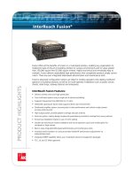
This figure shows a COPS-enabled RSVP configuration. The RSVP interface
configuration does not change, and COPS parameters are defined with the ip rsvp
policy commands. In this example, the COPS PDP adjudicates all UDP traffic
reservations.
7-18 IP QoS Signaling Mechanism Copyright 2001, Cisco Systems, Inc.
© 2001, Cisco Systems, Inc. IP QoS Signaling Mechanism-17
Monitoring and Troubleshooting
RSVP
Monitoring and Troubleshooting
RSVP
show ip rsvp installed [detail]show ip rsvp installed [detail]
Router#
• Lists installed reservations per interface
Router#show ip rsvp installed
RSVP:Ethernet2/1
BPS To From Protoc DPort Sport Weight
Conversation
44K 145.20.0.202 145.10.0.201 UDP 1000 1000 0 264
44K 145.20.0.202 145.10.0.201 UDP 1001 1001 13 266
98K 145.20.0.202 145.10.0.201 UDP 1002 1002 6 265
1K 145.20.0.202 145.10.0.201 UDP 10 10 0 264
RSVP:Serial3/0 has no installed reservations
The show ip rsvp installed command shows all active conversations over an
RSVP-enabled path, which has resource reservations installed. The actual
reserved bandwidth is shown, along with the session parameters (endpoints and
applications).
Copyright 2001, Cisco Systems, Inc. IP QoS Signaling Mechanism 7-19
© 2001, Cisco Systems, Inc. IP QoS Signaling Mechanism-18
Monitoring and Troubleshooting
RSVP
Monitoring and Troubleshooting
RSVP
show ip rsvp installed [detail] [interface]show ip rsvp installed [detail] [interface]
Router#
Router#show ip rsvp installed detail
RSVP:Ethernet2/1 has the following installed reservations
RSVP Reservation. Destination is 145.20.0.202, Source is 145.10.0.201,
Protocol is UDP, Destination port is 1000, Source port is 1000
Reserved bandwidth:44K bits/sec, Maximum burst:1K bytes, Peak rate: 44K bits/sec
QoS provider for this flow:WFQ. Conversation number:264. Weight:0 (PQ)
Conversation supports 1 reservations
Data given reserved service:316 packets (15800 bytes)
Data given best-effort service:0 packets (0 bytes)
Reserved traffic classified for 104 seconds
Long-term average bitrate (bits/sec):1212 reserved, 0M best-effort
RSVP Reservation. Destination is 145.20.0.202, Source is 145.10.0.201,
Protocol is UDP, Destination port is 1001, Source port is 1001
Reserved bandwidth:44K bits/sec, Maximum burst:3K bytes, Peak rate: 44K bits/sec
QoS provider for this flow:WFQ. Conversation number:266. Weight:13
Conversation supports 1 reservations
Data given reserved service:9 packets (450 bytes)
Data given best-effort service:0 packets (0 bytes)
Reserved traffic classified for 107 seconds
Long-term average bitrate (bits/sec):33 reserved, 0M best-effort
The show ip rsvp installed detail command shows detailed information about
active conversations currently installed in the RSVP reservation table. Detailed
timing and accounting for every conversation is displayed, together with the QoS
mechanism used to provide service guarantees.
7-20 IP QoS Signaling Mechanism Copyright 2001, Cisco Systems, Inc.
© 2001, Cisco Systems, Inc. IP QoS Signaling Mechanism-19
Monitoring and Troubleshooting
RSVP
Monitoring and Troubleshooting
RSVP
show ip rsvp reservation [detail]
show ip rsvp reservation [detail]
Router(config)#
• List RSVP reservations
show ip rsvp request [detail]
show ip rsvp request [detail]
Router(config)#
• List pending RSVP requests
The show ip rsvp reservation command lists all existing RSVP reservations over
an interface. The show ip rsvp request command shows all pending RSVP
requests that have no fixed reservation in place.
Copyright 2001, Cisco Systems, Inc. IP QoS Signaling Mechanism 7-21
© 2001, Cisco Systems, Inc. IP QoS Signaling Mechanism-20
Monitoring and Troubleshooting
RSVP with COPS
Monitoring and Troubleshooting
RSVP with COPS
show ip rsvp policy [{cops | local} [acl]]show ip rsvp policy [{cops | local} [acl]]
Router#
Router#show ip rsvp policy cops
COPS/RSVP settings:
Generate reports for all decisions
Do not query PDP for error messages
COPS/RSVP entry. ACLs: 100
PDPs: 10.100.1.1 10.101.1.1
Current state: Connected
Currently connected to PDP 10.100.1.1, port 0
COPS/RSVP entry. ACLs: 101
PDPs: 10.102.1.1
Current state: In reconnect loop wait
Reconnect timer is 960 seconds
• Lists all policies
The show ip rsvp policy command shows the policy settings, whether the policy
is locally defined or policy decisions are offloaded to the COPS server. The output
shows associations between flow specifications and associated COPS servers,
which perform admission control for those flows. This command is used to verify
connectivity to COPS services and the associations between the local device and a
COPS server.
7-22 IP QoS Signaling Mechanism Copyright 2001, Cisco Systems, Inc.
© 2001, Cisco Systems, Inc. IP QoS Signaling Mechanism-21
Monitoring and Troubleshooting
RSVP with COPS
Monitoring and Troubleshooting
RSVP with COPS
show cops serversshow cops servers
Router#
Router#show cops servers
COPS SERVER: Address: 10.100.1.1. Port: 3288. State: 0. Keepalive: 120 sec
Number of clients: 1. Number of sessions: 1.
COPS CLIENT: Client type: 1. State: 0.
Router#show cops servers
COPS SERVER: Address: 10.100.1.1. Port: 3288. State: 0. Keepalive: 120 sec
Number of clients: 1. Number of sessions: 1.
COPS CLIENT: Client type: 1. State: 0.
• Lists all COPS servers
The show cops servers command displays the state of all configured COPS
servers.
Copyright 2001, Cisco Systems, Inc. IP QoS Signaling Mechanism 7-23
Summary
n RSVP enables end-stations to signal QoS requirements to the network.
n RSVP does not provide any guarantees; router QoS mechanisms do.
n RSVP does not necessarily require an end-to-end RSVP-aware path.
n COPS provides scalable QoS provisioning.
Lesson Review
1. What is RSVP used for?
2. Does RSVP provide QoS guarantees?
3. What QoS mechanism should be used to provide QoS guarantees to RSVP
reservations?
4. What are the benefits of using COPS with RSVP?
7-24 IP QoS Signaling Mechanism Copyright 2001, Cisco Systems, Inc.
Subnet Bandwidth Management
Overview
This section describes a mechanism that is used on shared media where more
complex reservation is required. SBM protocol is used between RSVP devices
reachable over the same subnet.
Objectives
Upon completion of this lesson, you will be able to perform the following tasks:
n Describe Subnet Bandwidth Management (SBM).
n Configure SBM.
n Monitor and troubleshoot RSVP with SBM.
Copyright 2001, Cisco Systems, Inc. IP QoS Signaling Mechanism 7-25
© 2001, Cisco Systems, Inc. IP QoS Signaling Mechanism-26
Subnet Bandwidth Management
Subnet Bandwidth Management
• RSVP manages unidirectional reservation of
resources
• RSVP on shared media can result in
oversubscription
• SBM is an add-on to RSVP on shared media
to prevent oversubscription
RSVP is used to manage reservation of resources unidirectionally, between Layer-
3 hops. On a shared medium, many Layer-3 hops can be active between many
routers on the shared segment. The shared medium is shared between all routers,
therefore the routers need to keep track about all routers’ usage of the shared
medium, in order to maintain a consistent picture of available bandwidth on that
medium. If routers were independently reserving bandwidth over a shared medium,
oversubscription would occur if each router had full access to the medium
bandwidth.
Subnet Bandwidth Management (SBM) is an add-on to the RSVP protocol, which
provides arbitration of bandwidth allocation on a shared medium to prevent RSVP-
caused oversubscription. SBM specifies a signaling method and protocol for LAN-
based admission control for RSVP flows. SBM allows RSVP-enabled routers and
Layer 2 and Layer 3 devices to support reservation of LAN resources for RSVP-
enabled data flows. The SBM signaling method is similar to that of RSVP itself.