condition assessment of high voltage insulation in power system equipment pdf
Bạn đang xem bản rút gọn của tài liệu. Xem và tải ngay bản đầy đủ của tài liệu tại đây (2.12 MB, 290 trang )
IET POWER AND ENERGY SERIES 53
Condition Assessment
of High Voltage
Insulation in Power
System Equipment
www.EngineeringBooksPDF.com
Other volumes in this series:
Volume 1
Volume 4
Volume 7
Volume 8
Volume 10
Volume 11
Volume 13
Volume 14
Volume 15
Volume 16
Volume 18
Volume 19
Volume 21
Volume 22
Volume 24
Volume 25
Volume 26
Volume 27
Volume 29
Volume 30
Volume 31
Volume 32
Volume 33
Volume 34
Volume 35
Volume 36
Volume 37
Volume 38
Volume 39
Volume 40
Volume 41
Volume 43
Volume 44
Volume 45
Volume 46
Volume 47
Volume 48
Volume 49
Volume 50
Volume 51
Volume 52
Volume 905
Power circuit breaker theory and design C.H. Flurscheim (Editor)
Industrial microwave heating A.C. Metaxas and R.J. Meredith
Insulators for high voltages J.S.T. Looms
Variable frequency AC-motor drive systems D. Finney
SF6 switchgear H.M. Ryan and G.R. Jones
Conduction and induction heating E.J. Davies
Statistical technjiques for high voltage engineering W. Hauschild and
W. Mosch
Uninterruptible power supplies J. Platts and J.D. St Aubyn (Editors)
Digital protection for power systems A.T. Johns and S.K. Salman
Electricity economics and planning T.W. Berrie
Vacuum switchgear A. Greenwood
Electrical safety: a guide to causes and prevention of hazards J. Maxwell
Adams
Electricity distribution network design, 2nd edition E. Lakervi and
E.J. Holmes
Artificial intelligence techniques in power systems K. Warwick,
A.O. Ekwue and R. Aggarwal (Editors)
Power system commissioning and maintenance practice K. Harker
Engineers’ handbook of industrial microwave heating R.J. Meredith
Small electric motors H. Moczala et al.
AC–DC power system analysis J. Arrillaga and B.C. Smith
High voltage direct current transmission, 2nd edition J. Arrillaga
Flexible AC Transmission Systems (FACTS) Y-H. Song (Editor)
Embedded generation N. Jenkins et al.
High voltage engineering and testing, 2nd edition H.M. Ryan (Editor)
Overvoltage protection of low-voltage systems, revised edition P. Hasse
The lighting flash V. Cooray
Control techniques drives and controls handbook W. Drury (Editor)
Voltage quality in electrical power systems J. Schlabbach et al.
Electrical steels for rotating machines P. Beckley
The electric car: development and future of battery, hybrid and
fuel-cell cars M. Westbrook
Power systems of electromagnetic transients simulation J. Arrillaga and
N. Watson
Advances in high voltage engineering M. Haddad and D. Warne
Electrical operation of electrostatic precipitators K. Parker
Thermal power plant simulation and control D. Flynn
Economic evaluation of projects in the electricity supply industry
H. Khatib
Propulsion systems for hybrid vehicles J. Miller
Distribution switchgear S. Stewart
Protection of electricity distribution networks, 2nd edition J. Gers and
E. Holmes
Wood pole overhead lines B. Wareing
Electric fuses, 3rd edition A. Wright and G. Newbery
Wind power integration: connection and system operational aspects
B. Fox et al.
Short circuit currents J. Schlabbach
Nuclear power J. Wood
Power system protection, 4 volumes
www.EngineeringBooksPDF.com
Condition Assessment
of High Voltage
Insulation in Power
System Equipment
R.E. James and Q. Su
The Institution of Engineering and Technology
www.EngineeringBooksPDF.com
Published by The Institution of Engineering and Technology, London, United Kingdom
© 2008 The Institution of Engineering and Technology
First published 2008
This publication is copyright under the Berne Convention and the Universal Copyright
Convention. All rights reserved. Apart from any fair dealing for the purposes of research
or private study, or criticism or review, as permitted under the Copyright, Designs and
Patents Act, 1988, this publication may be reproduced, stored or transmitted, in any
form or by any means, only with the prior permission in writing of the publishers, or in
the case of reprographic reproduction in accordance with the terms of licences issued
by the Copyright Licensing Agency. Enquiries concerning reproduction outside those
terms should be sent to the publishers at the undermentioned address:
The Institution of Engineering and Technology
Michael Faraday House
Six Hills Way, Stevenage
Herts, SG1 2AY, United Kingdom
www.theiet.org
While the authors and the publishers believe that the information and guidance given
in this work are correct, all parties must rely upon their own skill and judgement when
making use of them. Neither the authors nor the publishers assume any liability to
anyone for any loss or damage caused by any error or omission in the work, whether
such error or omission is the result of negligence or any other cause. Any and all such
liability is disclaimed.
The moral rights of the authors to be identified as authors of this work have been
asserted by them in accordance with the Copyright, Designs and Patents Act 1988.
British Library Cataloguing in Publication Data
James, R. E.
Condition assessment of high voltage insulation in power
system equipment. - (Power & energy series; v. 53)
1. Electric insulators and insulation - Testing 2. High Voltages
I. Title II. Su, Q. III. Institution of Engineering and Technology
621.3’1937
ISBN 978-0-86341-737-5
Typeset in India by Newgen Imaging Systems (P) Ltd, Chennai
Printed in the UK by Athenaeum Press Ltd, Gateshead, Tyne & Wear
www.EngineeringBooksPDF.com
Contents
Preface
xi
1
Introduction
1.1
Interconnection of HV power system components
1.1.1
Alternating voltage systems
1.1.2
Direct-voltage systems
1.2
Insulation coordination
1.3
High-voltage test levels
1.3.1
Power-frequency voltages
1.3.2
Lightning-impulse voltages
1.3.3
Switching surges
1.3.4
Very fast transient tests (VFTT)
1.3.5
Direct-voltage tests
1.4
Power system developments
1.4.1
Reliability requirements
1.4.2
Condition of present assets
1.4.3
Extension of power system life
1.4.4
New systems and equipment
1.5
Future insulation monitoring requirements
1.6
Summary
1.7
References
1.8
Problems
1
2
2
8
9
10
13
13
14
14
14
15
15
15
16
16
17
17
17
18
2
Insulating materials utilized in power-system equipment
2.1
Review of insulating materials
2.1.1
Gases
2.1.2
Vacuum
2.1.3
Liquids
2.1.4
Solids
21
22
22
25
25
27
www.EngineeringBooksPDF.com
vi
Condition Assessment of High-Voltage Insulation
2.2
2.3
2.4
2.5
2.6
2.7
2.8
2.9
Characterization of insulation condition
2.2.1
Permittivity (ε) and capacitance (C)
2.2.2
Resistivity (ρ) and insulation resistance (IR)
2.2.3
Time constants
2.2.4
Dielectric dissipation factor
2.2.5
Partial discharges (PD)
2.2.6
Physical and chemical changes
Modes of deterioration and failure of practical insulating
materials
2.3.1
Dielectric losses
2.3.2
Partial discharges – sources, forms and effects
2.3.3
Ageing effects
Electrical breakdown and operating stresses
Development of insulation applications
Summary
References
Standards related to insulating materials
Problems
33
33
33
34
34
35
35
36
37
39
46
48
50
50
51
53
54
3
Introduction to electrical insulation design concepts
3.1
Overview of insulation design requirements
3.1.1
Electrical requirements
3.1.2
Physical limitations
3.1.3
Working environment
3.1.4
Mechanical requirements
3.1.5
Thermal conditions
3.1.6
Processing
3.1.7
Reliability
3.2
Electric stress distributions in simple insulation systems
3.2.1
Multiple dielectric systems
3.2.2
Edge effects
3.2.3
Multiple electrode configurations
3.3
Electric stress control
3.4
Summary
3.5
References
3.6
Problems
55
55
56
56
56
57
58
58
59
60
61
64
66
68
69
69
70
4
Insulation defects in power-system equipment: Part 1
4.1
Suspension and post insulators
4.1.1
Suspension (string) insulators
4.1.2
Post insulators
4.2
High-voltage bushings
4.3
High-voltage instrument transformers
4.3.1
Oil-impregnated current transformers
4.3.2
Dry-type current transformers
4.3.3
Capacitor-type voltage transformers – CVT
71
71
71
73
74
77
78
80
81
www.EngineeringBooksPDF.com
List of contents
4.4
4.5
4.6
4.7
4.8
4.9
4.10
4.11
4.12
5
6
High-voltage power capacitors
High-voltage surge arresters
High-voltage circuit breakers
Gas-insulated systems (GIS)
High-voltage cables
4.8.1
Oil–paper cables
4.8.2
Extruded cables
Summary
References
Standards related to Chapter 4
Problems
Insulation defects in power-system equipment: Part 2
5.1
Electrical rotating machines
5.1.1
Low-voltage motors
5.1.2
High-voltage machines
5.1.3
Possible insulation failure mechanisms in rotating
machines
5.1.4
CIGRE summary of expected machine insulation
degradation
5.1.5
Future of machine insulation
5.2
Transformers and reactors
5.2.1
Windings
5.2.2
Transformer insulation structures
5.3
Summary
5.4
References
5.5
Problems
Basic methods for insulation assessment
6.1
Generation and measurement of test high voltages
6.1.1
Power-frequency voltages
6.1.2
High-frequency voltages
6.1.3
Very-low-frequency voltages (VLF)
6.1.4
Direct voltages
6.1.5
Hybrid test circuits
6.1.6
Lightning impulse voltages
6.1.7
Switching surge voltages
6.1.8
High-voltage equipment for on-site testing
6.2
Non-destructive electrical measurements
6.2.1
Insulation resistance (IR) measurements
6.2.2
Measurements of the dielectric dissipation factor
(DDF)
6.2.3
Measurement of partial discharges by electrical
methods
6.2.4
Dielectric response measurements
www.EngineeringBooksPDF.com
vii
82
83
84
86
87
87
90
93
93
95
96
97
97
97
98
100
103
103
104
104
106
118
118
120
121
122
122
127
128
128
129
129
133
133
135
135
137
140
147
viii
Condition Assessment of High-Voltage Insulation
6.3
6.4
6.5
6.6
6.7
7
Physical and chemical diagnostic methods
6.3.1
Indicators of in-service condition of oil–paper
systems
6.3.2
Analysis of SF6 samples from GIS
6.3.3
Surface deterioration of composite insulators
6.3.4
Water treeing in XLPE cable insulation
6.3.5
Ultrasonic methods for detection of partial
discharges
6.3.6
Miscellaneous techniques
Summary
References
Standards related to basic test methods
Problems
Established methods for insulation testing of specific equipment
7.1
Overhead line and substation insulators
7.1.1
Porcelain and glass insulators (overhead lines)
7.1.2
Ceramic and glass insulators (post type – indoor and
outdoor)
7.1.3
Composite insulators for overhead lines (string and post
units)
7.2
Overhead line and substation hardware
7.3
Surge arresters
7.4
Switchgear
7.4.1
Circuit breakers
7.4.2
Self-protected switchgear
7.4.3
Disconnectors (isolators)
7.4.4
Metal-enclosed switchgear
7.4.5
Transformer tap changers
7.5
Bushings
7.6
High-voltage instrument transformers
7.6.1
Current transformers
7.6.2
Inductive voltage transformers
7.6.3
Capacitor voltage transformers
7.7
High-voltage power capacitors
7.8
High-voltage rotating machines
7.8.1
Stator bars
7.8.2
Assembled machine
7.9
High-voltage cables
7.9.1
Oil-impregnated cables
7.9.2
Extruded cables
7.10 Distribution and power transformers
7.10.1 Power-frequency overvoltage withstand tests
7.10.2 Partial-discharge tests
7.10.3 Summary of transformer HV test requirements
www.EngineeringBooksPDF.com
150
150
153
153
153
154
154
154
154
157
158
159
160
161
161
162
162
163
164
164
166
166
166
167
167
168
168
169
170
171
171
172
172
173
173
173
175
175
177
180
List of contents
7.11
7.12
7.13
7.14
7.15
7.16
8
9
7.10.4 Additional tests
Dielectric testing of HVDC equipment
Miscellaneous items
Summary
References
Standards related to Chapter 7
Problems
ix
182
182
184
184
184
185
188
Sensors for insulation condition monitoring
8.1
Ultra-high-frequency sensors
8.2
Optical-fibre sensors
8.2.1
Basic physics of optical-fibre sensing
8.2.2
Optical-fibre PD sensors
8.2.3
Optical-fibre temperature sensors
8.2.4
Advantages and disadvantages of optical-fibre
sensors
8.3
Directional sensors for PD measurements
8.3.1
Directional coupler sensor
8.3.2
Directional field sensor
8.4
Summary
8.5
References
8.6
Problems
189
189
190
193
194
196
Online insulation condition monitoring techniques
9.1
The main problems with offline condition monitoring
9.2
Noise-mitigation techniques
9.2.1
Noise gating
9.2.2
Differential methods
9.2.3
Noise identification by signal waveform analysis
9.2.4
Multiple terminal PD measurements
9.3
Non-electrical online condition monitoring
9.3.1
Temperature monitoring of the insulations
9.3.2
Online DGA
9.3.3
Acoustic-based techniques for PD detection
9.4
Online acoustic/electric PD location methods for transformers
9.4.1
Acoustic transducers and winding terminal
measurements
9.4.2
Application of internal combined acoustic and
VHF/UHF transducers
9.5
Electrical online condition monitoring
9.5.1
Online dielectric dissipation factor and capacitance
measurements
9.5.2
Online leakage current measurement
9.5.3
Electrical online PD detection
9.6
Summary
207
207
208
209
211
214
215
219
219
219
222
224
www.EngineeringBooksPDF.com
199
200
200
201
203
203
205
224
224
225
227
228
230
236
x
Condition Assessment of High-Voltage Insulation
9.7
9.8
10
References
Problems
Artificial-intelligence techniques for incipient fault diagnosis and
condition assessment
10.1 Database for condition assessment
10.1.1 A computer database and diagnostic program
10.1.2 A combined method for DGA diagnosis
10.2 Fuzzy-logic fault diagnosis
10.2.1 The conventional methods
10.2.2 A fuzzy-logic method
10.3 Asset analysis and condition ranking
10.3.1 Equipment ranking according to the insulation
condition
10.3.2 Insulation health index
10.3.3 Membership functions of fuzzy set
10.3.4 Example of fuzzy logic condition ranking
10.4 Summary
10.5 References
10.6 Problems
236
239
241
241
242
243
244
245
245
255
255
255
256
258
262
263
264
Appendix 1 List of Abbreviations
265
Appendix 2 Major standards organizations
266
Appendix 3 Answers to problems
267
Index
270
www.EngineeringBooksPDF.com
Preface
The need for increased reliability and optimum economic performance of high-voltage
power systems has become of greater importance in recent years. A major factor
in achieving these objectives is the provision of efficient maintenance of the wide
range of equipment. This applies especially to the assessment of the condition of
the insulating materials, many of which are subjected to high electrical stresses in
critical locations. The rates of deterioration of these materials are dependent on the
operating conditions and, in some cases, materials are expected to retain their useful
properties for forty years. In order to monitor any dangerous changes in the insulating
materials, much work is being carried out worldwide in the universities and similar
establishments, as well as by utilities and plant manufacturers.
This book introduces the reader to the manner in which the more important components in a power system are interrelated. The various electrical insulating materials are
reviewed and particular properties identified as being suitable for condition assessment and monitoring. A guide is given as to how electric stress calculations may
assist in explaining insulation failures. Analyses are included of some of the fault
scenarios occurring in high-voltage power-system equipment. The second half of the
book is devoted to presentation of a wide range of insulation-condition assessment
techniques. Recent advances in the application of digital techniques for measurement
and analysis of partial discharges are discussed. Descriptions are given of the highvoltage test apparatus necessary for applying withstand tests according to the various
equipment standards. In the last three chapters new condition monitoring methods
in use or under development are presented. These include applications of new sensors, online problems with particular solutions and the use of artificial-intelligence
techniques for incipient fault diagnoses. Extensive references are included.
The subject matter of the book is suitable for final-year courses in electrical
power engineering, for short courses on insulation-condition assessment and for
postgraduate programmes involved with the study of insulating materials. Powersystem engineers associated with high-voltage equipment should find the book of
value in relation to fault investigations, maintenance requirements, insulation testing
and condition monitoring.
www.EngineeringBooksPDF.com
xii
Condition Assessment of High-Voltage Insulation
Both authors have significant industrial experience in the United Kingdom (REJ)
and China/Singapore (QS) and in teaching and research at Portsmouth Polytechnic
(REJ), University of NSW (REJ, QS) and Monash University (QS). During the latter
periods many consultancies concerned with industrial high-voltage insulation problems were undertaken. We wish to acknowledge the value of our association with
many ex-colleagues in industry and the universities and those in the various utilities
with whom we have worked.
Our thanks are especially due to our wives and families – Felicia (REJ), Liling
and daughter Shirley (QS) – for their patience and understanding during writing of
the book.
R.E. James
Q. Su
www.EngineeringBooksPDF.com
Chapter 1
Introduction
•
•
•
Power system components
Insulation coordination concepts and high-voltage test levels
Need for insulation condition monitoring
A high-voltage power system consists of a complex configuration of generators,
long-distance transmission lines and localized distribution networks with above- and
below-ground conductors for delivering energy to users. This introductory chapter
indicates the wide range of high-voltage components whose successful operation
depends on the correct choice of the electrical insulation for the particular application
and voltage level. The condition of the insulating materials when new, and especially
as they age, is a critical factor in determining the life of much equipment. The need for
effective maintenance, including continuous insulation monitoring in many cases, is
becoming an important requirement in the asset management of existing and planned
power systems.
As the voltages and powers to be transmitted increased over the past hundred
years the basic dielectrics greatly improved following extensive research by industry
and in specialized laboratories, where much of this work continues. It is of interest to
note that paper, suitably dried and impregnated, is still used for many high-voltage
applications. New dielectrics are being introduced based on many years of research
and development and are becoming more widespread as operational experience is
obtained. In order to ensure an economic power-supply system with a high level
of reliability, it is important to be able to monitor the dielectric parameters of the
various insulations being utilized – when new and in service. Later chapters describe
the materials and their applications, including examples of possible fault scenarios,
dielectric testing techniques for completed equipment, new and existing condition
monitoring systems and, finally, the application of artificial intelligence in incipient
fault diagnosis and condition assessment.
Present power systems are ageing significantly and in many cases 40 per cent of
the equipment is older than the conventional ‘design life’ of 25 years. This figure was
probably chosen because of the uncertainties in estimating the anticipated lives of
www.EngineeringBooksPDF.com
2
Condition Assessment of High-Voltage Insulation
the practical insulation structures and for commercial reasons. In fact, many system
components are still functioning satisfactorily after much longer periods. This is possibly due to the relatively low average electric stress values used to allow for inherent
inaccuracies in calculations of maximum values within the complex structures. The
development of suitable computer programs has enabled much improved designs to
be achieved. Also, in many systems the circuits were operated in parallel to cater
for overloading and possible failure of one line or unit. This configuration probably
resulted in the average dielectric temperatures being below the allowable maxima.
The situation is changing with the need for the managed assets to realize maximum
economic returns. It is only by effective condition monitoring over long periods that
data can be acquired, thus enabling the rate of deterioration of the insulation structures
to be determined in service. This would naturally include the influence of possible
generic manufacturing and design faults as well as inappropriate maintenance. Trends
in such data assist in the more reliable prediction of the remaining life of equipment,
possibly including the application of probabilistic techniques.
1.1
Interconnection of HV power system components
Contemporary system voltages range up to 1 000 kV(RMS three-phase) or higher and
600 kV(DC), although the more usual AC values are 500/750 kV and below. Bulk
powers greater than 1 000 MW may be transmitted by a single three-phase circuit
over long distances, in some cases for more than several hundred kilometres. Local
delivery ratings may be of many tens of MVA down to a few kVA.
The application of renewable sources – for example solar devices, wind generators, biomass generation and small hydro-plants – is becoming more important.
Within ten years it might be expected that embedded generation from such sources
could contribute between 10 and 20 per cent of the total power in some countries,
although commercial problems may limit the developments [1]. The form of the existing power system infrastructures would probably not change significantly for such
conditions, especially where high levels of energy are required at a particular location. The newer sources will operate locally at low voltages and include conventional
step-up systems where they are coupled to the main distribution/transmission system.
Special insulation problems will be involved but these are outside the scope of the
conditions considered in this book. Descriptions of how renewable sources are being
developed and the possible effects of their dispersion within the established power
systems are discussed in the literature.
Although the majority of power systems transmit at alternating frequencies, a
significant number incorporate direct voltages. This requires special equipment and
introduces different insulation problems, some of which are considered later.
1.1.1 Alternating voltage systems
The major components of a system with their possible relative locations at a power
station and in substations are indicated simply in Figure 1.1.
www.EngineeringBooksPDF.com
Introduction
G
C1 CB1
T1
Power station
SA
VT
ISO and E
CB2
CT
INS
Local substation SBS1
TML1
INS
Transmission line
3
T2
SBS 2
SA
Fuses
Autocloser
Earthing devices
TML2
T3
SE
Substation SBS 3
Figure 1.1
INS
TML3 and TML4
INS
Wood pole line and cable circuit
SE T4 CBX
T5
Substation SBS 4
T6 OH
T7 CC
Cable to CC To local customers
Basic system for generation, transmission and distribution of AC power
The systems are based on three-phase configurations, although many of the
individual elements are single-phase. Each device must have appropriate electrical insulation for its particular structure. Many of the methods by which this
is achieved are discussed in Chapters 3–5 and techniques for assessing the condition of the materials when new and in service are described in subsequent
chapters.
At the power stations the generators (G) may be driven by diesel (oil) engines,
gas turbines, water turbines or steam turbines – the last of these being most usual
for the larger machines. Generation voltages in large systems range from 12 kV to
24 kV (perhaps up to 33 kV in a few cases) with current ratings of 1 500 A up to
16,000 A or larger. These high currents are fed through cables (C1), or metal-enclosed
bus conductors of large cross sections, to the low-voltage windings of the step-up
‘generator’ transformers (T1). High-current circuit breakers (CB1) may be installed
between the generator and transformers. The conductors required from the highvoltage terminals of T1 are of reduced dimensions, thus allowing power transfer
by the use of bare overhead cables through a local substation (SBS1) and then over
long distances (TML1) or, within cities, through fully insulated underground cables
(TML4).
At the receiving end of the various lines, a step-down ‘transmission’ transformer
(T2) is connected. Such units are often wound as autotransformers, especially if
the lower voltage is at an intermediate level (e.g. 145 kV) for secondary transmission (TML2) or for supplying a city’s major distribution system. The system feeds
double-wound transformers (T3) with outputs of the order of 66–33 kV (TML3 and
TML4) for reduction of the voltages (T4–T7) to customer operating levels in the
range 12 kV to 415 V/220 V/110 V. A cable-fed control cubicle (T7CC) is shown
for underground supply to a number of domestic customers. Large industrial organizations may purchase power at the higher voltages and install their own local
substation. The choice of voltage ratios, and the required transformer impedance
www.EngineeringBooksPDF.com
4
Condition Assessment of High-Voltage Insulation
values between windings depend on many factors related to the particular supply and
load conditions. Numerous books and technical papers have been published on this
subject [2].
At the major changes in voltage where primary lines (or generator(s)) feed a
number of other lines a substation (SBS1–SBS4) is constructed for control of the individual circuits: for monitoring the real and reactive power flows possibly including
an optical fibre-coupled thyristor firing system for operation of static VAR compensators (perhaps of the relocatable form [3]) and for protection of the system
when subjected to faults and overvoltages. The various devices, some of which
are represented in Figure 1.1, must be insulated for the different service voltages
– including surges – to ground and between phases. Switching and isolation are
provided by circuit breakers and air isolators (CB2 and ISO). The current magnitudes and steady state voltages are monitored by current (CT) and voltage (VT)
transformers of various designs. Surge voltages due to lightning and switching are
limited by surge arresters (SA) and air gaps – for example across transformer bushings
(T2), circuit-breaker insulation and at the entry to a substation. Where a high-voltage
conductor passes through an earthed tank a bushing is required as in power transformers, ‘dead tank’ instrument transformers, some older oil circuit breakers and in
gas-insulated systems (GIS). The overhead lines (TML1–TML3) must be supported
with insulator strings or similar (INS) capable of withstanding the various voltages
and adverse weather conditions – again rod gaps and surge arresters may be utilized for
protection.
The machine floors of a steam-turbine-generator and a hydro-generator power
station are depicted in Figures 1.2 and 1.3 respectively. The complexity of outdoor
substations is indicated in photographs, Figures 1.4–1.6, in which may be identified
many of the items in Figure 1.1. The components in substation SBS1 are present
in one form or other in all levels of high-voltage substations often including cablesealing ends (SE) as in SBS3 and SBS4. A large system would involve many lines
and plant items.
Following the development of GIS, it has been possible to design and build compact substations for very high voltages. Many examples of this application exist where
space is limited – near or in major cities.
At the lower voltages much maintenance is necessary to ensure high reliability
of supply in the local distribution system. In Figure 1.7 are shown different aspects
of such a system in a built-up area. The 415 V house supplies are fed from the 11 kV
overhead lines through a pole-mounted transformer, Figure 1.7(a), and Figure 1.1
(T6), by means of either overhead wires (Figure 1.7(a)) or a three-phase cable to
cubicles located several hundred metres away in a housing complex (Figure 1.7(c)).
Each unit (Figure 1.7(c) and T7CC in Figure 1.1) contains a step-down transformer
with appropriate protection for the outgoing 415 V cable circuits. The items of particular interest in relation to insulation are the surge arresters, cable and sealing ends,
11 kV fuses, the various line and stand-off insulators, the oil-filled transformer and,
of course, the wooden poles. The pole in Figure 1.7(b) was being replaced because
of termite damage but this operation could have been necessary following a lightning
strike or even a bush fire.
www.EngineeringBooksPDF.com
Introduction
Figure 1.2
Steam turbine-generator [4] [reproduced by permission of CIGRE]
Figure 1.3
Hydro-generator [5] [reproduced by permission of CIGRE]
www.EngineeringBooksPDF.com
5
6
Condition Assessment of High-Voltage Insulation
Figure 1.4
330 kV substation. Note (from left to right) – current transformers, SF6
circuit breakers, support insulators for air isolators/automatic earthing
arms [reproduced by permission of TRANSGRID, New South Wales]
Figure 1.5
330 kV substation. Note Figure 1.6
insulator
strings
and
corona
rings
[reproduced by permission of
TRANSGRID, New South
Wales]
132 kV isolator with good
corona design. Note automatic earthing arms in foreground
www.EngineeringBooksPDF.com
Introduction
7
11 kV lines
11 kV cap and pin insulators
415 V lines
11 kV fuses
Pin insulators
Surge arresters
House supply
(a)
Sealing ends
3-phase 11 kV cable
(b)
Figure 1.7
(c)
11 kV and 415 V local supply systems. (a) 11 kV/415 V pole-mounted
transformer; (b) 11 kV overhead line to 11 kV three-phase cable. Pole
maintenance; (c) A 415 V cubicle substation.
Note surge arresters, 11 kV cable sealing ends, 11 kV fuses, line
insulators and 415 V wires to houses.
www.EngineeringBooksPDF.com
8
Condition Assessment of High-Voltage Insulation
Smoothing reactor
AC filter
DC filter
Converter
transformer
Shunt capacitor
Converter
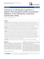
Figure 1.8
Principle of an HVDC transmission scheme
1.1.2 Direct-voltage systems
In effect a direct-voltage system is a hybrid circuit incorporating AC and DC
components (see Figure 1.8). The incoming power is from an alternating source,
which is rectified and filtered before transmission through the DC system, inversion
taking place at the receiving end in order to provide the usual AC supply conditions.
The harmonics produced by the converters are reduced by filters comprising R, L and
C elements. The earlier significant systems included that from the Swedish mainland
to Gotland (150 kV, 1954), the original cross-Channel connection between France
and England (± 100 kV, 1961), the crossing between the North and South Islands
of New Zealand (± 250 kV, 1965), the 50 Hz/60 Hz tie in Japan (125 kV, 1965), the
link between Sardinia and the Italian mainland (200 kV, 1967), the overhead line
from Volgograd to Donbass (± 400 kV, 1965) and the Pacific Intertie in the USA
(± 400 kV, 1970).
These groundbreaking systems (and a few others) incorporated mercury-arc technology, which tended to reduce the attraction of HVDC transmission due to various
operating problems. However, with the development of reliable high-voltage, highpower thyristors, the situation changed and there are now many systems worldwide.
Such schemes are well established, transmitting 60 GW or more of the world’s
power [6]. Typical voltage levels, powers transmitted and line lengths, together with
commissioning dates, are included in Table 1.1. The number of such schemes is
probably approaching one hundred.
Modern systems use two 6-pulse bridges giving a 12-pulse converter bridge.
One ‘valve’ consists of a number of thyristors – perhaps 100 series-connected units
for 600 kV, each of which may be rated at about 8.5 kV maximum peak voltage
withstand capability [7]. The number of thyristors required for 100 MW is quoted
as 18 (compared with 234 thirty years ago) in Reference 8. The complexity of these
structures has resulted in rigorous insulation testing procedures (see Section 7.11).
The advantages in respect of lower corona noise and losses, smaller wayleaves and
the capability of being able to utilize cables for long lengths because of the reduction
in losses compared with the three-phase AC equivalent may, in some applications,
www.EngineeringBooksPDF.com
9
Introduction
Table 1.1
Examples of HVDC transmission schemes: thyristor valves
System
Voltage
(kV)
Skagerrak
Vancouver
Nelson River BP2
Hokkaido Honshu
China
Itaipu BP
Cross Channel 2
USSR
Rihand–Dadri (Delhi)
E–W Malaysia
Garabi, Brazil
Three Gorges –
Changzhou, China
± 250
± 280
± 250
± 250
± 500
± 600
± 270
± 750
± 500
± 350
BtB Converters
± 500
Year
1976/77
1977/79
1975/85
1979/93
1987/98
1987
1986
1985
1991
1995
2000/2002
2003
Capacity
(MW)
OH line
(km)
Cable
(km)
500
476
2 000
600
1 200
3 000
1 000
1 500
1 500
1 000
2 200
3 000
113
41
930
124
1 100
783
–
2 400
840
–
127
33
–
44
–
–
72
–
–
600
offset the increased costs of converter stations compared with a corresponding AC
system. These features will, of course, also be advantageous where environmental
requirements are at a premium. The reliabilities of a significant number of the schemes
are monitored regularly by WG 14.04 of SC 14 of CIGRE [9]: this report covers 28
thyristor valve and 5 mercury-arc valve systems operating during 1997/1998. Data
were obtained initially in 1968.
Of special interest in respect of insulation assessment and possible monitoring
are the converter transformers, which may be subjected to combined alternating and
direct voltages, the smoothing reactors, the overhead line insulators, the bushings and
especially any cables/accessories, particularly as used for underwater crossings.
With the new systems utilizing voltage-sourced converters (see Subsection 1.4.4)
it appears that the insulation of equipment may be subjected to periodic impulse-type
voltages [8], the effects of which have not been extensively investigated.
1.2
Insulation coordination
Insulation coordination design of power systems aims at minimizing outages of major
items of plant and critical circuits caused by switching or lightning surges. The traditional protective methods use various forms of air gaps connected across particular
equipment or transmission-line components. Because of the lack of matching between
the V-T (volt-time) characteristics of the gaps and those of the non-restoring insulations in, for example, power transformers, the application may not be as effective
as required. Also the gaps may allow the passage of high-value power frequency
follow-through arcs.
www.EngineeringBooksPDF.com
10
Condition Assessment of High-Voltage Insulation
These limitations have been overcome to a large extent by the introduction of surge
arresters (see Chapters 4 and 7) incorporating nonlinear resistors. The units are more
complex than gaps, but have better response times and can suppress potential arcs. The
reliability of surge arresters has increased greatly, especially with the development
of the gapless type, which has raised confidence in their performance. Condition
monitoring under steady-state conditions is sometimes considered necessary.
In order to assist in the planning of insulation coordination of a power system,
international standards have been produced for determining appropriate insulation
levels in relation to the operating voltages. These levels are based on the expected
overvoltages that might be produced by the occasional power-frequency fault and
surges due to switching and lightning. During the detailed design of the power system,
estimates of such disturbances must be made. This is a very complex process, depending on many factors. Technical discussions and exchange of data have taken place over
many years through CIGRE and the IEC working groups, enabling agreed levels to be
set and making a major contribution to the design and construction of reliable and safe
systems [10, 11]. In the case of HVDC systems such standardization is not complete.
1.3
High-voltage test levels
The test voltages for power-frequency systems – short-duration and surge – standardized by the IEC for preferred values of Um – are listed in IEC 60071-1. It should be
noted that Um is the highest operating voltage classification of equipment (kV-RMS)
between phases, although the majority of tests are to ground. The basis for the choice
of the test levels and the associated voltage forms are discussed below.
The voltages chosen for a given level of Um will depend on local conditions, the
type of line, the method of protection adopted for surge suppression and any possible
pollution problems that might affect the power-frequency performance. The various
choices can be complex, requiring extensive analyses. Some guidance regarding the
concepts and procedures are given in the IEC documents 60071-2 and 60071-3 [10].
The situation for HVDC transmission systems is not well established and the
required test levels are determined by the user and manufacturer. IEC 60071-5 [11]
does not include preferred standardized levels. IEC publication 61378-2 covers the
application of converter transformers in HVDC supply systems [12].
A wide range of tests is applied to the individual components comprising the power
supply systems. The main proving high-voltage tests for new power-frequency equipment involve the application of overvoltages. These tests include power frequency,
lightning impulse and switching impulse depending on the chosen voltage class, as
indicated in Table 1.2. The values in relation to the operating voltages were chosen
following agreement within the industry based on long-term research and experience.
Tables are also available for wet tests with the different voltage forms.
The forms of the voltages that might exist in a power-frequency system are summarized in Table 1.3 together with possible test shapes where applicable. The relative
breakdown strengths of non-restoring insulation when subjected to different forms of
voltage are indicated in Figure 1.9 for a simple sample arrangement.
www.EngineeringBooksPDF.com
Introduction
Table 1.2
11
Possible test levels for particular system voltages. See IEC 60071-1 for
details and Table 1.3 for test voltage shapes
Highest system
voltage, Um
(phase–phase)
kV(RMS)
Short-duration power
frequency withstand
test voltage to earth
kV (RMS)
Lightning impulse
withstand test
voltage to earth
kV (peak)
28
70
140
230
395
95
170
325
650
1 050
12
36
72.5
145
245
Switching impulse withstand test voltages
300
362
420
525
765
Phase to earth
test voltage
kV peak
Phase to phase value
referred to phase to
earth test voltage
850
950
950
1 175
1 550
1.5
1.5
1.5
1.5
1.6
1 050
1 175
1 425
1 550
2 100
Extensive development testing and experience with prototypes contributed to the
choice of the relative test levels finally selected for equipment-proving tests – for
example as in Table 1.2. In addition, it is vital that the equipment insulation structures withstand the test voltages with an economically acceptable ‘safety factor’ (SF).
This factor may be simply defined as the estimated breakdown voltage ÷ specified
test voltage for each voltage form. The chosen value of SF allows for many conditions,
including complex insulation configurations, manufacturing variations, non-uniform
electric stress distributions and the natural (statistical) scatter in breakdown strength
of the materials of liquids, solid or gas/air. The choice of safety factors varies among
manufacturers and users and is a critical part of the design and manufacturing processes. As condition-monitoring techniques are improved for application during the
high-voltage test procedures, it may be possible to use lower SF values, thereby
resulting in a more economic product.
In practical equipment the ratio of the ‘one-minute’ test value to operating voltage
is as high as 2.8–3.5, for example transformers, bushings and switchgear. These
values have served the industry well and have ensured that equipment designed to
withstand such test levels will operate satisfactorily for 25 years or more, sustaining overvoltages caused by lightning, earth faults and some switching events. If a
www.EngineeringBooksPDF.com
12
Condition Assessment of High-Voltage Insulation
Table 1.3
Shape of AC and impulse test voltages
Class
Shape
Frequency and
time duration
(1) f = 50 or 60 Hz
(2) VLF, e.g. 0.1 Hz
(3) Resonance voltage
(20–300 Hz)
(4) Induced voltage tests
(100/120–400/480 Hz)
(5) Tt = 10 seconds to
60 minutes
AC tests
1/ f
Tt
1.0
Switching-impulse tests
Tp = 250 µs
T2 = 2500 µs
0.5
Tp
T2
1.0
0.9
Lightning-impulse tests
T1 = 1.2 µs
T2 = 50 µs
0.5
0.3
T1
Fast-impulse tests
T2
1/f2
1/f1
Tf
100 ns ≥ Tf > 3 ns
0.3 MHz < f1 < 100 MHz
30 kHz < f2 < 300 kHz
Tt ≤ 3 ms
Tt
high standard of maintenance and in-service monitoring is incorporated in the operational programmes, lives of 40 years are now being predicted. From Table 1.2 it
will be seen that for values of Um = 300 kV and above a short-time-duration powerfrequency test is not specified, a switching surge test (see Subsection 1.3.3) being
considered more appropriate. However, steady-state-test overvoltage proving tests
are retained in some form or other. In the case of transformers
this includes a par√
tial discharge test (see Chapter 7) at, perhaps, 1.5 × Um 3 for 60 minutes or more
for Um ≥ 300 kV units. In many cases such tests are called for on lower-voltage
equipment. The methods of producing the voltages for test purposes and procedures
www.EngineeringBooksPDF.com