Advanced gas turbine cycles
Bạn đang xem bản rút gọn của tài liệu. Xem và tải ngay bản đầy đủ của tài liệu tại đây (5.42 MB, 231 trang )
www.elsolucionario.net
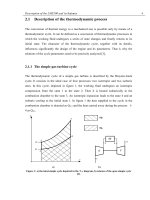
Corn bined STlG
Steam
-
Exhaust
4
Water
1i
li
q L
t
Air
PERGAMON
www.elsolucionario.net
Advanced Gas
Turbine Cycles
www.elsolucionario.net
www.elsolucionario.net
www.elsolucionario.net
www.elsolucionario.net
www.elsolucionario.net
www.elsolucionario.net
ADVANCED GAS TURBINE
CYCLES
www.elsolucionario.net
www.elsolucionario.net
www.elsolucionario.net
ADVANCED GAS TURBINE
CYCLES
Whittle Laboratory
Cambridge, U.K.
2003
An imprint of Elsevier Science
AMSTERDAM * BOSTON . HEIDELBERG . LONDON . NEW YORK
OXFORD . PARIS * S A N DEGO * SAN FRANCISCO SINGAPORE
SYDNEY . TOKYO
www.elsolucionario.net
J. H. Horlock F.R.Eng., F.R.S.
www.elsolucionario.net
ELSEVIER SCIENCE Ltd
The Boulevard, Langford Lane
Kidlington, Oxford OX5 lGB, UK
0 2003 Elsevier Science Ltd. All rights reserved.
This work is protected under copyright by Elsevier Science, and the following terms and conditions apply to its use:
Permissions may be sought directly from Elsevier’s Science & Technology Rights Department in Oxford, U K phone:
(4)
1865 843830, fax: (4)
1865 853333, e-mail: You may also complete your request
on-line via the Elsevier Science homepage (), by selecting ‘Customer Support’ and then
‘Obtaining Permissions’.
In the USA, users may clear permissions and make payments through the Copyright Clearance Center, Inc., 222
Rosewood Drive, Danvers, MA 01923, USA; phone: (+1) (978) 7508400, fax: 7504744, and in the UK through the
Copyright Licensing Agency Rapid Clearance Service (CLARCS), 90 Tottenham Court Road, London W1P OLP, U K
207 631 5555; fax: (4)
207 631 5500. Other countries may have a local reprographic rights agency for
phone: (4)
payments.
Derivative Works
Tables of contents may be reproduced for internal circulation,but permission of Elsevier Science is required for external
resale or distribution of such material.
Permission of the Publisher is required for all other derivative works, including compilations and translations.
Electronic Storage or Usage
Permission of the Publisher is required to store or use electronically any material contained in this work, including any
chapter or part of a chapter.
Except as outlined above, no part of this work may be reproduced, stored in a retrieval system or transmitted in any form
or by any means, electronic, mechanical, photocopying, recording or otherwise, without prior written permission of the
Publisher.
Address permissions requests to: Elsevier’s Science & Technology Rights Department, at the phone, fax and e-mail
addresses noted above.
Notice
No responsibility is assumed by the Publisher for any injury andor damage to persons or property as a matter of products
liability, negligence or otherwise, or from any use or operation of any methods, products, instructionsor ideas contained
in the material herein. Because of rapid advances in the medical sciences, in particular, independent verification of
diagnoses and drug dosages should be made.
First edition 2003
Library of Congress Cataloging in Publication Data
A catalog record from the Library of Congress has been applied for.
British Library Cataloguing in Publication Data
A catalogue record from the British Library has been applied for.
ISBN 0-08-044273-0
@ The paper used in this publication meets the requirements of ANSI/NISO 239.48-1992 (Permanence of Paper).
Printed in The Netherlands
www.elsolucionario.net
Photocopying
Single photocopies of single chapters may be made for personal use as allowed by national copyright laws. Permission of
the Publisher and payment of a fee is required for all other photocopying, including multiple or systematic copying,
copying for advertising or promotional purposes, resale, and all forms of document delivery. Special rates are available
for educational institutions that wish to make photocopies for non-profit educational classroom use.
www.elsolucionario.net
www.elsolucionario.net
To W.R.H.
www.elsolucionario.net
www.elsolucionario.net
www.elsolucionario.net
.
xiii
xvii
Chapter 1
A brief review of power generation thermodynamics. . . . .
1
1.1.
1.2.
1.2.1.
1.2.2.
1.2.3.
1.2.4.
1.3.
1.4.
1.5.
Introduction . . . . . . . . . . . . . . . . . . . . . . . . . . . . . . . . . .
Criteria for the performance of power plants . . . . . . . . . . . .
Efficiency of a closed circuit gas turbine plant . . . . . . . . . . .
Efficiency of an open circuit gas turbine plant . . . . . . . . . . .
Heatrate . . . . . . . . . . . . . . . . . . . . . . . . . . . . . . . . . . . .
Energy utilisation factor . . . . . . . . . . . . . . . . . . . . . . . . . .
Ideal (Carnot) power plant performance . . . . . . . . . . . . . . .
Limitations of other cycles ........................
Modifications of gas turbine cycles to achieve higher
thermalefficiency . . . . . . . . . . . . . . . . . . . . . . . . . . . . . .
References . . . . . . . . . . . . . . . . . . . . . . . . . . . . . . . . . . .
9
11
Chapter 2
Reversibility and availability......................
13
2.1.
2.2.
2.2.1.
Introduction ..................................
Reversibility. availability and exergy . . . . . . . . . . . . . . . . .
Flow in the presence of an environment at To (not
involving chemical reaction) .......................
Flow with heat transfer at temperature T . . . . . . . . . . . . . . .
Exergy flux . . . . . . . . . . . . . . . . . . . . . . . . . . . . . . . . . . .
Application of the exergy flux equation to a closed cycle . . . .
The relationships between 6. (+and ZCR. Z Q . . . . . . . . . . . . .
The maximum work output in a chemical reaction at To. . . . .
The adiabatic combustion process....................
The work output and rational efficiency of an open circuit
gas turbine . . . . . . . . . . . . . . . . . . . . . . . . . . . . . . . . . . .
A final comment on the use of exergy . . . . . . . . . . . . . . . . .
References . . . . . . . . . . . . . . . . . . . . . . . . . . . . . . . . . . .
13
14
.
2.2.2.
2.3.
2.3.1.
2.3.2.
2.4.
2.5.
2.6.
2.7.
14
16
19
20
20
22
23
24
26
26
.........................
27
..................................
27
Chapter 3
Basic gas turbine cycles
3.1.
Introduction
vii
www.elsolucionario.net
Preface . . . . . . . . . . . . . . . . . . . . . . . . . . . . . . . . . . . . . . . . . . . . . . . . .
Notation . . . . . . . . . . . . . . . . . . . . . . . . . . . . . . . . . . . . . . . . . . . . . . . .
www.elsolucionario.net
3.2.
3.2.1.
3.2.1.1.
3.2.1.2.
3.2.1.3.
3.2.1.4.
3.2.1.5.
3.2.2.
3.2.2.1.
3.2.2.2.
3.2.2.3.
3.2.3.
3.3.
3.4.
3.4.1.
3.4.2.
3.5.
.
Chapter 4
4.1.
4.2.
4.2.1.
4.2,l.l.
4.2.1.2.
4.2.1.3.
4.2.1.4.
4.2.2.
4.2.2.1.
4.2.2.2.
4.2.2.3.
4.2.2.4.
4.2.2.5.
4.3.
4.3.1.
4.3.2.
4.3.2.1.
4.3.2.2.
4.3.3.
Air standard cycles (uncooled) . . . . . . . . . . . . . . . . . . . . . .
Reversible cycles . . . . . . . . . . . . . . . . . . . . . . . . . . . . . . .
The reversible simple (Joule-Brayton) cycle. [CHTIR. . . . . . .
The reversible recuperative cycle [ C m ] R . . . . . . . . . . . . . .
The reversible reheat cycle [CHTHTIR. . . . . . . . . . . . . . . . .
The reversible intercooled cycle [CICHTIR . . . . . . . . . . . . . .
The 'ultimate' gas turbine cycle .....................
Irreversible air standard cycles ......................
Component performance . . . . . . . . . . . . . . . . . . . . . . . . . .
The irreversible simple cycle [CHTII . . . . . . . . . . . . . . . . . .
The irreversible recuperative cycle [CHTXII . . . . . . . . . . . . .
Discussion . . . . . . . . . . . . . . . . . . . . . . . . . . . . . . . . . . . .
The [CBTII open circuit plant-a general approach . . . . . . . .
Computer calculations for open circuit gas turbines . . . . . . . .
The [CBTIIGplant ...............................
Comparison of several types of gas turbine plants. . . . . . . . . .
Discussion . . . . . . . . . . . . . . . . . . . . . . . . . . . . . . . . . . . .
References . . . . . . . . . . . . . . . . . . . . . . . . . . . . . . . . . . . .
28
28
28
29
30
32
32
33
33
34
37
39
39
43
43
44
45
46
Cycle efficiency with turbine cooling (cooling flow
ratesspecified). . . . . . . . . . . . . . . . . . . . . . . . . . . . . . . . .
47
Introduction . . . . . . . . . . . . . . . . . . . . . . . . . . . . . . . . . . .
Air-standard cooled cycles . . . . . . . . . . . . . . . . . . . . . . . . .
Cooling of internally reversible cycles . . . . . . . . . . . . . . . . .
Cycle [CHTIRCIwith single step cooling . . . . . . . . . . . . . . .
Cycle [cHT]RC* with two step cooling . . . . . . . . . . . . . . . . .
Cycle [cHT]Rm with multi-step cooling . . . . . . . . . . . . . . .
The turbine exit condition (for reversible cooled cycles) . . . . .
Cooling of irreversible cycles . . . . . . . . . . . . . . . . . . . . . . .
Cycle with single-step cooling [CH'I'IIcl . . . . . . . . . . . . . . . .
Efficiency as a function of combustion temperature or
rotor inlet temperature (for single-step cooling) . . . . . . . . . . .
Cycle with two step cooling [CHTIIa . . . . . . . . . . . . . . . . .
Cycle with multi-step cooling [CHTlICM. . . . . . . . . . . . . . . .
Comment . . . . . . . . . . . . . . . . . . . . . . . . . . . . . . . . . . . . .
Open cooling of turbine blade rows-detailed fluid
mechanics and thermodynamics......................
Introduction . . . . . . . . . . . . . . . . . . . . . . . . . . . . . . . . . . .
The simple approach . . . . . . . . . . . . . . . . . . . . . . . . . . . . .
Change in stagnation enthalpy (or temperature) through
an open cooled blade row . . . . . . . . . . . . . . . . . . . . . . . . . .
Change of total pressure through an open cooled blade row . . .
Breakdown of losses in the cooling process . . . . . . . . . . . . . .
47
48
49
49
51
52
54
55
55
56
58
59
59
59
59
61
61
62
64
www.elsolucionario.net
Confenrs
viii
www.elsolucionario.net
Contents
ix
.
65
68
69
Chapter 5
Full calculations of plant efficiency
.................
71
5.1.
5.2.
5.2.1.
5.2.2.
5.2.3.
5.3.
5.4.
5.5.
5.6.
5.7.
5.8.
5.9.
Introduction . . . . . . . . . . . . . . . . . . . . . . . . . . . . . . . . . .
Cooling flow requirements ........................
Convective cooling .............................
Film cooling . . . . . . . . . . . . . . . . . . . . . . . . . . . . . . . . . .
Assumptions for cycle calculations . . . . . . . . . . . . . . . . . . .
Estimates of cooling flow fraction . . . . . . . . . . . . . . . . . . .
Single step cooling .............................
Multi-stage cooling .............................
A note on real gas effects .........................
Other studies of gas turbine plants with turbine cooling . . . . .
Exergy calculations . . . . . . . . . . . . . . . . . . . . . . . . . . . . .
Conclusions . . . . . . . . . . . . . . . . . . . . . . . . . . . . . . . . . .
References . . . . . . . . . . . . . . . . . . . . . . . . . . . . . . . . . . .
71
71
71
72
73
73
75
75
82
82
82
84
84
Chapter 6
‘Wet’ gas turbine plants . . . . . . . . . . . . . . . . . . . . . . . . .
85
6.1.
6.2.
6.2.1.
6.2.2.
6.3.
6.3.1.
Introduction . . . . . . . . . . . . . . . . . . . . . . . . . . . . . . . . . .
Simple analyses of STIG type plants . . . . . . . . . . . . . . . . . .
The basic STIG plant ............................
The recuperative STIG plant . . . . . . . . . . . . . . . . . . . . . . .
Simple analyses of EGT type plants . . . . . . . . . . . . . . . . . .
A discussion of dry recuperative plants with ideal heat
exchangers . . . . . . . . . . . . . . . . . . . . . . . . . . . . . . . . . . .
The simple EGT plant with water injection . . . . . . . . . . . . .
Recent developments . . . . . . . . . . . . . . . . . . . . . . . . . . . .
Developments of the STIG cycle ....................
The ISTIG cycle . . . . . . . . . . . . . . . . . . . . . . . . . . . . . . .
The combined STIG cycle.........................
The FAST cycle . . . . . . . . . . . . . . . . . . . . . . . . . . . . . . .
Developments of the EGT cycle .....................
The RWI cycle . . . . . . . . . . . . . . . . . . . . . . . . . . . . . . . .
The HAT cycle . . . . . . . . . . . . . . . . . . . . . . . . . . . . . . . .
The REVAP cycle ..............................
The CHAT cycle ...............................
The TOPHAT cycle .............................
Simpler direct water injection cycles . . . . . . . . . . . . . . . . . .
85
85
85
90
91
.
6.3.2.
6.4.
6.4.1.
6.4.1 .1.
6.4.1.2.
6.4.1.3.
6.4.2.
6.4.2.1.
6.4.2.2.
6.4.2.3.
6.4.2.4.
6.4.2.5.
6.4.3.
91
93
97
97
97
99
99
99
100
100
100
101
101
103
www.elsolucionario.net
Cycle calculations with turbine cooling . . . . . . . . . . . . . . . .
Conclusions . . . . . . . . . . . . . . . . . . . . . . . . . . . . . . . . . .
References . . . . . . . . . . . . . . . . . . . . . . . . . . . . . . . . . . .
4.4.
4.5.
www.elsolucionario.net
6.5.
A discussion of the basic thermodynamics of
these developments . . . . . . . . . . . . . . . . . . . . . . . . . . . . . .
Some detailed parametric studies of wet cycles . . . . . . . . . . .
Conclusions . . . . . . . . . . . . . . . . . . . . . . . . . . . . . . . . . . .
References . . . . . . . . . . . . . . . . . . . . . . . . . . . . . . . . . . . .
103
105
107
107
Chapter 7
The combined cycle gas turbine (CCGT) . . . . . . . . . . . . . .
109
7.1.
7.2.
7.3.
Introduction . . . . . . . . . . . . . . . . . . . . . . . . . . . . . . . . . . .
An ideal combination of cyclic plants . . . . . . . . . . . . . . . . . .
A combined plant with heat loss between two cyclic
plants in series . . . . . . . . . . . . . . . . . . . . . . . . . . . . . . . . .
The combined cycle gas turbine plant (QCGT) . . . . . . . . . . . .
The exhaust heated (unfired) CCGT . . . . . . . . . . . . . . . . . . .
The integrated coal gasification combined
cycle plant (IGCC) . . . . . . . . . . . . . . . . . . . . . . . . . . . . . .
The exhaust heated (supplementary fired) CCGT . . . . . . . . . .
The efficiency of an exhaust heated CCGT plant . . . . . . . . . .
A parametric calculation . . . . . . . . . . . . . . . . . . . . . . . . . .
Regenerative feed heating . . . . . . . . . . . . . . . . . . . . . . . . . .
The optimum pressure ratio for a CCGT plant . . . . . . . . . . . .
Reheating in the upper gas turbine cycle . . . . . . . . . . . . . . . .
Discussion and conclusions.........................
References . . . . . . . . . . . . . . . . . . . . . . . . . . . . . . . . . . . .
109
109
Chapter 8
Novel gas turbine cycles . . . . . . . . . . . . . . . . . . . . . . . . . .
131
8.1.
8.2.
8.2.1.
Introduction . . . . . . . . . . . . . . . . . . . . . . . . . . . . . . . . . . .
Classification of gas-fired plants using novel cycles . . . . . . . .
Plants (A) with addition of equipment to remove the carbon
dioxide produced in combustion . . . . . . . . . . . . . . . . . . . . .
Plants (B) with modification of the fuel in
combustion-chemically reformed gas turbine
(CRGT) cycles . . . . . . . . . . . . . . . . . . . . . . . . . . . . . . . . .
Plants (C) using non-carbon fuel (hydrogen) . . . . . . . . . . . . .
Plants (D) with modification of the oxidant in combustion . . . .
Outline of discussion of novel cycles . . . . . . . . . . . . . . . . . .
COz removal equipment . . . . . . . . . . . . . . . . . . . . . . . . . . .
The chemical absorption process . . . . . . . . . . . . . . . . . . . . .
The physical absorption process .....................
Semi-closure . . . . . . . . . . . . . . . . . . . . . . . . . . . . . . . . . .
The chemical reactions involved in various cycles . . . . . . . . .
Complete combustion in a conventional open circuit plant . . . .
Thermo-chemical recuperation using steam (steam.TCR) . . . . .
Partial oxidation . . . . . . . . . . . . . . . . . . . . . . . . . . . . . . . .
131
132
132
6.6.
6.7.
.
7.4.
7.4.1.
7.4.2.
7.4.3.
7.5.
7.5.1.
7.5.2.
7.6.
7.7.
7.8.
.
8.2.2.
8.2.3.
8.2.4.
8.2.5.
8.3.
8.3.1.
8.3.2.
8.4.
8.5.
8.5.1.
8.5.2.
8.5.3.
110
111
112
114
116
117
118
122
123
126
128
129
133
133
135
135
136
136
136
139
140
140
141
143
www.elsolucionario.net
Contents
X
www.elsolucionario.net
8.5.4.
Thermo-chemical recuperation using flue gases
(fluegas/TCR) . . . . . . . . . . . . . . . . . . . . . . . . . . . . . . . .
Combustion with recycled flue gas as a carrier . . . . . . . . . . .
Descriptions of cycles ...........................
Cycles A with additional removal equipment for carbon
dioxide sequestration . . . . . . . . . . . . . . . . . . . . . . . . . . . .
Direct removal of COz from an existing plant . . . . . . . . . . .
Modifications of the cycles of conventional plants using the
semi-closed gas turbine cycle concept . . . . . . . . . . . . . . . . .
Cycles B with modification of the fuel in combustion
through thenno-chemical recuperation (TCR) . . . . . . . . . . . .
The steam/TCR cycle . . . . . . . . . . . . . . . . . . . . . . . . . . . .
The flue gas thermo-chemically recuperated (FG/TCR) cycle .
Cycles C burning non-carbon fuel (hydrogen) . . . . . . . . . . .
Cycles D with modification of the oxidant in combustion . . . .
Partial oxidation cycles...........................
Plants with combustion modification (full oxidation) . . . . . . .
IGCC cycles with C02 removal (Cycles E) . . . . . . . . . . . . .
Summary . . . . . . . . . . . . . . . . . . . . . . . . . . . . . . . . . . . .
References . . . . . . . . . . . . . . . . . . . . . . . . . . . . . . . . . . .
8.5.5.
8.6.
8.6.1.
8.6.1.1.
8.6.1.2.
8.6.2.
8.6.2.1.
8.6.2.2.
8.6.3.
8.6.4.
8.6.4.1.
8.6.4.2.
8.7.
8.8.
.
xi
143
144
144
144
144
146
147
149
150
152
154
155
158
160
162
164
CHAPTER 9
The gas turbine as a cogeneration
(combined heat and power) plant. . . . . . . . . . . . . . . . . . .
167
9.1.
9.2.
9.2.1.
9.2.2.
9.2.3.
9.3.
9.4.
9.5.
9.6.
9.6.1.
9.6.2.
Introduction . . . . . . . . . . . . . . . . . . . . . . . . . . . . . . . . . .
Performance criteria for CHP plants . . . . . . . . . . . . . . . . . .
Energy utilisation factor ..........................
Artificial thermal efficiency ........................
Fuel energy saving ratio ..........................
The unmatched gas turbine CHP plant . . . . . . . . . . . . . . . .
Range of operation for a gas turbine CHP plant . . . . . . . . . .
Design of gas turbines as cogeneration (CHP) plants . . . . . . .
Some practical gas turbine cogeneration plants . . . . . . . . . . .
The Beilen CHP plant . . . . . . . . . . . . . . . . . . . . . . . . . . .
The Liverpool University CHP plant . . . . . . . . . . . . . . . . . .
References . . . . . . . . . . . . . . . . . . . . . . . . . . . . . . . . . . .
167
168
168
170
170
173
174
177
177
177
180
181
.
APPENDIX A Derivation of required cooling flows. . . . . . . . . . . . . . . . .
A.l.
A.2.
A.3.
A.4.
Introduction . . . . . . . . . . . . . . . . . . . . . . . . . . . . . . . . . .
Convective cooling only ..........................
Film cooling . . . . . . . . . . . . . . . . . . . . . . . . . . . . . . . . . .
The cooling efficiency ...........................
183
183
183
185
186
www.elsolucionario.net
Contents
www.elsolucionario.net
contmrs
A S.
.
Summary . . . . . . . . . . . . . . . . . . . . . . . . . . . . . . . . . . . . .
References . . . . . . . . . . . . . . . . . . . . . . . . . . . . . . . . . . . .
186
187
....................
189
APPENDIX B Economics of gas turbine plants
B.I.
B.2.
B.3.
B.4.
B.5.
Index
Introduction . . . . . . . . . . . . . . . . . . . . . . . . . . . . . . . . . . .
Electricity pricing . . . . . . . . . . . . . . . . . . . . . . . . . . . . . . .
The capital charge factor . . . . . . . . . . . . . . . . . . . . . . . . . .
Examples of electricity pricing . . . . . . . . . . . . . . . . . . . . . .
Carbon dioxide production and the effects of a carbon tax . . . .
References . . . . . . . . . . . . . . . . . . . . . . . . . . . . . . . . . . . .
...................................................
189
189
190
191
192
194
195
www.elsolucionario.net
xii
www.elsolucionario.net
Many people have described the genius of von Ohain in Germany and Whittle in the
United Kingdom, in their parallel inventions of gas turbine jet propulsion; each developed
an engine through to first flight. The best account of Whittle’s work is his Clayton lecture
of 1946 [l]; von Ohain described his work later in [2]. Their major invention was the
turbojet engine, rather than the gas turbine, which they both adopted for their new
propulsion engines.
Feilden and Hawthorne [3] describe Whittle’s early thinking in their excellent
biographical memoir on Whittle for the Royal Society.
“‘I‘he idea for the turbojet did not come to Whittle suddenly, but over a period
of some years: initially while he was a final year flight cadet at RAF Cranwell
about 1928; subsequently as a pilot officer in a fighter squadron; and then
finally while he was a pupil on a flying instructor’s course.. .. While involved
in these duties Whittle continued to think about his ideas for high-speed high
altitude flight. One scheme he considered was using a piston engine to drive a
blower to produce a jet. He included the possibility of burning extra fuel in the
jet pipe but finally had the idea of a gas turbine producing a propelling jet
instead of driving a propeller”.
But the idea of gas turbine itself can be traced back to a 1791 patent by Barber, who
wrote of the basic concept of a heat engine for power generation. Air and gas were to be
compressed and burned to produce combustion products; these were to be used to drive a
turbine producing a work output. The compressor could be driven independently (along
the lines of Whittle’s early thoughts) or by the turbine itself if it was producing enough
work.
Here lies the crux of the major problem in the early development of the gas turbine. The
compressor must be highly efficient-it must use the minimum power to compress the gas;
the turbine must also be highly efficient-it must deliver the maximum power if it is to
drive the compressor and have power over. With low compressor and turbine efficiency,
the plant can only just be self-sustaining-the turbine can drive the compressor but do no
more than that.
Stodola in his great book of 1925 [4] describes several gas turbines for power
generation, and Whittle spent much time studying this work carefully. Stodola tells how in
1904, two French engineers, Armengaud and Lemae, built one of the first gas turbines, but
it did little more than turn itself over. It appears they used some steam injection and the
small work output produced extra compressed air-but not much. The overall efficiency
has been estimated at 2-3% and the effective work output at 6- 10kW.
Much later, after several years of development (see Eckardt and Rufli [ 5 ] ) ,
Brown Boveri produced the first industrial gas turbine in 1939, with an electrical power
xiii
www.elsolucionario.net
PREFACE
www.elsolucionario.net
Prefwe
output of 4MW. Here the objective of the engineering designer was to develop as much
power as possible in the turbine, discharging the final gas at low temperature and velocity;
as opposed to the objective in the Whittle patent of 1930, in which any excess energy in the
gases at exhaust from the gas generator-the turbine driving the compressor-would be
used to produce a high-speed jet capable of propelling an aircraft.
It was the wartime work on the turbojet which provided a new stimulus to the further
development of the gas turbine for electric power generation, when many of the aircraft
engineers involved in the turbojet work moved over to heavy gas turbine design. But
surprisingly it was to be the late twentieth century before the gas turbine became a major
force in electrical generation through the big CCGTs (combined cycle gas turbines, using
bottoming steam cycles).
This book describes the thermodynamics of gas turbine cycles (although it does touch
briefly on the economics of electrical power generation). The strictures of classical
thermodynamics require that “cycle” is used only for a heat engine operating in closed
form, but the word has come to cover “open circuit” gas turbine plants, receiving “heat”
supplied through burning fuel, and eventually discharging the products to the atmosphere
(including crucially the carbon dioxide produced in combustion). The search for high gas
turbine efficiency has produced many suggestions for variations on the simple “open
circuit” plant suggested by Barber, but more recently work has been directed towards gas
turbines which produce less COz, or at least plants from which the carbon dioxide can be
disposed of, subsequent to sequestration.
There are many books on gas turbine theory and performance, notably by Hodge [6],
Cohen, Rogers and Saravanamuttoo[7], Kerrebrock [8], and more recently by Walsh and
Fletcher [9]; I myself have added two books on combined heat and power and on
combined power plants respectively [10,11]. They all range more widely than the basic
thermodynamics of gas turbine cycles, and the recent flurry of activity in this field has
encouraged me to devote this volume to cycles alone. But the remaining breadth of gas
turbine cycles proposed for power generation has led me to exclude from this volume the
coupling of the gas turbine with propulsion. I was also influenced in this decision by the
existence of several good books on aircraft propulsion, notably by Zucrow [12], Hill and
Peterson [13]; and more recently my friend Dr Nicholas Cumpsty, Chief Technologist of
Rolls Royce, plc, has written an excellent book on “Jet Propulsion” [ 141.
I first became interested in the subject of cycles when I went on sabbatical leave to
MIT,from Cambridge England to Cambridge Mass.There I was asked by the Director of
the Gas Turbine Laboratory, Professor E.S.Taylor, to take over his class on gas turbine
cycles for the year. The established text for this course consisted of a beautiful set of
notes on cycles by Professor (Sir) William Hawthorne, who had been a member of
Whittle’s team.Hawthorne’s notes remain the best starting point for the subject and I
have called upon them here, particularly in the early part of Chapter 3.
Hawthorne taught me the power of temperature-entropy diagram in the study of cycles,
particularly in his discussion of “air standard” cycles-assuming the working fluid to be a
perfect gas, with constant specific heats. It is interesting that Whittle wrote in his later
book [15] that he himself “never found the (T,s diagram) to be useful”, although he had a
profound understanding of the basic thermodynamics of gas turbine cycles. For he also
wrote
www.elsolucionario.net
xiv
www.elsolucionario.net
xv
“When in jet engine design, greater accuracy was necessary for detail design, I worked
in pressure ratios, used y = 1.4 for compression and y = 1.3 for expansion and assumed
specific heats for combustion and expansion corresponding to the temperature range
concerned. I also allowed for the increase in mass flow in expansion due to fuel addition
(in the range 1.5-2%). The results, despite guesswork involved in many of the
assumptions, amply justified these methods to the point where I was once rash enough to
declare that jet engine design has become an exact science”. Whittle’s modifications of air
standard cycle analysis are developed further in the later parts of Chapter 3.
Hawthorne eventually wrote up his MIT notes for a paper with his research student,
Graham de Vahl Davis [ 161, but it is really Will Hawthorne who should have written this
book. So I dedicate it to him, one of several great engineering teachers, including Keenan,
Taylor and Shapiro, who graced the mechanical engineering department at MIT when I
was there as a young assistant professor.
My subsequent interest in gas turbines has come mainly from a happy consulting
arrangement with Rolls Royce, plc and the many excellent engineers I have worked with
there, including particularly Messrs.Wilde, Scrivener, Miller, Hill and Ruffles. The
Company remains at the forefront of gas turbine engineering.
I must express my appreciation to many colleagues in the Whittle Laboratory of the
Engineering Department at Cambridge University. In particular I am grateful to Professor
John Young who readily made available to me his computer code for “real gas” cycle
calculations; and to Professors Cumpsty and Denton for their kindness in extending to me
the hospitality of the Whittle Laboratory after I retired as Vice-Chancellor of the Open
University. It is a stimulating academic environment.
I am also indebted to many friends who have read chapters in this book including John
Young, Roger Wilcock, Eric Curtis, Alex White (all of the Cambridge Engineeering
Department), Abhijit Guha (of Bristol University), Pericles Pilidis (of Cranfield
University) and Giampaolo Manfrida (of Florence University). They have made many
suggestions and pointed out several errors, but the responsibility for any remaining
mistakes must be mine.
Mrs Lorraine Baker has helped me greatly with accurate typing of several of the
chapters, and my friend John Stafford, of Compu-Doc (silsoe-solutions) has provided
invaluable help in keeping my computer operational and giving me many tips on preparing
the material. My publishing editor, Keith Lambert has been both helpful and encouraging.
Finally I must thank my wife Sheila, for putting up with my enforced isolation once
again to write yet another book.
J. H. Horlock
Cambridge, June 2002
REFERENCES
[l] Whittle, Sir Frank. (1945). The early history of the Whittle jet propulsion engine, Proc. Inst. Mech. Engrs.
152,419-435.
[2] von Ohain, H. (1979), The Evolution and Future of Aero-propulsion Systems. 40 Years of Jet Engine
Rogress. W.J. Boyne, and D.S. Lopez, (ed.), National Air and Space Museum, Washington DC.
www.elsolucionario.net
Preface
www.elsolucionario.net
Preface
[31 Feilden, G.B.R. and Hawthome, W.R., Sir Frank Whittle, O.M. K.B.E. (1998) Biological Memoirs of the
Royal Society, 435-452.
[4] Stodola, A. (1924). Steam and Gas Turbines. McGraw Hill, New Yo&.
[51 Eckardt, D. and Rufli,P. (2000). ABBlBBC Gas Turbines - A Record of Historic Firsts, ASME Turbo-Expo
2000 Paper TE00 A10.
[61 Hodge, J. (1955), Cycles and performance Estimation. Buttenvaths, London.
[71 Cohen, H., Rogers, G.F.C. and Saravanamuttoo,H.I.H. (1996). Gas Turbine Theory. Longman, 4th edn.
[8] Kerrebrock, J. (1992). Aircraft Engines and Gas Turbines. MlT Press.
[9] Walsh, P.P. and Fletcher, P. (1998). Gas Turbine Performance. Blackwell Science, Oxford.
[lo] Horlock, J.H. (1987), Cogeneration - Combined Heat and Power Plants. Pergamon, 2nd edn, Krieger,
Malabar, Florida, 1997.
[ l l ] Horlock, J.H. (1992), Combined Power Plants. Pergamon, 2nd edn,Krieger, Melbourne, USA, 2002.
[12] Zucrow, M.J. (1958). Aircraft and Missile Propulsion John Wiley, New York.
[131 Hill, P.G. and Peterson, C.R. (1992). Mechanics and Thermodynamics of Propulsion. MIT Press, 2nd edn.
[14] Cumpsty, N.A. (1997), Jet Propulsion. Cambridge University Press.
[151 Whittle, Sir Frank. (1981). Gas Turbine Aero-Themodynamics. Pergamon Press, Oxford.
[16] Hawthorne. W. R.,and Davis, G. de V.(1956). Calculating gas turbine performance. Engng. 181,361-367.
The author is grateful to the following for permission to reproduce the figures listed below.
Pergamon Press, Oxford, UK Figs. 1.2, 1.3, 9.7 and 9.8
Krieger Publishing Company, Melbourne, Florida, USA Figs. 1.4, 1.7, 1.8, 2.1, 2.2, 2.3,
2.4, 2.5, 7.3, 7.5, 7.6, 9.5.
American Society of Mechanical Engineers: Figs. 4.1, 4.2, 4.3, 4.4, 4.5, 4.6, 4.7, 4.11,
4.12,5.4,5.6,5.9,5.10,5.11,6.1,6.8,6.9,6.10,6.12,6.14,6.18,6.19,6.20,7.4,7.7,7.11,
8.1, 8.2, 8.6, 8.7, 8.13, 8.14, 8.16, 8.17, 8.18, 8.19, 8.20, 8.24, 8.25, 8.26, 8.27, 8.28,A.1,
B.l, B.2, B.3.
Council of the Institution of Mechanical Engineers: Figs. 3.8, B.4, 7.9, 7.10.
Princeton University: Figs. 6.2,6.3, 6.4, 8.11, 8.12.
Pearson Education Limited Fig. 3.12.
Brown Boveri Company Ltd, Baden, Switzerland: Fig. 7.8.
International Journal of Applied Thermodynamics: Figs. 8.8, 8.23
www.elsolucionario.net
Xvi
www.elsolucionario.net
NOTATION
Note: Lower case symbols for propertiesrepresent specific quantities (Le. per unit mass)
Meaning
A
b, B
B
C
area
CP
rcv10
dh
e, E
I
8
EUF
f
F
g. G
irH
h
H
1
I
rcR
P
L
rn
M
RR'
NDCW
NDTW
NDNW
NDHT
N
OM
P
P
8.
Q
r
R
R
S
s,
s
st
t
T
V
w, w
Typical Units
steady flow availability
Biot number
capital cost
specific heat capacity, at constant pressure
calorific value at temperature To
hydraulic diameter
e x w
work potential of heat transferred thennal exery
energy utilisation factor
fuellair ratio; also friction factor
fuel energy supplied
Gibbs function
enthalpy
heat transfer coefficient
plant utilisation
interest or discount rate
lost work due to irreversibility (total)
lost work due to internal irreversibility
lost work due to heat transfer to the atmosphere
blade length
mass fraction (e.g. of main steam flow)
Mass flow; also fuel cost per annum;also
molecular weight: also Mach number
Ratio of air and gas specific heats, ( c d ( c m )
non-dimensional compressor work
non-dimensional hnbine work
non-dimensional net work
non-dimensional heat supplied
plant life
annual operational maintenance costs
pressure
electricity cost per year
heat supplied or rejected
pressure ratio
gas constant
universal gas constant
fuel costs per unit mass;also steam to air ratio
entropy
Stanton number
time; also thermal barrier thickness
temperature
velocity
specific work output, work output
xvii
www.elsolucionario.net
Symbol
www.elsolucionario.net
xviii
Notation
(continued)
w+,
w+
X
Y
z
A, B,
C,D. E,
F, KK'
a
a
Typical Units
Meaning
temperature difference ratios in heat transfer
isentropic t e m p h u t ratio
velocity ratio
polytropic expansion index
constants defined in text
B
proportions of capital cost
= %lh@
= I + % (8 - 1); also capital cost factor
Y
= C*/C"
6
loss parameter
heat exchanger effectiveness; also quantity
defined in eqn. [4.24]
cost of fuel per unit of energy
efficiency - see note below
ratio of maximum to minimum temperahut
area ratio in heat transfer; also CO,
performance parameter
scaling factor on steam entropy, ratio of mass flows in
combined cycle (lower to upper)
nondimensional heat supplied (v,) or heat unused (w)
parameters in cycle analysis
density
T ~ J T - ; also corporate tax rate
cooling air mass flow fraction
temperature function, J:
also turbine stage loading coefficient
expansion index defined in text
constant in expression for stagnation pressure loss
E
b
t
8
A
CL
Y
14Efl.T
P
*4
7
U
K
9,
subsrripts
4 a', b, b', c,
d, e, e', f, f'
a
A
bl
B
C
cot
C
CAR
cc
CP
CG
cs
cv
d
dP
states in steam cycle
air
relating to heat rejection; artificial efficiency
blade (temperature)
boiler; relating to heat supply
cooling air
combustion (temperature)
compressor (isentropic efficiency)
Carnot cycle
combustion chamber (efficiency or loss)
combined plant (general)
cogeneration plant
control surface
control volume
debt
dewpoint
i-1
(-f
www.elsolucionario.net
Symbol
www.elsolucionario.net
xix
Notation
(continued)
Meaning
D
e
E
demand
maximum efficiency; also equity; also external
electrical (unit price); also exit from turbine, and
from first turbine stage
fuel
gas
higher (upper, topping), relating to heat supply,
work output
between high and lower plants
rejection from higher plant
Joule-Brayton cycle
inlet
irreversible Joule-Brayton cycle
product gas component; also year number (k= 1,2, . . . )
lower (bottoming), relating to heat supply, work output
rejection from lower plant
maximum
minimum
mixture
non-useful (heat rejection)
outlet
overall (efficiency)
polytropic (efficiency)
product of combustion
product of supplementary combustion
rotor inlet temperature
rational; also reactants
reversible (process)
steam; also state after isentropic compression or
expansion; also surface area (A,)
state at entry to stack also supplementary heating
turbine (isentropic efficiency)
useful (heat delivered)
water; also maximum specific work
cross-sectional flow area (Ax)
states leaving heat exchanger; also states at entry
and exit from component
miscellaneous, refemng to gas states
HL
HR
JB
i
LIB
k
L
LR
rnax
min
m
Nu
0
0
P
P
p'
rit
R
REV
S
S
T
U
W
X
x. Y
1, I/, 2, 2'.
3, 3/, 4,4', . . . .
0
superscripts
CR
Q
Typical Units
www.elsolucionario.net
Symbol
conceptual environment (ambient state);
also stagnation pressure
refemng to internal irreversibility
refemng to thermal exergy
(associated with heat transfer); also to
lost work due to external irreversibility associated
with heat transfer
rate of (mass flow, heat supply, work output, etc)
new or changed value (e.g. of efficiency)
(continued on next pnge)
www.elsolucionario.net
Notation
xx
(continued)
Meaning
’ (e.g. a’, b’, 1’.
states in feed heating train, in reheating or intercooling
2’, 3’. 4’)
-(e.g. T)
mean or averaged (e.g. temperature)
Typical Units
Note on eificiencies
7 is used for thermal efficiency of a closed cycle, but sometimes with a subscript
(e.g. 1 )for
~ thermal efficiency of a higher cycle); % is used for (arbitrary) overall efficiency
of a plant.
A list of efficiencies is given below.
Plant T h e m 1 Efficiencies 7
m
higher cycle
rh
lower cycle
W P
combined cycle
llco
cogeneration plant
WAR
Carnot cycle
Plant (Arbitrary) Overall Efficiencies l)o
(%)H
higher plant
(%kP
combined plant
(%)L
lower plant
Rational Efficiencies
Component Efficiencies
r)B
boiler
W
compressor, isentropic
m
turbine, isentropic
%
polytropic
Cycle Descriptions
The nomenclature originally introduced by Hawthorne and Davis is followed, in which
compressor, heater, turbine and heat exchanger are denoted by C, H, T and X respectively
and subscripts R and I indicate reversible and irreversible. For the open cycle the heater is
replaced by a burner, B. In addition subscripts U and C refer to uncooled and cooled
turbines in a cycle and subscripts 1, 2, ... indicate the number of cooling steps. Thus, for
example [CBTXIIc2 indicates an open irreversible regenerative cycle with two steps of
turbine cooling.
www.elsolucionario.net
Symbol
www.elsolucionario.net
Chapter 1
1.1. Introduction
A conventional power plant receiving fuel energy (F),proaucing work (W) and
rejecting heat (QA) to a sink at low temperature is shown in Fig. 1.1 as a block diagram.
The objective is to achieve the least fuel input for a given work output as this will be
economically beneficial in the operation of the power plant, thereby minimising the fuel
costs. However, the capital cost of achieving high efficiency has to be assessed and
balanced against the resulting saving in fuel costs.
The discussion here is restricted to plants in which the flow is steady, since virtually all
the plants (and their components) with which the book is concerned have a steady flow.
It is important first to distinguish between a closed cyclic power plant (or heat engine)
and an open circuit power plant. In the former, fluid passes continuously round a closed
is received from a source at a
circuit, through a thermodynamic cycle in which heat (QB)
high temperature, heat (QA) is rejected to a sink at low temperature and work output (W) is
delivered, usually to drive an electric generator.
Fig. 1.2 shows a gas turbine power plant operating on a closed circuit. The dotted chain
control surface (Y) surrounds a cyclic gas turbine power plant (or cyclic heat engine)
through which air or gas circulates, and the combustion chamber is located within the
Heat QBis transferred from Z to Y, and heat QA is rejected
second open control surface
from Y. The two control volumes form a complete power plant.
Usually, a gas turbine plant operates on ‘open circuit’, with internal combustion (Fig.
1.3). Air and fuel pass across the single control surface into the compressor and
combustion chamber, respectively, and the combustion products leave the control
surface after expansion through the turbine. The open circuit plant cannot be said to
operate on a thermodynamic cycle; however, its performance is often assessed by
treating it as equivalent to a closed cyclic power plant, but care must be taken in such an
approach.
The Joule-Brayton (JB) constant pressure closed cycle is the basis of the cyclic gas
turbine power plant, with steady flow of air (or gas) through a compressor, heater,
turbine, cooler within a closed circuit (Fig. 1.4). The turbine drives the compressor and
a generator delivering the electrical power, heat is supplied at a constant pressure and is
also rejected at constant pressure. The temperature-entropy diagram for this cycle is also
(a.
1
www.elsolucionario.net
A BRIEF REVIEW OF POWER GENERATION
THERMODYNAMICS