introduction to mechatronics and measurement systems david alciatore
Bạn đang xem bản rút gọn của tài liệu. Xem và tải ngay bản đầy đủ của tài liệu tại đây (38.27 MB, 574 trang )
www.elsolucionario.net
www.elsolucionario.net
www.elsolucionario.net
www.elsolucionario.net
This page intentionally left blank
Rev. Confirming Pages
www.elsolucionario.net
Introduction to Mechatronics
and Measurement Systems
David G. Alciatore
Department of Mechanical Engineering
Colorado State University
Michael B. Histand
Professor Emeritus
Department of Mechanical Engineering
Colorado State University
alc80237_fm_i-xviii.indd i
www.elsolucionario.net
Four th Edition
21/01/11 4:25 PM
Rev. Confirming Pages
www.elsolucionario.net
INTRODUCTION TO MECHATRONICS AND MEASUREMENT SYSTEMS, FOURTH EDITION
Published by McGraw-Hill, a business unit of The McGraw-Hill Companies, Inc., 1221 Avenue of the
Americas, New York, NY 10020. Copyright © 2012 by The McGraw-Hill Companies, Inc. All rights reserved.
Previous editions © 2007, 2003 and 1999. No part of this publication may be reproduced or distributed in
any form or by any means, or stored in a database or retrieval system, without the prior written consent of
The McGraw-Hill Companies, Inc., including, but not limited to, in any network or other electronic storage or
transmission, or broadcast for distance learning.
Some ancillaries, including electronic and print components, may not be available to customers outside
the United States.
1 2 3 4 5 6 7 8 9 0 DOC/DOC 1 0 9 8 7 6 5 4 3 2 1
ISBN 978-0-07-338023-0
MHID 0-07-338023-7
Vice President & Editor-in-Chief: Marty Lange
Vice President EDP/Central Publishing Services: Kimberly Meriwether David
Publisher: Raghothaman Srinivasan
Executive Editor: Bill Stenquist
Development Editor: Lorraine Buczek
Marketing Manager: Curt Reynolds
Project Manager: Melissa M. Leick
Design Coordinator: Margarite Reynolds
Cover Designer: Studio Montage, St. Louis, Missouri
Cover Images: Burke/Triolo/Brand X Pictures/Jupiterimages; © Chuck Eckert/Alamy; Royalty-Free/CORBIS;
Imagestate Media (John Foxx); Chad Baker/Getty Images (clockwise, left to right)
Buyer: Nicole Baumgartner
Media Project Manager: Balaji Sundararaman
Compositor: Laserwords Private Limited
Typeface: 10/12 Times Roman
Printer: R. R. Donnelley
www.elsolucionario.net
This book is printed on acid-free paper.
All credits appearing on page or at the end of the book are considered to be an extension of the copyright page.
Library of Congress Cataloging-in-Publication Data
Alciatore, David G.
Introduction to mechatronics and measurement systems / David G. Alciatore.—4th ed.
p. cm.
Includes index.
ISBN 978-0-07-338023-0
1. Mechatronics. 2. Measurement. I. Title.
TJ163.12.H57 2011
621—dc22
2010052867
www.mhhe.com
alc80237_fm_i-xviii.indd ii
21/01/11 4:25 PM
Rev. Confirming Pages
www.elsolucionario.net
C O N TEN T S
vii
Class Discussion Items vii
Examples ix
Design Examples x
Threaded Design Examples xi
Preface
xiii
2.9 Impedance Matching 47
2.10 Practical Considerations 50
2.10.1 Capacitor Information 50
2.10.2 Breadboad and Prototyping Advice 51
2.10.3 Voltage and Current Measurement 54
2.10.4 Soldering 54
2.10.5 The Oscilloscope 58
2.10.6 Grounding and Electrical Interference 61
2.10.7 Electrical Safety 63
Chapter 1
Introduction
1
Chapter 3
1.1 Mechatronics 1
1.2 Measurement Systems 4
1.3 Threaded Design Examples
Semiconductor Electronics
5
Chapter 2
Electric Circuits
and Components
14
2.2.1 Resistor 14
2.2.2 Capacitor 19
2.2.3 Inductor 20
2.3 Kirchhoff’s Laws
22
2.3.1 Series Resistance Circuit 24
2.3.2 Parallel Resistance Circuit 26
2.4
2.5
2.6
2.7
2.8
3.1 Introduction 74
3.2 Semiconductor Physics as the Basis for
Understanding Electronic Devices 74
3.3 Junction Diode 75
3.3.1 Zener Diode 81
3.3.2 Voltage Regulators 85
3.3.3 Optoelectronic Diodes 87
3.3.4 Analysis of Diode Circuits 88
11
2.1 Introduction 12
2.2 Basic Electrical Elements
73
Voltage and Current Sources and Meters 30
Thevenin and Norton Equivalent Circuits 35
Alternating Current Circuit Analysis 37
Power in Electrical Circuits 44
Transformer 46
3.4 Bipolar Junction Transistor
www.elsolucionario.net
Lists
90
3.4.1 Bipolar Transistor Physics 90
3.4.2 Common Emitter Transistor Circuit 92
3.4.3 Bipolar Transistor Switch 97
3.4.4 Bipolar Transistor Packages 99
3.4.5 Darlington Transistor 100
3.4.6 Phototransistor and Optoisolator 100
3.5 Field-Effect Transistors
102
3.5.1 Behavior of Field-Effect Transistors
3.5.2 Symbols Representing Field-Effect
Transistors 106
3.5.3 Applications of MOSFETs 107
103
iii
alc80237_fm_i-xviii.indd iii
19/01/11 6:52 PM
Rev. Confirming Pages
www.elsolucionario.net
Contents
Chapter 4
System Response
4.1
4.2
4.3
4.4
4.5
4.6
4.7
4.8
4.9
Chapter 6
117
Digital Circuits 197
System Response 118
Amplitude Linearity 118
Fourier Series Representation of Signals 120
Bandwidth and Frequency Response 124
Phase Linearity 129
Distortion of Signals 130
Dynamic Characteristics of Systems 131
Zero-Order System 132
First-Order System 134
4.9.1 Experimental Testing of a First-Order
System 136
4.10 Second-Order System
137
4.10.1 Step Response of a Second-Order
System 141
4.10.2 Frequency Response of a System 143
4.11 System Modeling and Analogies
150
Chapter 5
Analog Signal Processing Using
Operational Amplifiers 161
5.1
5.2
5.3
5.4
5.5
5.6
5.7
5.8
5.9
5.10
5.11
5.12
5.13
5.14
Introduction 162
Amplifiers 162
Operational Amplifiers 164
Ideal Model for the Operational
Amplifier 164
Inverting Amplifier 167
Noninverting Amplifier 169
Summer 173
Difference Amplifier 173
Instrumentation Amplifier 175
Integrator 177
Differentiator 179
Sample and Hold Circuit 180
Comparator 181
The Real Op Amp 182
5.14.1 Important Parameters from Op Amp Data
Sheets 183
alc80237_fm_i-xviii.indd iv
6.1 Introduction 198
6.2 Digital Representations 199
6.3 Combinational Logic and Logic
Classes 202
6.4 Timing Diagrams 205
6.5 Boolean Algebra 206
6.6 Design of Logic Networks 208
6.6.1 Define the Problem in Words 208
6.6.2 Write Quasi-Logic Statements 209
6.6.3 Write the Boolean Expression 209
6.6.4 And Realization 210
6.6.5 Draw the Circuit Diagram 210
6.7 Finding a Boolean Expression Given a
Truth Table 211
6.8 Sequential Logic 214
6.9 Flip-Flops 214
6.9.1 Triggering of Flip-Flops 216
6.9.2 Asynchronous Inputs 218
6.9.3 D Flip-Flop 219
6.9.4 JK Flip-Flop 219
6.10 Applications of Flip-Flops
222
6.10.1 Switch Debouncing 222
6.10.2 Data Register 223
6.10.3 Binary Counter and Frequency
Divider 224
6.10.4 Serial and Parallel Interfaces 224
6.11 TTL and CMOS Integrated Circuits
www.elsolucionario.net
iv
226
6.11.1 Using Manufacturer IC Data
Sheets 228
6.11.2 Digital IC Output Configurations 230
6.11.3 Interfacing TTL and CMOS Devices 232
6.12 Special Purpose Digital Integrated
Circuits 235
6.12.1 Decade Counter 235
6.12.2 Schmitt Trigger 239
6.12.3 555 Timer 240
6.13 Integrated Circuit System Design
6.13.1 IEEE Standard Digital Symbols
245
249
19/01/11 6:52 PM
Rev. Confirming Pages
www.elsolucionario.net
Contents
Chapter 7
8.6.2 The USB 6009 Data Acquisition Card 367
8.6.3 Creating a VI and Sampling Music 369
Microcontroller Programming
and Interfacing 258
Microprocessors and Microcomputers
Microcontrollers 261
The PIC16F84 Microcontroller 264
Programming a PIC 268
PicBasic Pro 274
259
Sensors
282
298
9.3 Stress and Strain Measurement
306
7.9 Method to Design a Microcontroller-Based
System 309
7.10 Practical Considerations 336
9.4 Temperature Measurement
7.10.1 PIC Project Debugging Procedure 336
7.10.2 Power Supply Options for PIC Projects 337
7.10.3 Battery Characteristics 339
7.10.4 Other Considerations for Project
Prototyping and Design 342
9.4.1 Liquid-in-Glass Thermometer 408
9.4.2 Bimetallic Strip 408
9.4.3 Electrical Resistance Thermometer 408
9.4.4 Thermocouple 409
9.5 Vibration and Acceleration
Measurement 414
346
Chapter 10
352
Actuators
10.1
10.2
10.3
10.4
10.5
356
8.4 Digital-to-Analog Conversion 359
8.5 Virtual Instrumentation, Data Acquisition,
and Control 363
8.6 Practical Considerations 365
8.6.1 Introduction to LabVIEW Programming
alc80237_fm_i-xviii.indd v
421
9.6 Pressure and Flow Measurement 425
9.7 Semiconductor Sensors and
Microelectromechanical Devices 425
Chapter 8
8.3.1 Introduction 352
8.3.2 Analog-to-Digital Converters
391
407
9.5.1 Piezoelectric Accelerometer
8.1 Introduction 347
8.2 Quantizing Theory 351
8.3 Analog-to-Digital Conversion
377
9.3.1 Electrical Resistance Strain Gage 392
9.3.2 Measuring Resistance Changes with a
Wheatstone Bridge 396
9.3.3 Measuring Different States of Stress with
Strain Gages 400
9.3.4 Force Measurement with Load Cells 405
7.8.1 Digital Input to the PIC 306
7.8.2 Digital Output from the PIC 308
Data Acquisition
376
9.2.1 Proximity Sensors and Switches
9.2.2 Potentiometer 379
9.2.3 Linear Variable Differential
Transformer 380
9.2.4 Digital Optical Encoder 383
7.7.1 Numeric Keypad 298
7.7.2 LCD Display 301
7.8 Interfacing to the PIC
375
9.1 Introduction 376
9.2 Position and Speed Measurement
7.5.1 PicBasic Pro Programming
Fundamentals 274
7.5.2 PicBasic Pro Programming Examples
7.6 Using Interrupts 294
7.7 Interfacing Common PIC Peripherals
Chapter 9
www.elsolucionario.net
7.1
7.2
7.3
7.4
7.5
v
365
431
Introduction 432
Electromagnetic Principles 432
Solenoids and Relays 433
Electric Motors 435
DC Motors 441
10.5.1 DC Motor Electrical Equations
444
19/01/11 6:52 PM
Rev. Confirming Pages
www.elsolucionario.net
Contents
10.5.2 Permanent Magnet DC Motor Dynamic
Equations 445
10.5.3 Electronic Control of a Permanent Magnet
DC Motor 447
10.6 Stepper Motors
453
10.6.1 Stepper Motor Drive Circuits
10.7 Selecting a Motor
10.8 Hydraulics 468
460
463
10.8.1 Hydraulic Valves 470
10.8.2 Hydraulic Actuators 473
10.9 Pneumatics
11.4 Case Study 1—Myoelectrically Controlled
Robotic Arm 494
11.5 Case Study 2—Mechatronic Design of a Coin
Counter 507
11.6 Case Study 3—Mechatronic Design of a
Robotic Walking Machine 516
11.7 List of Various Mechatronic Systems 521
Appendix A
Measurement Fundamentals
474
A.1 Systems of Units
Chapter 11
Mechatronic Systems—Control
Architectures and Case
Studies 478
11.1 Introduction 479
11.2 Control Architectures
A.2 Significant Figures 528
A.3 Statistics 530
A.4 Error Analysis 533
A.4.1 Rules for Estimating Errors
11.3 Introduction to Control Theory
483
11.3.1 Armature-Controlled DC Motor 484
11.3.2 Open-Loop Response 486
11.3.3 Feedback Control of a DC Motor 487
11.3.4 Controller Empirical Design 491
11.3.5 Controller Implementation 492
11.3.6 Conclusion 493
alc80237_fm_i-xviii.indd vi
523
A.1.1 Three Classes of SI Units 525
A.1.2 Conversion Factors 527
534
479
11.2.1 Analog Circuits 479
11.2.2 Digital Circuits 480
11.2.3 Programmable Logic Controller 480
11.2.4 Microcontrollers and DSPs 482
11.2.5 Single-Board Computer 483
11.2.6 Personal Computer 483
Appendix B
Physical Principles
536
Appendix C
Mechanics of Materials
C.1 Stress and Strain Relations
Index
523
541
541
www.elsolucionario.net
vi
545
19/01/11 6:52 PM
Rev. Confirming Pages
www.elsolucionario.net
1.1 Household Mechatronic Systems
2.1
2.2
2.3
2.4
2.5
2.6
2.7
2.8
2.9
2.10
2.11
2.12
2.13
2.14
2.15
4
Proper Car Jump Start 14
Improper Application of a Voltage Divider 26
Reasons for AC 39
Transmission Line Losses 45
International AC 46
AC Line Waveform 46
DC Transformer 47
Audio Stereo Amplifier Impedances 49
Common Usage of Electrical Components 49
Automotive Circuits 62
Safe Grounding 64
Electric Drill Bathtub Experience 65
Dangerous EKG 65
High-Voltage Measurement Pose 66
Lightning Storm Pose 66
3.1 Real Silicon Diode in a Half-Wave
Rectifier 80
3.2 Inductive “Kick” 80
3.3 Peak Detector 80
3.4 Effects of Load on Voltage Regulator
Design 83
3.5 78XX Series Voltage Regulator 86
3.6 Automobile Charging System 86
3.7 Voltage Limiter 90
3.8 Analog Switch Limit 108
3.9 Common Usage of Semiconductor
Components 109
4.1 Musical Harmonics 124
4.2 Measuring a Square Wave with a Limited
Bandwidth System 126
4.3 Analytical Attenuation 131
4.4 Assumptions for a Zero-Order
Potentiometer 133
4.5 Spring-Mass-Damper System in Space 141
4.6 Good Measurement System Response 142
4.7 Slinky Frequency Response 146
4.8 Suspension Design Results 150
4.9 Initial Condition Analogy 152
4.10 Measurement System Physical
Characteristics 155
5.1
5.2
5.3
5.4
5.5
5.6
Kitchen Sink in an OP Amp Circuit 169
Positive Feedback 171
Example of Positive Feedback 171
Integrator Behavior 178
Differentiator Improvements 180
Integrator and Differentiator
Applications 180
5.7 Real Integrator Behavior 187
5.8 Bidirectional EMG Controller 191
6.1
6.2
6.3
6.4
6.5
6.6
6.7
6.8
6.9
6.10
6.11
6.12
6.13
Nerd Numbers 201
Computer Magic 202
Everyday Logic 211
Equivalence of Sum of Products and
Product of Sums 214
JK Flip-Flop Timing Diagram 222
Computer Memory 222
Switch Debouncer Function 223
Converting Between Serial and
Parallel Data 225
Everyday Use of Logic Devices 226
CMOS and TTL Power Consumption 228
NAND Magic 229
Driving an LED 232
Up-Down Counters 239
www.elsolucionario.net
CLA SS D I SC U SSI O N I TEM S
vii
alc80237_fm_i-xviii.indd vii
19/01/11 6:52 PM
Rev. Confirming Pages
www.elsolucionario.net
6.14
6.15
6.16
6.17
Class Discussion Items
Astable Square-Wave Generator 244
Digital Tachometer Accuracy 246
Digital Tachometer Latch Timing 246
Using Storage and Bypass Capacitors in
Digital Design 247
7.1 Car Microcontrollers 264
7.2 Decrement Past 0 273
7.3 PicBasic Pro and Assembly Language
Comparison 284
7.4 PicBasic Pro Equivalents of Assembly
Language Statements 284
7.5 Multiple Door and Window Security
System 287
7.6 PIC vs. Logic Gates 287
7.7 How Does Pot Work? 289
7.8 Software Debounce 290
7.9 Fast Counting 294
7.10 Negative Logic LED 343
8.1 Wagon Wheels and the Sampling
Theorem 349
8.2 Sampling a Beat Signal 350
8.3 Laboratory A/D Conversion 352
8.4 Selecting an A/D Converter 357
8.5 Bipolar 4-Bit D/A Converter 361
8.6 Audio CD Technology 363
8.7 Digital Guitar 363
9.1
9.2
9.3
9.4
9.5
Household Three-Way Switch 379
LVDT Demodulation 381
LVDT Signal Filtering 383
Encoder Binary Code Problems 384
Gray-to-Binary-Code Conversion 387
alc80237_fm_i-xviii.indd viii
9.6
9.7
9.8
9.9
9.10
9.11
9.12
9.13
9.14
Encoder 1X Circuit with Jitter 388
Robotic Arm with Encoders 389
Piezoresistive Effect in Strain Gages 396
Wheatstone Bridge Excitation Voltage 398
Bridge Resistances in Three-Wire Bridges 399
Strain Gage Bond Effects 404
Sampling Rate Fixator Strain Gages 407
Effects of Gravity on an Accelerometer 418
Piezoelectric Sound 424
10.1 Examples of Solenoids, Voice Coils,
and Relays 435
10.2 Eddy Currents 437
10.3 Field-Field Interaction in a Motor 440
10.4 Dissection of Radio Shack Motor 441
10.5 Stepper Motor Logic 461
10.6 Motor Sizing 467
10.7 Examples of Electric Motors 467
10.8 Force Generated by a Double-Acting
Cylinder 474
11.1 Derivative Filtering 493
11.2 Coin Counter Circuits 511
A.1
A.2
A.3
A.4
A.5
A.6
Definition of Base Units 523
Common Use of SI Prefixes 527
Physical Feel for SI Units 527
Statistical Calculations 532
Your Class Age Histogram 532
Relationship Between Standard
Deviation and Sample Size 533
www.elsolucionario.net
viii
C.1 Fracture Plane Orientation in a Tensile
Failure 544
19/01/11 6:52 PM
Rev. Confirming Pages
www.elsolucionario.net
1.1 Mechatronic System—Copy Machine
1.2 Measurement System—Digital
Thermometer 5
2.1
2.2
2.3
2.4
2.5
2.6
2.7
3
Resistance of a Wire 16
Resistance Color Codes 18
Kirchhoff’s Voltage Law 23
Circuit Analysis 28
Input and Output Impedance 34
AC Signal Parameters 38
AC Circuit Analysis 42
3.1 Half-Wave Rectifier Circuit Assuming an
Ideal Diode 79
3.2 Zener Regulation Performance 83
3.3 Analysis of Circuit with More Than
One Diode 88
3.4 Guaranteeing That a Transistor Is in
Saturation 94
4.1 Bandwidth of an Electrical Network
127
5.1 Sizing Resistors in Op Amp Circuits
188
6.1
6.2
6.3
6.4
6.5
Binary Arithmetic 200
Combinational Logic 204
Simplifying a Boolean Expression 207
Sum of Products and Product of Sums 212
Flip-Flop Circuit Timing Diagram 221
7.1 Assembly Language Instruction Details 270
7.2 Assembly Language Programming
Example 271
7.3 A PicBasic Pro Boolean Expression 279
7.4 PicBasic Pro Alternative to the Assembly
Language Program in Example 7.2 283
7.5 PicBasic Pro Program for Security System
Example 285
7.6 Graphically Displaying the Value of a
Potentiometer 287
8.1 Sampling Theorem and Aliasing
8.2 Aperture Time 355
349
9.1 Strain Gage Resistance Changes 395
9.2 Thermocouple Configuration with
Nonstandard Reference 413
A.1
A.2
A.3
A.4
A.5
A.6
Unit Prefixes 526
Significant Figures 528
Scientific Notation 528
Addition and Significant Figures 529
Subtraction and Significant Figures 529
Multiplication and Division and Significant
Figures 530
www.elsolucionario.net
EX A M PLE S
ix
alc80237_fm_i-xviii.indd ix
19/01/11 6:52 PM
Rev. Confirming Pages
www.elsolucionario.net
DE SIG N EXAMPLE S
Zener Diode Voltage Regultor Design 84
LED Switch 98
Angular Position of a Robotic Scanner 101
Circuit to Switch Power 108
4.1 Automobile Suspension Selection
9.1 A Strain Gage Load Cell for an Exteriorized
Skeletal Fixator 405
146
5.1 Myogenic Control of a Prosthetic Limb
6.1 Digital Tachometer 245
6.2 Digital Control of Power to a Load Using
Specialized ICs 247
7.1 Option for Driving a Seven-Segment Digital
Display with a PIC 290
7.2 PIC Solution to an Actuated Security
Device 312
188
10.1 H-Bridge Drive for a DC Motor
449
www.elsolucionario.net
3.1
3.2
3.3
3.4
x
alc80237_fm_i-xviii.indd x
19/01/11 6:52 PM
Rev. Confirming Pages
www.elsolucionario.net
THR EA D ED D ESI G N EX A M PLE S
Threaded Design Example A—DC motor power-op-amp speed controller
A.1 Introduction 6
A.2 Potentiometer interface 133
A.3 Power amp motor driver 172
A.4 Full solution 317
A.5 D/A converter interface 361
www.elsolucionario.net
Threaded Design Example B—Stepper motor position and speed controller
B.1 Introduction 7
B.2 Full solution 320
B.3 Stepper motor driver 461
Threaded Design Example C—DC motor position and speed controller
C.1 Introduction 9
C.2 Keypad and LCD interfaces 303
C.3 Full solution with serial interface 325
C.4 Digital encoder interface 389
C.5 H-bridge driver and PWM speed control 451
xi
alc80237_fm_i-xviii.indd xi
19/01/11 6:52 PM
Rev. Confirming Pages
www.elsolucionario.net
McGraw-Hill Create™
Craft your teaching resources to match the way you teach! With McGraw-Hill Create™, www.mcgrawhillcreate.com, you can easily rearrange chapters, combine material from other content sources, and quickly
upload content you have written like your course syllabus or teaching notes. Find the content you need in
Create by searching through thousands of leading McGraw-Hill textbooks. Arrange your book to fit your
teaching style. Create even allows you to personalize your book’s appearance by selecting the cover and
adding your name, school, and course information. Order a Create book and you’ll receive a complimentary
print review copy in 3–5 business days or a complimentary electronic review copy (eComp) via email in
minutes. Go to www.mcgrawhillcreate.com today and register to experience how McGraw-Hill Create™
empowers you to teach your students your way.
McGraw-Hill Higher Education and Blackboard have teamed up.
Blackboard, the Web-based course-management system, has partnered with McGraw-Hill to better allow
students and faculty to use online materials and activities to complement face-to-face teaching. Blackboard
features exciting social learning and teaching tools that foster more logical, visually impactful and active
learning opportunities for students. You’ll transform your closed-door classrooms into communities where
students remain connected to their educational experience 24 hours a day.
This partnership allows you and your students access to McGraw-Hill’s Create™ right from within your
Blackboard course–all with one single sign-on. McGraw-Hill and Blackboard can now offer you easy access
to industry leading technology and content, whether your campus hosts it, or we do. Be sure to ask your local
McGraw-Hill representative for details.
Electronic Textbook Options
This text is offered through CourseSmart for both instructors and students. CourseSmart is an online resource
where students can purchase the complete text online at almost half the cost of a traditional text. Purchasing the eTextbook allows students to take advantage of CourseSmart’s web tools for learning, which include
full text search, notes and highlighting, and email tools for sharing notes between classmates. To learn more
about CourseSmart options, contact your sales representative or visit www.CourseSmart.com.
www.elsolucionario.net
M CGRAW-HI LL DI G I TA L O FFER I N G S
INC L UDE:
xii
alc80237_fm_i-xviii.indd xii
19/01/11 6:52 PM
Rev. Confirming Pages
www.elsolucionario.net
PR EFA CE
APPROACH
www.elsolucionario.net
The formal boundaries of traditional engineering disciplines have become fuzzy following the advent of integrated circuits and computers. Nowhere is this more evident than in mechanical and electrical engineering, where products today include
an assembly of interdependent electrical and mechanical components. The field of
mechatronics has broadened the scope of the traditional field of electromechanics.
Mechatronics is defined as the field of study involving the analysis, design, synthesis, and selection of systems that combine electronic and mechanical components
with modern controls and microprocessors.
This book is designed to serve as a text for (1) a modern instrumentation and
measurements course, (2) a hybrid electrical and mechanical engineering course
replacing traditional circuits and instrumentation courses, (3) a stand-alone mechatronics course, or (4) the first course in a mechatronics sequence. The second option,
the hybrid course, provides an opportunity to reduce the number of credit hours in a
typical mechanical engineering curriculum. Options 3 and 4 could involve the development of new interdisciplinary courses and curricula.
Currently, many curricula do not include a mechatronics course but include
some of the elements in other, more traditional courses. The purpose of a course in
mechatronics is to provide a focused interdisciplinary experience for undergraduates
that encompasses important elements from traditional courses as well as contemporary developments in electronics and computer control. These elements include measurement theory, electronic circuits, computer interfacing, sensors, actuators, and
the design, analysis, and synthesis of mechatronic systems. This interdisciplinary
approach is valuable to students because virtually every newly designed engineering
product is a mechatronic system.
NEW TO THE FOURTH EDITION
The fourth edition of Introduction of Mechatronics and Measurement Systems has
been improved, updated, and expanded beyond the previous edition. Additions and
new features include:
•
•
New sections throughout the book dealing with the “practical considerations”
of mechatronic system design and implementation, including circuit construction, electrical measurements, power supply options, general integrated circuit
design, and PIC microcontroller circuit design.
Expanded section on LabVIEW data acquisition, including a complete music
sampling example with Web resources.
xiii
alc80237_fm_i-xviii.indd xiii
19/01/11 6:52 PM
Rev. Confirming Pages
www.elsolucionario.net
xiv
Preface
•
•
•
•
•
More website resources, including Internet links and online video demonstrations, cited and described throughout the book.
Expanded section on Programmable Logic Controllers (PLCs) including the
basics of ladder logic with examples.
Interesting new clipart images next to each Class Discussion Item to help provoke
thought, inspire student interest, and improve the visual look of the book.
Additional end-of-chapter questions throughout the book provide more homework and practice options for professors and students.
Corrections and many small improvements throughout the entire book.
Chapter 1 introduces mechatronic and measurement system terminology. Chapter 2
provides a review of basic electrical relations, circuit elements, and circuit analysis. Chapter 3 deals with semiconductor electronics. Chapter 4 presents approaches
to analyzing and characterizing the response of mechatronic and measurement systems. Chapter 5 covers the basics of analog signal processing and the design and
analysis of operational amplifier circuits. Chapter 6 presents the basics of digital devices and the use of integrated circuits. Chapter 7 provides an introduction
to microcontroller programming and interfacing, and specifically covers the PIC
microcontroller and PicBasic Pro programming. Chapter 8 deals with data acquisition and how to couple computers to measurement systems. Chapter 9 provides
an overview of the many sensors common in mechatronic systems. Chapter 10
introduces a number of devices used for actuating mechatronic systems. Finally,
Chapter 11 provides an overview of mechatronic system control architectures and
presents some case studies. Chapter 11 also provides an introduction to control
theory and its role in mechatronic system design. The appendices review the fundamentals of unit systems, statistics, error analysis, and mechanics of materials to
support and supplement measurement systems topics in the book.
It is practically impossible to write and revise a large textbook without introducing errors by mistake, despite the amount of care exercised by authors, editors, and
typesetters. When errors are found, they will be published on the book website at:
www.mechatronics.colostate.edu/book/corrections_4th_edition.html. You should
visit this page now to see if there are any corrections to record in your copy of the
book. If you find any additional errors, please report them to David.Alciatore@
colostate.edu so they can be posted for the benefit of others. Also, please let me know
if you have suggestions or requests concerning improvements for future editions of the
book. Thank you.
www.elsolucionario.net
CONTENT
LEARNING TOOLS
Class discussion items (CDIs) are included throughout the book to serve as thoughtprovoking exercises for the students and instructor-led cooperative learning activities in the classroom. They can also be used as out-of-class homework assignments
alc80237_fm_i-xviii.indd xiv
19/01/11 6:52 PM
Rev. Confirming Pages
www.elsolucionario.net
to supplement the questions and exercises at the end of each chapter. Hints and
partial answers for many of the CDIs are available on the book website at www.
mechatronics.colostate.edu. Analysis and design examples are also provided
throughout the book to improve a student’s ability to apply the material. To enhance
student learning, carefully designed laboratory exercises coordinated with the lectures should accompany a course using this text. A supplemental Laboratory Exercises Manual is available for this purpose (see www.mechatronics.colostate.edu/
lab_book.html for more information). The combination of class discussion items,
design examples, and laboratory exercises exposes a student to a real-world practical approach and provides a useful framework for future design work.
In addition to the analysis Examples and design-oriented Design Examples
that appear throughout the book, Threaded Design Examples are also included. The
examples are mechatronic systems that include microcontrollers, input and output
devices, sensors, actuators, support electronics, and software. The designs are presented incrementally as the pertinent material is covered throughout the chapters.
This allows the student to see and appreciate how a complex design can be created
with a divide-and-conquer approach. Also, the threaded designs help the student
relate to and value the circuit fundamentals and system response topics presented
early in the book. The examples help the students see the “big picture” through interesting applications beginning in Chapter 1.
ACKNOWLEDGMENTS
To ensure the accuracy of this text, it has been class-tested at Colorado State University and the University of Wyoming. We’d like to thank all of the students at both
institutions who provided us valuable feedback throughout this process. In addition,
we’d like to thank our many reviewers for their valuable input.
YangQuan Chen Utah State University
Meng-Sang Chew Lehigh University
Mo-Yuen Chow North Carolina State University
Burford Furman San José State University
Venkat N. Krovi State University of New York- Buffalo
Satish Nair University of Missouri
Ramendra P. Roy Arizona State University
Ahmad Smaili Hariri Canadian University, Lebanon
David Walrath University of Wyoming
alc80237_fm_i-xviii.indd xv
xv
www.elsolucionario.net
Preface
19/01/11 6:52 PM
Rev. Confirming Pages
www.elsolucionario.net
SUPPLEMENTAL MATERIALS ARE AVAILABLE
ONLINE AT:
www.mechatronics.colostate.edu
Video Demo
Indicates where an online video demonstration is available for viewing. The online
videos are Windows Media (WMV) files viewable in an Internet browser. The clips
show and describe electronic components, mechatronic device and system examples,
and laboratory exercise demonstrations.
Indicates where a link to additional Internet resources is available on the book
website. These links provide students and instructors with reliable sources of information for expanding their knowledge of certain concepts.
www.elsolucionario.net
Cross-referenced visual icons appear throughout the book to indicate where additional
information is available on the book website at www.mechatronics.colostate.edu.
Shown below are the icons used, along with a description of the resources to
which they point:
Internet Link
alc80237_fm_i-xviii.indd xvi
19/01/11 6:52 PM
Rev. Confirming Pages
www.elsolucionario.net
Indicates where MathCAD files are available for performing analysis calculations.
The files can be edited to perform similar and expanded analyses. PDF versions are
also posted for those who don’t have access to MathCAD software.
Indicates where a laboratory exercise is available in the supplemental Laboratory
Exercises Manual that parallels the book. The manual provides useful hands-on laboratory exercises that help reinforce the material in the book and that allow students
to apply what they learn. Resources and short video demonstrations of most of the
exercises are available on the book website. For information about the Laboratory
Exercises Manual, visit www.mechatronics.colostate.edu/lab_book.html.
Lab Exercise
www.elsolucionario.net
MathCAD Example
ADDITIONAL SUPPLEMENTS
More information, including a recommended course outline, a typical laboratory syllabus, Class Discussion Item hints, and other supplemental material, is available on
the book website.
In addition, a complete password-protected Solutions Manual containing solutions to all end-of-chapter problems is available at the McGraw-Hill book website at
www.mhhe.com/alciatore.
These supplemental materials help students and instructors apply concepts in
the text to laboratory or real-world exercises, enhancing the learning experience.
alc80237_fm_i-xviii.indd xvii
19/01/11 6:53 PM
www.elsolucionario.net
www.elsolucionario.net
This page intentionally left blank
Confirming Pages
www.elsolucionario.net
C H A P T E R
1
Introduction
www.elsolucionario.net
CHAPTER OBJECTIVES
After you read, discuss, study, and apply ideas in this chapter, you will be able to:
1. Define mechatronics and appreciate its relevance to contemporary engineering
design
2. Identify a mechatronic system and its primary elements
3. Define the elements of a general measurement system
1.1
MECHATRONICS
Mechanical engineering, as a widespread professional practice, experienced a surge
of growth during the early 19th century because it provided a necessary foundation for the rapid and successful development of the industrial revolution. At that
time, mines needed large pumps never before seen to keep their shafts dry, iron
and steel mills required pressures and temperatures beyond levels used commercially until then, transportation systems needed more than real horse power to move
goods; structures began to stretch across ever wider abysses and to climb to dizzying
heights, manufacturing moved from the shop bench to large factories; and to support
these technical feats, people began to specialize and build bodies of knowledge that
formed the beginnings of the engineering disciplines.
The primary engineering disciplines of the 20th century—mechanical, electrical,
civil, and chemical—retained their individual bodies of knowledge, textbooks, and
professional journals because the disciplines were viewed as having mutually exclusive intellectual and professional territory. Entering students could assess their individual intellectual talents and choose one of the fields as a profession. We are now
witnessing a new scientific and social revolution known as the information revolution,
where engineering specialization ironically seems to be simultaneously focusing and
diversifying. This contemporary revolution was spawned by the engineering development of semiconductor electronics, which has driven an information and communications explosion that is transforming human life. To practice engineering today, we
1
alc80237_ch01_001-010.indd 1
1/3/11 3:36 PM
Confirming Pages
www.elsolucionario.net
Internet Link
1.1 Definitions of
“mechatronics”
Internet Link
1.2 Online
mechatronics
resources
alc80237_ch01_001-010.indd 2
CHAPTER 1
Introduction
must understand new ways to process information and be able to utilize semiconductor electronics within our products, no matter what label we put on ourselves as
practitioners. Mechatronics is one of the new and exciting fields on the engineering
landscape, subsuming parts of traditional engineering fields and requiring a broader
approach to the design of systems that we can formally call mechatronic systems.
Then what precisely is mechatronics? The term mechatronics is used to denote
a rapidly developing, interdisciplinary field of engineering dealing with the design of
products whose function relies on the integration of mechanical and electronic components coordinated by a control architecture. Other definitions of the term “mechatronics” can be found online at Internet Link 1.1. The word mechatronics was coined
in Japan in the late 1960s, spread through Europe, and is now commonly used in the
United States. The primary disciplines important in the design of mechatronic systems include mechanics, electronics, controls, and computer engineering. A mechatronic system engineer must be able to design and select analog and digital circuits,
microprocessor-based components, mechanical devices, sensors and actuators, and
controls so that the final product achieves a desired goal.
Mechatronic systems are sometimes referred to as smart devices. While the term
smart is elusive in precise definition, in the engineering sense we mean the inclusion
of elements such as logic, feedback, and computation that in a complex design may
appear to simulate human thinking processes. It is not easy to compartmentalize
mechatronic system design within a traditional field of engineering because such
design draws from knowledge across many fields. The mechatronic system designer
must be a generalist, willing to seek and apply knowledge from a broad range of
sources. This may intimidate the student at first, but it offers great benefits for individuality and continued learning during one’s career.
Today, practically all mechanical devices include electronic components and
some type of computer monitoring or control. Therefore, the term mechatronic system encompasses a myriad of devices and systems. Increasingly, microcontrollers
are embedded in electromechanical devices, creating much more flexibility and
control possibilities in system design. Examples of mechatronic systems include
an aircraft flight control and navigation system, automobile air bag safety system
and antilock brake systems, automated manufacturing equipment such as robots and
numerically controlled (NC) machine tools, smart kitchen and home appliances such
as bread machines and clothes washing machines, and even toys.
Figure 1.1 illustrates all the components in a typical mechatronic system. The
actuators produce motion or cause some action; the sensors detect the state of the
system parameters, inputs, and outputs; digital devices control the system; conditioning and interfacing circuits provide connections between the control circuits and
the input/output devices; and graphical displays provide visual feedback to users.
The subsequent chapters provide an introduction to the elements listed in this block
diagram and describe aspects of their analysis and design. At the beginning of each
chapter, the elements presented are emphasized in a copy of Figure 1.1. This will
help you maintain a perspective on the importance of each element as you gradually
build your capability to design a mechatronic system. Internet Link 1.2 provides
links to various vendors and sources of information for researching and purchasing
different types of mechatronics components.
www.elsolucionario.net
2
1/3/11 3:36 PM
Confirming Pages
www.elsolucionario.net
1.1
Mechatronics
3
MECHANICAL SYSTEM
- dynamic response
ACTUATORS
- solenoids, voice coils
- DC motors
- stepper motors
- servo motors
- hydraulics, pneumatics
GRAPHICAL
DISPLAYS
- LEDs
- LCD
- digital displays - CRT
SENSORS
- switches
- potentiometer
- photoelectrics
- digital encoder
- strain gage
- thermocouple
- accelerometer
- MEMs
OUTPUT SIGNAL
CONDITIONING
AND INTERFACING
- D/A, D/D
- amplifiers
- PWM
- power transistors
- power op amps
INPUT SIGNAL
CONDITIONING
AND INTERFACING
- discrete circuits - filters
- amplifiers
- A/D, D/D
Internet Link
1.3 Segway
human
transporter
DIGITAL CONTROL
ARCHITECTURES
- logic circuits
- microcontroller
- SBC
- PLC
- sequencing and timing
- logic and arithmetic
- control algorithms
- communication
Figure 1.1 Mechatronic system components.
Example 1.1 describes a good example of a mechatronic system—an office
copy machine. All of the components in Figure 1.1 can be found in this common
piece of office equipment. Other mechatronic system examples can be found on
the book website. See the Segway Human Transporter at Internet Link 1.3, the
Adept pick-and-place industrial robot in Video Demos 1.1 and 1.2, the Honda
Asimo and Sony Qrio humanoid-like robots in Video Demos 1.3 and 1.4, and
the inkjet printer in Video Demo 1.5. As with the copy machine in Example 1.1,
these robots and printer contain all of the mechatronic system components shown
in Figure 1.1. Figure 1.2 labels the specific components mentioned in Video
Demo 1.5. Video demonstrations of many more robotics-related devices can be found
Mechatronic System—Copy Machine
Video Demo
1.1 Adept One
robot demonstration
1.2 Adept One
robot internal
design and
construction
1.3 Honda
Asimo Raleigh,
NC, demonstration
1.4 Sony “Qrio”
Japanese dance
demo
1.5 Inkjet printer
components
EXAMPLE 1.1
www.elsolucionario.net
- system model
An office copy machine is a good example of a contemporary mechatronic system. It includes
analog and digital circuits, sensors, actuators, and microprocessors. The copying process
works as follows: The user places an original in a loading bin and pushes a button to start the
process; the original is transported to the platen glass; and a high intensity light source scans
the original and transfers the corresponding image as a charge distribution to a drum. Next, a
blank piece of paper is retrieved from a loading cartridge, and the image is transferred onto
the paper with an electrostatic deposition of ink toner powder that is heated to bond to the
paper. A sorting mechanism then optionally delivers the copy to an appropriate bin.
Analog circuits control the lamp, heater, and other power circuits in the machine. Digital
circuits control the digital displays, indicator lights, buttons, and switches forming the user
interface. Other digital circuits include logic circuits and microprocessors that coordinate all
of the functions in the machine. Optical sensors and microswitches detect the presence or
absence of paper, its proper positioning, and whether or not doors and latches are in their correct positions. Other sensors include encoders used to track motor rotation. Actuators include
servo and stepper motors that load and transport the paper, turn the drum, and index the sorter.
alc80237_ch01_001-010.indd 3
1/3/11 3:36 PM
Confirming Pages
www.elsolucionario.net
4
CHAPTER 1
Introduction
DC motors with
belt and gear drives
piezoelectric
inkjet head
Internet Link
limit
switches
LED light tube
1.4 Robotics
video
demonstrations
1.5 Mechatronic
system video
demonstrations
printed circuit boards
with integrated circuits
Figure 1.2 Inkjet printer components.
at Internet Link 1.4, and demonstrations of other mechatronic system examples can
be found at Internet Link 1.5.
■ CLASS DISCUSSION ITEM 1.1
Household Mechatronic Systems
What typical household items can be characterized as mechatronic systems? What
components do they contain that help you identify them as mechatronic systems?
If an item contains a microprocessor, describe the functions performed by the
microprocessor.
1.2
www.elsolucionario.net
digital
encoders
with
photointerrupters
MEASUREMENT SYSTEMS
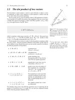
A fundamental part of many mechatronic systems is a measurement system composed of the three basic parts illustrated in Figure 1.3. The transducer is a sensing
device that converts a physical input into an output, usually a voltage. The signal
processor performs filtering, amplification, or other signal conditioning on the
transducer output. The term sensor is often used to refer to the transducer or to the
combination of transducer and signal processor. Finally, the recorder is an instrument, a computer, a hard-copy device, or simply a display that maintains the sensor
data for online monitoring or subsequent processing.
alc80237_ch01_001-010.indd 4
1/3/11 3:36 PM