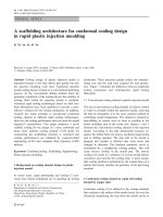
Scientific injection molding
Bạn đang xem bản rút gọn của tài liệu. Xem và tải ngay bản đầy đủ của tài liệu tại đây (78.44 MB, 141 trang )
Scientific Injection
Molding
Vishu H. Shah
Consultek Consulting Group
Part II
Hot Runner (Runnerless) Molds
In the hot runner mold, the runners are kept hot in order to keep the molten
plastic in a fluid state at all times. This is a “Runnerless” molding process and
hence the name. Hot runner molds are similar to the three plate molds, except that
the runner section of the mold is not opened during the cycle. The heated runner
plate (Manifold) is kept insulated from the rest of the relatively cooler mold.
• No runner to separate from the molded parts
• No runners to either dispose of or regrind and reprocess
• Less possibility of contamination
• Hot drops carry consistent heat at processing temperature directly into the cavity
• Balanced Melt Flow
• Lower cycle (cooling) time – cooling time not runner dependent
• No robotics (or automation) needed for runner removal
• Possibly lower injection pressure
• No sprue/runner sticking problems
• Cleaner molding environment
Hot Runner
Hot runner system in the mold is simply an
extension of the barrel
Hot Runner is not a melting device and
should not be used as such
Any time you add heat to the resin in front of the
screw you have a heated melt delivery system
Heated Sprue Bushing
Hot Runner Systems
Hot
Runner
Injection Molding Tooling
Valve Gate Shut Off System
Bushings are Opened for Injection
Injection Molding Tooling
Valve Gate Shut Off System
A Fills, Bushing A Closes
Sequential gating
Stack Molds
• Two level
• Three level
• Four level
A stack mold is a multiple two-plate mold, with molds placed one on
top of the other.
• Doubles the output from a single press
• Only 20 to 30 percent more clamping force required
• Three level and four level stack molds possible
• Additional shot capacity required
• May need more daylight
• Expensive
• High maintenance
• Technical expertise
Stack Mold
■ High Performance DVD Package Stack mold
o (2x4) Stack 7.7 second cycle w/layered cavities and air piston ejection
Innovations
®
A Company
96 cavity(4x24)
75mm Dia. Lid ; 500 Ton m/c ;
5.0s cycle; 1.5 million parts/day
o No Machine Modifications required
o Consider M/C Shutheight
o Ejector System built into mold
o Manifolds Reduce water connections
o Center Sections Supported On
Machine Tie Bars
o Significant Reduction in
production costs
o Twin VMTS Hot Runner System
■ 4 Level Stack Mold
V
M
T
S
V
M
T
S
Patented Technology
Innovations
®
A Company
Unit Dies (Master unit Die) MUD
• Description:
This mold is engineered to have a "frame", which is permanently mounted in the machine, and
an interchangeable "insert" unit, which includes the A and B plates and the ejector mechanism.
The operation of the mold is similar to an A series tool once the interchangeable insert unit is
secured in the frame.
Attributes:
Similar to an A or B series mold, plate thickness are standard. Typically used in short run (small
volume) production environments due to the ease of "mold" change.
• (+) Quick mold changes (improved production efficiencies)
• (+) Versatile
• (+) Easier maintenance (lower weight)
• (+) Easier storage (less volume)
• (+) Frequently used for short run production
• (-) Expensive (Must buy frame and inserts)
• (-) Runner typically dictates cycle time
• (-) Two plate design only
Mold Metallurgy
Molders’ Demands
• Wear resistance
• Toughness
• Compressive strength
• Hot hardness
• Corrosion resistance
• Thermal conductivity
Moldmakers’ Demands
• Hobbability
• machinability
• Polishability
• Heat-treating dimensional stability
• weldability
•Nitriding ability
Major categories of applications in molds
• Mold Cavity and Core unit components
• Mold base plates
• Special function components
(Slides, gibs, wear plates)
Material selection considerations
• Type of plastics to be molded….abrasive, corrosive etc……420 SS
• Number of parts to be molded (Alum, p-20, H-13, SS?)
• Surface finish of molded parts
• Cavity design requirements…metal to metal contacts etc.
• Method of cavity forming…Machining requirements
• Method of heat treating
Applications of Mold steels
CYCLE TIME
CYCLE TIME
CYCLE TIME
Copper Alloys
MOLDMAX
AMPCO ALLOY
Runners
The purpose of the runner system is to convey the
hot molten material from the sprue to the gate
with minimum loss in pressure.
Types of Runners
Runners control cooling time in small
parts……
Best to design runners as small as possible….
Example:if the runner diameter is increased from ¼
in. to 5/16 in.; the percentage increase in material
flow is 60 %
However, too small a runner require higher injection
pressure and may cause surface defects on parts
Runner Length
Best to design runners as short as possible to reduce heat and pressure losses
Fillet radius (min. 1/8”) a must at the intersection of secondary runner with
main runners
Diameter of the secondary runner should be smaller than primary runner
Recommended
runner sizes
Balanced runner design
Balanced runner design in a family
mold
Melt Flipper Technology
This cutaway view shows the concept
of Beaumont’s solution, the Runner
Flipper. The final product differs from
this particular design. The Flipper
reorients the temperature and shear
distribution of the melt so that when it
splits at an intersection, equal
amounts of high- and low-viscosity
material are delivered to each cavity.
These are the partially filled parts
and runner after ejection from the
mold. It’s apparent that the melt
fills the inside cavities before
filling the outside cavities.
Although the mold is four cavities,
notice that the runner system
duplicates an eight-cavity design.
Types of Gates
• Sprue Gate….used on large single cavity parts, cold slug issues
• Edge gate…Large surfaces, thin wall, keep parts attached
• Fan gate…minimize surface imperfections, reduce stress
• Sub gate…(Tunnel gate)…Automation
• Diaphragm gate…round part, avoid weld line
• Flash gate…similar to fan gate much wider, low warpage
• Ring gate…hollow tubular parts, helps with core shift
• Tab gate…stress free part and optical clarity…acrylic lens
• Sub gate into ejector pin…no gate marks