Tài liệu Text Book of Machine Design P4 ppt
Bạn đang xem bản rút gọn của tài liệu. Xem và tải ngay bản đầy đủ của tài liệu tại đây (631.53 KB, 33 trang )
Simple Stresses in Machine Parts
n
87
Simple Stresses in
Machine Parts
87
1. Introduction.
2. Load.
3. Stress.
4. Strain.
5. Tensile Stress and Strain.
6. Compressive Stress and
Strain.
7. Young's Modulus or Modulus
of Elasticity.
8. Shear Stress and Strain
9. Shear Modulus or Modulus
of Rigidity.
10. Bearing Stress.
11. Stress-Strain Diagram.
12. Working Stress.
13. Factor of Safety.
14. Selection of Factor of
Safety.
15. Stresses in Composite
Bars.
16. Stresses due to Change
in Temperature—Thermal
Stresses.
17. Linear and Lateral Strain.
18. Poisson's Ratio.
19. Volumetric Strain.
20. Bulk Modulus.
21. Relation between Bulk
Modulus and Young's
Modulus.
22. Relation between Young's
Modulus and Modulus of
Rigidity.
23. Impact Stress.
24. Resilience.
4
C
H
A
P
T
E
R
4.14.1
4.14.1
4.1
IntrIntr
IntrIntr
Intr
oductionoduction
oductionoduction
oduction
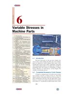
In engineering practice, the machine parts are
subjected to various forces which may be due to either one
or more of the following:
1. Energy transmitted,
2. Weight of machine,
3. Frictional resistances,
4. Inertia of reciprocating parts,
5. Change of temperature, and
6. Lack of balance of moving parts.
The different forces acting on a machine part produces
various types of stresses, which will be discussed in this
chapter.
4.24.2
4.24.2
4.2
LoadLoad
LoadLoad
Load
It is defined as any external force acting upon a
machine part. The following four types of the load are
important from the subject point of view:
CONTENTS
CONTENTS
CONTENTS
CONTENTS
88
n
A Textbook of Machine Design
1. Dead or steady load. A load is said to be a dead or steady load, when it does not change in
magnitude or direction.
2. Live or variable load. A load is said to be a live or variable load, when it changes continually.
3. Suddenly applied or shock loads. A load is said to be a suddenly applied or shock load, when
it is suddenly applied or removed.
4. Impact load. A load is said to be an impact load, when it is applied with some initial velocity.
Note: A machine part resists a dead load more easily than a live load and a live load more easily than a shock
load.
4.34.3
4.34.3
4.3
StrStr
StrStr
Str
essess
essess
ess
When some external system of forces or loads act on a body, the internal forces (equal and
opposite) are set up at various sections of the body, which resist the external forces. This internal
force per unit area at any section of the body is known as unit stress or simply a stress. It is denoted
by a Greek letter sigma (σ). Mathematically,
Stress, σ = P/A
where P = Force or load acting on a body, and
A = Cross-sectional area of the body.
In S.I. units, the stress is usually expressed in Pascal (Pa) such that 1 Pa = 1 N/m
2
. In actual
practice, we use bigger units of stress i.e. megapascal (MPa) and gigapascal (GPa), such that
1 MPa = 1 × 10
6
N/m
2
= 1 N/mm
2
and 1 GPa = 1 × 10
9
N/m
2
= 1 kN/mm
2
4.44.4
4.44.4
4.4
StrainStrain
StrainStrain
Strain
When a system of forces or loads act on a body, it undergoes some deformation. This deformation
per unit length is known as unit strain or simply a strain. It is denoted by a Greek letter epsilon (ε).
Mathematically,
Strain, ε = δl / l or δl = ε.l
where δl = Change in length of the body, and
l = Original length of the body.
4.54.5
4.54.5
4.5
TT
TT
T
ensile Strensile Str
ensile Strensile Str
ensile Str
ess and Strainess and Strain
ess and Strainess and Strain
ess and Strain
Fig. 4.1. Tensile stress and strain.
When a body is subjected to two equal and opposite axial pulls P (also called tensile load) as
shown in Fig. 4.1 (a), then the stress induced at any section of the body is known as tensile stress as
shown in Fig. 4.1 (b). A little consideration will show that due to the tensile load, there will be a
decrease in cross-sectional area and an increase in length of the body. The ratio of the increase in
length to the original length is known as tensile strain.
Simple Stresses in Machine Parts
n
89
Let P = Axial tensile force acting on the body,
A = Cross-sectional area of the body,
l = Original length, and
δl = Increase in length.
∴ Tensile stress, σ
t
= P/A
and tensile strain, ε
t
= δl / l
4.64.6
4.64.6
4.6
ComprCompr
ComprCompr
Compr
essivessiv
essivessiv
essiv
e Stre Str
e Stre Str
e Str
ess andess and
ess andess and
ess and
StrainStrain
StrainStrain
Strain
When a body is subjected to two
equal and opposite axial pushes P (also
called compressive load) as shown in
Fig. 4.2 (a), then the stress induced at any
section of the body is known as
compressive stress as shown in Fig. 4.2
(b). A little consideration will show that
due to the compressive load, there will be
an increase in cross-sectional area and a
decrease in length of the body. The ratio
of the decrease in length to the original
length is known as compressive strain.
Fig. 4.2. Compressive stress and strain.
Let P = Axial compressive force acting on the body,
A = Cross-sectional area of the body,
l = Original length, and
δl = Decrease in length.
∴ Compressive stress, σ
c
= P/A
and compressive strain, ε
c
= δ l/l
Note : In case of tension or compression, the area involved is at right angles to the external force applied.
4.74.7
4.74.7
4.7
YY
YY
Y
oung's Modulus or Modulus of Elasticityoung's Modulus or Modulus of Elasticity
oung's Modulus or Modulus of Elasticityoung's Modulus or Modulus of Elasticity
oung's Modulus or Modulus of Elasticity
Hooke's law* states that when a material is loaded within elastic limit, the stress is directly
proportional to strain, i.e.
σ∝ε or
σ
= E.
ε
∴ E =
Pl
Al
σ×
=
ε×δ
* It is named after Robert Hooke, who first established it by experiments in 1678.
Note : This picture is given as additional information and is
not a direct example of the current chapter.
Shock absorber of a motorcycle absorbs stresses.
90
n
A Textbook of Machine Design
where E is a constant of proportionality known as Young's modulus or modulus of elasticity. In S.I.
units, it is usually expressed in GPa i.e. GN/m
2
or kN/mm
2
. It may be noted that Hooke's law holds
good for tension as well as compression.
The following table shows the values of modulus of elasticity or Young's modulus (E) for the
materials commonly used in engineering practice.
TT
TT
T
aa
aa
a
ble 4.1.ble 4.1.
ble 4.1.ble 4.1.
ble 4.1.
VV
VV
V
alues of E falues of E f
alues of E falues of E f
alues of E f
or the commonly used engor the commonly used eng
or the commonly used engor the commonly used eng
or the commonly used eng
ineerineer
ineerineer
ineer
ing maing ma
ing maing ma
ing ma
terter
terter
ter
ialsials
ialsials
ials
..
..
.
Material Modulus of elasticity (E) in GPa i.e. GN/m
2
or kN/mm
2
Steel and Nickel 200 to 220
Wrought iron 190 to 200
Cast iron 100 to 160
Copper 90 to 110
Brass 80 to 90
Aluminium 60 to 80
Timber 10
Example 4.1. A coil chain of a crane required to carry a maximum load of 50 kN, is shown in
Fig. 4.3.
Fig. 4.3
Find the diameter of the link stock, if the permissible tensile stress in the link material is not to
exceed 75 MPa.
Solution. Given : P = 50 kN = 50 × 10
3
N; σ
t
= 75 MPa = 75 N/mm
2
Let d = Diameter of the link stock in mm.
∴ Area, A =
ð
4
× d
2
= 0.7854 d
2
We know that the maximum load (P),
50 × 10
3
= σ
t
. A = 75 × 0.7854 d
2
= 58.9 d
2
∴ d
2
= 50 × 10
3
/ 58.9 = 850 or d = 29.13 say 30 mm
Ans.
Example 4.2.
A cast iron link, as shown in Fig. 4.4, is required to transmit a steady tensile load
of 45 kN. Find the tensile stress induced in the link material at sections A-A and B-B.
Fig. 4.4. All dimensions in mm.
Simple Stresses in Machine Parts
n
91
Solution. Given : P = 45 kN = 45 × 10
3
N
Tensile stress induced at section A-A
We know that the cross-sectional area of link at section A-A,
A
1
= 45 × 20 = 900 mm
2
∴ Tensile stress induced at section A-A,
σ
t1
3
1
45 10
900
×
==
P
A
= 50 N/mm
2
= 50 MPa
Ans.
Tensile stress induced at section B-B
We know that the cross-sectional area of link at section B-B,
A
2
= 20 (75 – 40) = 700 mm
2
∴ Tensile stress induced at section B-B,
σ
t2
3
2
45 10
700
×
==
P
A
= 64.3 N/mm
2
= 64.3 MPa
Ans.
Example 4.3. A hydraulic press exerts a total load of 3.5 MN. This load is carried by two steel
rods, supporting the upper head of the press. If the safe stress is 85 MPa and E = 210 kN/mm
2
,
find : 1. diameter of the rods, and 2. extension in each rod in a length of 2.5 m.
Solution. Given : P = 3.5 MN = 3.5 × 10
6
N; σ
t
= 85 MPa = 85 N/mm
2
; E = 210 kN/mm
2
= 210 × 10
3
Nmm
2
; l = 2.5 m = 2.5 × 10
3
mm
1. Diameter of the rods
Let d = Diameter of the rods in mm.
∴ Area, A =
4
π
× d
2
= 0.7854 d
2
Since the load P is carried by two rods, therefore load carried by each rod,
P
1
=
6
3.5 10
22
P
×
=
= 1.75 × 10
6
N
We know that load carried by each rod (P
1
),
1.75 × 10
6
= σ
t
. A = 85 × 0.7854 d
2
= 66.76 d
2
∴ d
2
= 1.75 × 10
6
/66.76 = 26 213 or d = 162 mm
Ans.
2. Extension in each rod
Let δl = Extension in each rod.
We know that Young's modulus (E),
210 × 10
3
=
33
1
85 2.5 10 212.5 10
t
l
Pl
Al l l l
σ×
××××
== =
×δ δ δ δ
...
1
=σ
∵
t
P
A
∴ δl = 212.5 × 10
3
/(210 × 10
3
) = 1.012 mm
Ans.
Example 4.4.
A rectangular base plate is fixed at each of its four corners by a 20 mm diameter
bolt and nut as shown in Fig. 4.5. The plate rests on washers of 22 mm internal diameter and
50 mm external diameter. Copper washers which are placed between the nut and the plate are of
22 mm internal diameter and 44 mm external diameter.
92
n
A Textbook of Machine Design
If the base plate carries a load of 120 kN (including
self-weight, which is equally distributed on the four corners),
calculate the stress on the lower washers before the nuts are
tightened.
What could be the stress in the upper and lower washers,
when the nuts are tightened so as to produce a tension of
5 kN on each bolt?
Solution. Given : d = 20 mm ; d
1
= 22 mm ; d
2
= 50
mm ; d
3
= 22 mm ; d
4
= 44 mm ; P
1
= 120 kN ; P
2
= 5 kN
Stress on the lower washers before the nuts are
tightened
We know that area of lower washers,
A
1
=
22 2 2
21
( ) ( ) (50) (22)
44
dd
ππ
−= −
= 1583 mm
2
and area of upper washers,
A
2
=
22 22
43
( ) ( ) (44) (22)
44
dd
ππ
−= −
= 1140 mm
2
Since the load of 120 kN on the four washers is equally distributed, therefore load on each
lower washer before the nuts are tightened,
P
1
=
120
4
= 30 kN = 30 000 N
We know that stress on the lower washers before the nuts are tightened,
σ
c1
=
1
1
30 000
1583
=
P
A
= 18.95 N/mm
2
= 18.95 MPa
Ans.
Stress on the upper washers when the nuts are tightened
Tension on each bolt when the nut is tightened,
P
2
= 5 kN = 5000 N
∴ Stress on the upper washers when the nut is tightened,
σ
c2
=
2
2
5000
1140
=
P
A
= 4.38 N/mm
2
= 4.38 MPa
Ans.
Stress on the lower washers when the nuts are tightened
We know that the stress on the lower washers when the nuts are tightened,
σ
c3
=
12
1
30 000 5000
1583
++
=
PP
A
= 22.11 N/mm
2
= 22.11 MPa
Ans.
Example 4.5.
The piston rod of a steam engine is 50 mm in diameter and 600 mm long. The
diameter of the piston is 400 mm and the maximum steam pressure is 0.9 N/mm
2
. Find the compres-
sion of the piston rod if the Young's modulus for the material of the piston rod is 210 kN/mm
2
.
Solution. Given : d = 50 mm ; l = 600 mm ; D = 400 mm ; p = 0.9 N/mm
2
; E = 210 kN/mm
2
= 210 × 10
3
N/mm
2
Let δl = Compression of the piston rod.
We know that cross-sectional area of piston,
=
4
π
× D
2
=
4
π
(400)
2
= 125 680 mm
2
∴ Maximum load acting on the piston due to steam,
P = Cross-sectional area of piston × Steam pressure
= 125 680 × 0.9 = 113 110 N
Fig. 4.5
Simple Stresses in Machine Parts
n
93
We also know that cross-sectional area of piston rod,
A =
4
π
× d
2
=
4
π
(50)
2
= 1964 mm
2
and Young's modulus (E),
210 × 10
3
=
×
×δ
Pl
Al
113 110 600 34 555
1964
×
==
×δ δ
ll
∴δl = 34 555 / (210 × 10
3
)
= 0.165 mm
Ans.
4.84.8
4.84.8
4.8
Shear StrShear Str
Shear StrShear Str
Shear Str
ess and Strainess and Strain
ess and Strainess and Strain
ess and Strain
When a body is subjected to two equal and opposite
forces acting tangentially across the resisting section, as a
result of which the body tends to shear off the section, then the stress induced is called shear stress.
Fig. 4.6. Single shearing of a riveted joint.
The corresponding strain is known as shear strain and it is measured by the angular deformation
accompanying the shear stress. The shear stress and shear strain are denoted by the Greek letters tau
(τ) and phi (φ) respectively. Mathematically,
Shear stress, τ =
Tangential force
Resisting area
Consider a body consisting of two plates connected by a rivet as shown in Fig. 4.6 (a). In this
case, the tangential force P tends to shear off the rivet at one cross-section as shown in Fig. 4.6 (b). It
may be noted that when the tangential force is resisted by one cross-section of the rivet (or when
shearing takes place at one cross-section of the rivet), then the rivets are said to be in single shear. In
such a case, the area resisting the shear off the rivet,
A =
2
4
π
×
d
and shear stress on the rivet cross-section,
τ =
2
2
4
4
==
π
π
×
PP P
A
d
d
Now let us consider two plates connected by the two cover plates as shown in Fig. 4.7 (a). In
this case, the tangential force P tends to shear off the rivet at two cross-sections as shown in Fig. 4.7
(b). It may be noted that when the tangential force is resisted by two cross-sections of the rivet (or
This picture shows a jet engine being
tested for bearing high stresses.
94
n
A Textbook of Machine Design
when the shearing takes place at two cross-sections of the rivet), then the rivets are said to be in
double shear. In such a case, the area resisting the shear off the rivet,
A =
2
2
4
d
π
××
... (For double shear)
and shear stress on the rivet cross-section,
τ=
2
2
2
2
4
PP P
A
d
d
==
π
π
××
Fig. 4.7. Double shearing of a riveted joint.
Notes : 1. All lap joints and single cover butt joints are in single shear, while the butt joints with double cover
plates are in double shear.
2. In case of shear, the area involved is parallel to the external force applied.
3. When the holes are to be punched or drilled in the metal plates, then the tools used to perform the
operations must overcome the ultimate shearing resistance of the material to be cut. If a hole of diameter ‘d’ is
to be punched in a metal plate of thickness ‘t’, then the area to be sheared,
A = π d × t
and the maximum shear resistance of the tool or the force required to punch a hole,
P = A × τ
u
= π d × t × τ
u
where τ
u
= Ultimate shear strength of the material of the plate.
4.94.9
4.94.9
4.9
Shear Modulus or Modulus of RigidityShear Modulus or Modulus of Rigidity
Shear Modulus or Modulus of RigidityShear Modulus or Modulus of Rigidity
Shear Modulus or Modulus of Rigidity
It has been found experimentally that within the elastic limit, the shear stress is directly
proportional to shear strain. Mathematically
τ∝ φ or τ = C . φ or τ / φ = C
where τ = Shear stress,
φ = Shear strain, and
C = Constant of proportionality, known as shear modulus or modulus
of rigidity. It is also denoted by N or G.
The following table shows the values of modulus of rigidity (C) for the materials in every day
use:
TT
TT
T
aa
aa
a
ble 4.2.ble 4.2.
ble 4.2.ble 4.2.
ble 4.2.
VV
VV
V
alues of alues of
alues of alues of
alues of
CC
CC
C
f f
f f
f
or the commonly used maor the commonly used ma
or the commonly used maor the commonly used ma
or the commonly used ma
terter
terter
ter
ialsials
ialsials
ials
..
..
.
Material Modulus of rigidity (C) in GPa i.e. GN/m
2
or kN/mm
2
Steel 80 to 100
Wrought iron 80 to 90
Cast iron 40 to 50
Copper 30 to 50
Brass 30 to 50
Timber 10
Simple Stresses in Machine Parts
n
95
Example 4.6. Calculate the force required to punch a circular blank of 60 mm diameter in a
plate of 5 mm thick. The ultimate shear stress of the plate is 350 N/mm
2
.
Solution. Given: d = 60 mm ; t = 5 mm ;
τ
u
= 350 N/mm
2
We know that area under shear,
A = π d ×
τ
= π × 60 × 5 = 942.6 mm
2
and force required to punch a hole,
P = A ×
τ
u
= 942.6 × 350 = 329 910 N = 329.91 kN
Ans.
Example 4.7. A pull of 80 kN is transmitted from a bar X to the bar Y through a pin as shown
in Fig. 4.8.
If the maximum permissible tensile stress in the bars is 100 N/mm
2
and the permissible shear
stress in the pin is 80 N/mm
2
, find the diameter of bars and of the pin.
Fig. 4.8
Solution. Given : P = 80 kN = 80 × 10
3
N;
σ
t
= 100 N/mm
2
; τ = 80 N/mm
2
Diameter of the bars
Let D
b
= Diameter of the bars in mm.
∴ Area, A
b
=
4
π
(D
b
)
2
= 0.7854 (D
b
)
2
We know that permissible tensile stress in the bar
(σ
t
),
3
22
80 10 101 846
100
0.7854 ( ) ( )
×
== =
b
bb
P
A
DD
∴ (D
b
)
2
= 101 846 / 100 = 1018.46
or D
b
= 32 mm
Ans.
Diameter of the pin
Let D
p
= Diameter of the pin in mm.
Since the tensile load P tends to shear off the pin at two sections i.e. at AB and CD, therefore the
pin is in double shear.
∴ Resisting area,
A
p
= 2 ×
4
π
(D
p
)
2
= 1.571 (D
p
)
2
We know that permissible shear stress in the pin (τ),
33
22
80 10 50.9 10
80
1.571 ( ) ( )
××
== =
p
pp
P
A
DD
∴ (D
p
)
2
= 50.9 × 10
3
/80 = 636.5 or D
p
= 25.2 mm
Ans.
High force injection moulding machine.
Note : This picture is given as additional information
and is not a direct example of the current chapter.
96
n
A Textbook of Machine Design
4.104.10
4.104.10
4.10
Bear Bear
Bear Bear
Bear
ing String Str
ing String Str
ing Str
essess
essess
ess
A localised compressive stress at the surface of contact between two members of a machine
part, that are relatively at rest is known as bearing stress or crushing stress. The bearing stress is
taken into account in the design of riveted joints, cotter joints, knuckle joints, etc. Let us consider a
riveted joint subjected to a load P as shown in Fig. 4.9. In such a case, the bearing stress or crushing
stress (stress at the surface of contact between the rivet and a plate),
σ
b
(or σ
c
)=
..
P
dtn
where d = Diameter of the rivet,
t = Thickness of the plate,
d.t = Projected area of the rivet, and
n = Number of rivets per pitch length in bearing or crushing.
Fig. 4.9. Bearing stress in a riveted joint. Fig. 4.10. Bearing pressure in a journal
supported in a bearing.
It may be noted that the local compression which exists at the surface of contact between two
members of a machine part that are in relative motion, is called bearing pressure (not the bearing
stress). This term is commonly used in the design of a journal supported in a bearing, pins for levers,
crank pins, clutch lining, etc. Let us consider a journal rotating in a fixed bearing as shown in Fig.
4.10 (a). The journal exerts a bearing pressure on the curved surfaces of the brasses immediately
below it. The distribution of this bearing pressure will not be uniform, but it will be in accordance
with the shape of the surfaces in contact and deformation characteristics of the two materials. The
distribution of bearing pressure will be similar to that as shown in Fig. 4.10 (b). Since the actual
bearing pressure is difficult to determine, therefore the average bearing pressure is usually calculated
by dividing the load to the projected area of the curved surfaces in contact. Thus, the average bearing
pressure for a journal supported in a bearing is given by
p
b
=
.
P
ld
where p
b
= Average bearing pressure,
P = Radial load on the journal,
l = Length of the journal in contact, and
d = Diameter of the journal.
Simple Stresses in Machine Parts
n
97
Example 4.8. Two plates 16 mm thick are
joined by a double riveted lap joint as shown in
Fig. 4.11. The rivets are 25 mm in diameter.
Find the crushing stress induced between
the plates and the rivet, if the maximum tensile
load on the joint is 48 kN.
Solution. Given : t = 16 mm ; d = 25 mm ;
P = 48 kN = 48 × 10
3
N
Since the joint is double riveted, therefore, strength of two rivets in bearing (or crushing) is
taken. We know that crushing stress induced between the plates and the rivets,
σ
c
=
3
48 10
. . 25 16 2
P
dtn
×
=
××
= 60 N/mm
2
Ans.
Example 4.9. A journal 25 mm in diameter supported in sliding bearings has a maximum end
reaction of 2500 N. Assuming an allowable bearing pressure of 5 N/mm
2
, find the length of the
sliding bearing.
Solution. Given : d = 25 mm ; P = 2500 N ; p
b
= 5 N/mm
2
Let l = Length of the sliding bearing in mm.
We know that the projected area of the bearing,
A = l × d = l × 25 = 25 l mm
2
∴ Bearing pressure ( p
b
),
5=
2500 100 100
or
25 5
== =
P
l
All
= 20 mm
Ans.
4.114.11
4.114.11
4.11
StrStr
StrStr
Str
ess-strain Diagramess-strain Diagram
ess-strain Diagramess-strain Diagram
ess-strain Diagram
In designing various parts of a machine, it is
necessary to know how the material will function
in service. For this, certain characteristics or
properties of the material should be known. The
mechanical properties mostly used in mechanical
engineering practice are commonly determined
from a standard tensile test. This test consists of
gradually loading a standard specimen of a material
and noting the corresponding values of load and
elongation until the specimen fractures. The load
is applied and measured by a testing machine. The
stress is determined by dividing the load values by
the original cross-sectional area of the specimen.
The elongation is measured by determining the
amounts that two reference points on the specimen
are moved apart by the action of the machine. The
original distance between the two reference points
is known as gauge length. The strain is determined
by dividing the elongation values by the gauge
length.
The values of the stress and corresponding
strain are used to draw the stress-strain diagram of the material tested. A stress-strain diagram for a
mild steel under tensile test is shown in Fig. 4.12 (a). The various properties of the material are
discussed below :
Fig. 4.11
In addition to bearing the stresses, some
machine parts are made of stainless steel to
make them corrosion resistant.
Note : This picture is given as additional information
and is not a direct example of the current chapter.
98
n
A Textbook of Machine Design
1. Proportional limit. We see from the diagram
that from point O to A is a straight line, which represents
that the stress is proportional to strain. Beyond point A,
the curve slightly deviates from the straight line. It is
thus obvious, that Hooke's law holds good up to point A
and it is known as proportional limit. It is defined as
that stress at which the stress-strain curve begins to de-
viate from the straight line.
2. Elastic limit. It may be noted that even if the
load is increased beyond point A upto the point B, the
material will regain its shape and size when the load is
removed. This means that the material has elastic
properties up to the point B. This point is known as elastic
limit. It is defined as the stress developed in the material
without any permanent set.
Note: Since the above two limits are very close to each other,
therefore, for all practical purposes these are taken to be equal.
3. Yield point. If the material is stressed beyond
point B, the plastic stage will reach i.e. on the removal
of the load, the material will not be able to recover its
original size and shape. A little consideration will show
that beyond point B, the strain increases at a faster rate with any increase in the stress until the point
C is reached. At this point, the material yields before the load and there is an appreciable strain
without any increase in stress. In case of mild steel, it will be seen that a small load drops to D,
immediately after yielding commences. Hence there are two yield points C and D. The points C and
D are called the upper and lower yield points respectively. The stress corresponding to yield point is
known as yield point stress.
4. Ultimate stress. At D, the specimen regains some strength and higher values of stresses are
required for higher strains, than those between A and D. The stress (or load) goes on increasing till the
A crane used on a ship.
Note : This picture is given as additional information and is not a direct example of the current chapter.
Fig. 4.12. Stress-strain diagram
for a mild steel.
Simple Stresses in Machine Parts
n
99
point E is reached. The gradual increase in the strain (or length) of the specimen is followed with the
uniform reduction of its cross-sectional area. The work done, during stretching the specimen, is
transformed largely into heat and the
specimen becomes hot. At E, the
stress, which attains its maximum
value is known as ultimate stress. It
is defined as the largest stress
obtained by dividing the largest value
of the load reached in a test to the
original cross-sectional area of the
test piece.
5. Breaking stress. After the
specimen has reached the ultimate
stress, a neck is formed, which
decreases the cross-sectional area of
the specimen, as shown in Fig. 4.12
(b). A little consideration will show
that the stress (or load) necessary to
break away the specimen, is less than
the maximum stress. The stress is, therefore, reduced until the specimen breaks away at point F. The
stress corresponding to point F is known as breaking stress.
Note : The breaking stress (i.e. stress at F which is less than at E) appears to be somewhat misleading. As the
formation of a neck takes place at E which reduces the cross-sectional area, it causes the specimen suddenly
to fail at F. If for each value of the strain between E and F, the tensile load is divided by the reduced cross-
sectional area at the narrowest part of the neck, then the true stress-strain curve will follow the dotted line EG.
However, it is an established practice, to calculate strains on the basis of original cross-sectional area of the
specimen.
6. Percentage reduction in area. It is the difference between the original cross-sectional area
and cross-sectional area at the neck (i.e. where the fracture takes place). This difference is expressed
as percentage of the original cross-sectional area.
Let A = Original cross-sectional area, and
a = Cross-sectional area at the neck.
Then reduction in area = A – a
and percentage reduction in area =
100
Aa
A
−
×
7. Percentage elongation. It is the percentage increase in the standard gauge length (i.e. original
length) obtained by measuring the fractured specimen after bringing the broken parts together.
Let l = Gauge length or original length, and
L = Length of specimen after fracture or final length.
∴ Elongation = L – l
and percentage elongation =
100
Ll
l
−
×
Note : The percentage elongation gives a measure of ductility of the metal under test. The amount of local
extensions depends upon the material and also on the transverse dimensions of the test piece. Since the specimens
are to be made from bars, strips, sheets, wires, forgings, castings, etc., therefore it is not possible to make all
specimens of one standard size. Since the dimensions of the specimen influence the result, therefore some
standard means of comparison of results are necessary.
A recovery truck with crane.
Note : This picture is given as additional information and is not a
direct example of the current chapter.