TIMER RELAY RE17LMBM SCHNEIDER
Bạn đang xem bản rút gọn của tài liệu. Xem và tải ngay bản đầy đủ của tài liệu tại đây (113.64 KB, 9 trang )
Product data sheet
Characteristics
RE17LMBM
time delay relay 10 functions - 1 s..100 h 24..240 V - solid state output
Range of product
Zelio Time
Product or component
type
Modular timing relay
Discrete output type
Solid state
Width
17.5 mm
Component name
RE17L
Time delay type
A
Ac
At
B
Bw
C
D
Di
H
Ht
Time delay range
0.1...1 s
1...10 h
1...10 min
1...10 s
10...100 h
6...60 min
6...60 s
Nominal output current
0.7 A
The information provided in this documentation contains general descriptions and/or technical characteristics of the performance of the products contained herein.
This documentation is not intended as a substitute for and is not to be used for determining suitability or reliability of these products for specific user applications.
It is the duty of any such user or integrator to perform the appropriate and complete risk analysis, evaluation and testing of the products with respect to the relevant specific application or use thereof.
Neither Schneider Electric Industries SAS nor any of its affiliates or subsidiaries shall be responsible or liable for misuse of the information contained herein.
Main
Complementary
Control type
Selector switch on front panel
[Us] rated supply voltage
24...240 V AC at 50/60 Hz
Voltage range
0.85...1.1 Us
Supply frequency
50...60 Hz (+/- 5 %)
Release of input voltage
8V
Control signal pulse width
0.05 s typical
Insulation resistance
100 MOhm at 500 V DC conforming to IEC 60664-1
[Uimp] rated impulse withstand voltage
5 kV (1.2/50 µs)
Power on delay
< 100 ms
Connections - terminals
Screw terminals, clamping capacity: 2 x 0.2...2 x 1.5 mm² AWG 24...AWG 16
(flexible) with cable end
Screw terminals, clamping capacity: 1 x 0.2...1 x 2.5 mm² AWG 24...AWG 14
(flexible) with cable end
Screw terminals, clamping capacity: 2 x 0.5...2 x 2.5 mm² AWG 20...AWG 14
(solid) without cable end
Screw terminals, clamping capacity: 1 x 0.5...1 x 3.3 mm² AWG 20...AWG 12
(solid) without cable end
Tightening torque
0.6...1 N.m conforming to IEC 60947-1
Dielectric strength
2.5 kV 1 mA/1 minute 50 Hz conforming to IEC 61812-1
Housing material
Self-extinguishing
Repeat accuracy
+/- 0.5 % conforming to IEC 61812-1
Temperature drift
+/- 0.05 %/°C
Voltage drift
+/- 0.2 %/V
Setting accuracy of time delay
+/- 10 % of full scale at 25 °C conforming to IEC 61812-1
Reset time
350 ms on de-energisation typical
On-load factor
100 %
Sep 9, 2015
1
Power consumption in VA
<= 3 VA at 240 V AC
Power consumption in W
<= 1.5 W at 240 V DC
Breaking capacity
0.7 A AC/DC at 20 °C
0.5 A AC/DC conforming to UL
Operating frequency
10 Hz
Maximum output current
20 A <= 10 ms
Minimum switching current
10 mA
Leakage current
< 5 mA
Maximum switching voltage
250 V AC
Voltage drop
8 V 2-wire
4 V 3-wire
Electrical durability
100000000 cycles
Marking
CE
Creepage distance
4 kV/3 conforming to IEC 60664-1
Mounting position
Any position in relation to normal vertical mounting plane
Mounting support
35 mm DIN rail conforming to EN/IEC 60715
Product weight
0.068 kg
Environment
Immunity to microbreaks
<= 20 ms
Derating factor
5 mA/°C
Standards
2004/108/EC
EN 61000-6-1
EN 61000-6-2
EN 61000-6-3
EN 61000-6-4
IEC 61812-1
2006/95/EC
Product certifications
CSA
CULus
GL
Ambient air temperature for storage
-30...60 °C
Ambient air temperature for operation
-20...60 °C
IP degree of protection
IP50 (front panel) conforming to IEC 60529
IP40 (housing) conforming to IEC 60529
IP20 (terminal block) conforming to IEC 60529
Vibration resistance
20 m/s² (f = 10...150 Hz) conforming to IEC 60068-2-6
Shock resistance
15 gn (duration = 11 ms) conforming to IEC 60068-2-27
Relative humidity
93 % without condensation conforming to IEC 60068-2-30
Electromagnetic compatibility
Conducted and radiated emissions conforming to EN 55022 class B
Voltage dips and interruptions immunity test, 25/30 cycles at 70 % conforming to
IEC 61000-4-11
Voltage dips and interruptions immunity test, 1 cycle at 0 % conforming to IEC
61000-4-11
Conducted RF disturbances, 0.15...80 MHz at 10 V conforming to IEC 61000-4-6
level 3
1.2/50 µs shock waves immunity test, common mode at 2 kV conforming to IEC
61000-4-5 level 3
1.2/50 µs shock waves immunity test, differential mode at 1 kV conforming to IEC
61000-4-5 level 3
Electrical fast transient/burst immunity test, direct at 2 kV conforming to IEC
61000-4-4 level 3
Electrical fast transient/burst immunity test, capacitive connecting clip at 1 kV
conforming to IEC 61000-4-4 level 3
Susceptibility to electromagnetic fields, 80 MHz to 1 GHz at 10 V/m conforming to
IEC 61000-4-3 level 3
Electrostatic discharge immunity test, in air at 8 kV conforming to IEC 61000-4-2
level 3
Electrostatic discharge immunity test, in contact at 6 kV conforming to IEC
61000-4-2 level 3
2
Offer Sustainability
Sustainable offer status
RoHS (date code: YYWW)
Green Premium product
Compliant - since 1243 -
Schneider Electric declaration of conformity
REACh
Reference not containing SVHC above the threshold
Product environmental profile
Available
Product end of life instructions
Available
3
Product data sheet
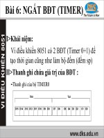
Dimensions Drawings
Width 17.5 mm
4
RE17LMBM
Product data sheet
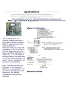
Connections and Schema
RE17LMBM
Internal Wiring Diagram
Wiring Diagram
(1) Contact Y1:
● Control for functions B, C, Ac, Bw.
● Partial stop for functions At, Ht.
● Function D if Di selected.
● Not used for functions A and H.
5
Product data sheet
Technical Description
RE17LMBM
Function A : Power on Delay Relay
Description
The timing period T begins on energisation. After timing, the output(s) R close(s). The second output can be either timed or instantaneous.
Function: 1 Output
Function: 2 Outputs
2 timed outputs (R1/R2) or 1 timed output (R1) and 1 instantaneous output (R2 inst.)
Function Ac : On- and Off-Delay Relay with Control Signal
Description
After power-up, closing of the control contact C causes the timing period T to start (timing can be interrupted by operating the Gate control
contact G). At the end of this timing period, the relay closes.
When control contact C re-opens, the timing T starts.
At the end of this timing period T, the output reverts to its initial position (timing can be interrupted by operating the Gate control contact G).
The second output can be either timed or instantaneous.
Function: 1 Output
Function: 2 Outputs
2 timed outputs (R1/R2) or 1 timed output (R1) and 1 instantaneous output (R2 inst.)
Function At : Power on Delay Relay (Summation) with Control Signal
Description
After power-up, the first opening of control contact C starts the timing. Timing can be interrupted each time control contact closes. When the
cumulative total of time periods elapsed reaches the pre-set value T, the output relay closes.
6
Function: 1 Output
T = t1 + t2 +...
Function B : Interval Relay with Control Signal
Description
After power-up, pulsing or maintaining control contact C starts the timing T. The output R closes for the duration of the timing period T then
reverts to its initial state.
Function: 1 Output
Function Bw : Double Interval Relay with Control Signal
Description
On closing and opening of control contact C, the output R closes for the duration of the timing period T.
Function: 1 Output
Function C : Off-Delay Relay with Control Signal
Description
After power-up and closing of the control contact C, the output R closes. When control contact C re-opens, timing T starts. At the end of the
timing period, the output(s) R revert(s) to its/their initial state. The second output can be either timed or instantaneous.
Function: 1 Output
Function: 2 Outputs
2 timed outputs (R1/R2) or 1 timed output (R1) and 1 instantaneous output (R2 inst.)
Function D : Symmetrical Flasher Relay (Starting Pulse Off)
Description
Repetitive cycle with two timing periods T of equal duration, with output(s) R changing state at the end of each timing period T.
The second output can be either timed or instantaneous.
7
Function: 1 Output
Function: 2 Outputs
2 timed outputs (R1/R2) or 1 timed output (R1) and 1 instantaneous output (R2 inst.)
Function Di : Symmetrical Flasher Relay (Starting Pulse On)
Description
Repetitive cycle with two timing periods T of equal duration, with output(s) R changing state at the end of each timing period T.
The second output can be either timed or instantaneous.
Function: 1 Output
Function: 2 Outputs
2 timed outputs (R1/R2) or 1 timed output (R1) and 1 instantaneous output (R2 inst.)
Function H : Interval Relay
Description
On energisation of the relay, timing period T starts and the output(s) R close(s). At the end of the timing period T, the output(s) R revert(s) to
its/their initial state. The second output can be either timed or instantaneous.
Function: 1 Output
Function: 2 Outputs
2 timed outputs (R1/R2) or 1 timed output (R1) and 1 instantaneous output (R2 inst.)
Function Ht : Interval Relay (Summation) with Control Signal
Description
On energisation, the output R closes for the duration of a timing period T then reverts to its initial state.
Pulsing or maintaining control contact C will again close the output R.
Timing T is only active when control contact C is released and so the output R will not revert to its initial state until after a time t1 + t2 +...
8
The relay memorises the total, cumulative opening time of control contact C and, once the set time T is reached, the output R reverts to its
initial state.
Function: 1 Output
T = t1 + t2 +...
Legend
Relay de-energised
Relay energised
Output open
Output closed
C Control contact
G Gate
R Relay or solid state output
R1/ 2 timed outputs
R2
R2 The second output is instantaneous if the right position is selected
inst.
T Timing period
Ta Adjustable On-delay
Tr Adjustable Off-delay
U Supply
9