steam flow meter EH prowirl 73
Bạn đang xem bản rút gọn của tài liệu. Xem và tải ngay bản đầy đủ của tài liệu tại đây (2.27 MB, 146 trang )
BA094D/06/en/12.03
50106435
Valid as of software version:
V 1.00.00 (amplifier)
PROline Prowirl 73
Vortex Flow Measuring System
4...20 mA HART
Operating Instructions
Brief operating instructions
PROline Prowirl 73
Brief operating instructions
These brief operating instructions explain how to commission your measuring device
quickly and easily:
Safety instructions
Page 7
▼
Installation
Page 11
▼
Wiring
Page 21
▼
Display and operating elements
Page 29
▼
Commissioning with “QUICK SETUP”
Page 43
You can commission your measuring device quickly and easily using the special
“Quick Setup” menu. It allows you to configure important basic functions via the
local display, for example display language, measured variables, engineering
units, signal type etc.
▼
Customer-specific configuration/
Description of device functions
Page 79 ff.
Complex measurement tasks require the configuration of additional functions
which you can individually select, set and adapt to your process conditions
using the function matrix. The function matrix of the measuring device and all the
functions are described in detail in the “Description of device functions” section.
2
Endress+Hauser
PROline Prowirl 73
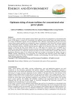
QUICK SETUP for quick commissioning
QUICK SETUP for quick commissioning
-
Esc
E
+
++
Quick Setup
E+
E
Quick Setup
Inbetriebnahme
Language
Select Fluid
Saturated
Steam
Gas
volume
Liquid
volume
Water
User defined
liquid
Unit
mass flow
Unit
volume flow
Unit
volume flow
Unit
volume flow
Temperature
value
Reference
temperature
Operating
pressure
Unit
Corr. vol. flow
Unit
Corr. vol. flow
Unit
totalizer 1
Unit
totalizer 1+2
Unit
totalizer 1+2
Unit
totalizer 1
Unit
density
Operating
pressure
Unit
mass flow
Unit
totalizer 1
Unit
volume flow
Unit
heat flow
Unit
heat flow
Density
value
Unit
Corr. vol. flow
Unit
totalizer 1
Unit
volume flow
Unit
totalizer 1
Unit
totalizer 2
Unit
totalizer 2
Expansion
coefficient
Unit
totalizer 1
Unit
heat flow
Unit
totalizer 2
Unit
totalizer 2
Unit
mass flow
Unit
volume flow
Unit
totalizer 2
Unit
totalizer 1
Unit
totalizer 2
Compressed
air
Superheated
Steam
Real gas
Natural gas
NX-19
Unit
volume flow
Unit
totalizer 2
Frequency
output
Selection output type
Selection
frequency
Seletion
pulse
Selection
status
Assign
current
Assign
frequency
Assign
pulse
Assign
status
Current
range
End value
frequency
Pulse
value
Switch on
point
Value
4 mA
Value
f low
Pulse
width
Switch off
point
Value
20 mA
Value
f high
Output
signal
Time
constant
Time
constant
Output
signal
Failsafe
mode
Failsafe
mode
Time
constant
Current
output
Quit
Failsafe
mode
Yes
Configurate another output ?
No
Yes
Automatic configuration of display ?
No
Automatic parameterization
of the display
Only by selection:
Real gas,
Natural gas NX-19
YES (recommended)
Call up the group FLOW COMPUTER ?
No
The group FLOW
COMPUTER is called up
F06-73xxxxxx-19-xx-xx-en-000
Endress+Hauser
3
QUICK SETUP for quick commissioning
!
PROline Prowirl 73
Note!
The QUICK SETUP COMMISSIONING function is described on Page 87.
X
• The display returns to the QUICK SETUP COMMISSIONING cell if you press the
during interrogation.
ESC key combination
• ➀ If the fluid selected is changed, the following parameters are reset to their factory
settings:
In group
Parameter
Sytem units
→ all parameters
Display
→ 100% Value Line 1, 100% Value Line 2
Current output
→ all parameters
Frequency output
→ all parameters
Process parameter
→ all parameters
System parameter
→ all parameters
• ➁ Only the output (current output or frequency output) not yet configured in the
current Quick Setup is offered for selection after the first cycle.
• ➂ The “YES” option appears as long as a free output is still available. “NO” is the only
option displayed when no further outputs are available.
• ➃ When “YES” is selected, the volume flow is assigned to line 1 of the local display
and the temperature to line 2.
• ➄ The SELECT FLUID function is called up. Confirm the fluid selected in this function
and configure all the subsequent functions of the FLOW COMPUTER group.
Configuration is complete if group selection is displayed. You can get back to the
Home position by means of the ESC key combination ( ).
X
• Totalizer assignment depends on the fluid selected:
4
Selected fluid:
Totalizer 1 assignment:
Totalizer 2 assignment:
Saturated steam
→ Mass flow
→ Heat flow
Superheated steam
→ Mass flow
→ Heat flow
Water
→ Volume flow
→ Heat flow
Customer-spec. liquid
→ Mass flow
→ Volume flow
Compressed air
→ Corrected volume flow
→ Volume flow
Natural Gas NX-19
→ Corrected volume flow
→ Volume flow
Gas volume
→ Volume flow
→ Volume flow
Liquid volume
→ Volume flow
→ Volume flow
Endress+Hauser
PROline Prowirl 73
Contents
Contents
1
Safety instructions . . . . . . . . . . . . . . . . . 7
5
Operation . . . . . . . . . . . . . . . . . . . . . . . . . 29
1. 1
1. 2
1. 3
1. 4
1. 5
Designated use . . . . . . . . . . . . . . . . . . . . . . . .
Installation, commissioning and operation . . .
Operational safety . . . . . . . . . . . . . . . . . . . . . .
Return . . . . . . . . . . . . . . . . . . . . . . . . . . . . . . .
Notes on safety conventions and icons . . . . . .
5. 1
5. 2
2
Identification . . . . . . . . . . . . . . . . . . . . . . 9
2. 1
2. 2
2. 3
Device designation . . . . . . . . . . . . . . . . . . . . . 9
2.1.1
Nameplate of the transmitter . . . . . . . 9
2.1.2
Nameplate of the sensor,
remote version . . . . . . . . . . . . . . . . . 10
CE mark, declaration of conformity . . . . . . . . 10
Registered trademarks . . . . . . . . . . . . . . . . . 10
Display and operating elements . . . . . . . . . . . 29
The function matrix: layout and use . . . . . . . . 30
5.2.1
General notes . . . . . . . . . . . . . . . . . . 31
5.2.2
Enabling the programming mode . . . 31
5.2.3
Disabling the programming mode . . 31
Error message display . . . . . . . . . . . . . . . . . . 32
Communication (HART) . . . . . . . . . . . . . . . . . 33
5.4.1
Operating options . . . . . . . . . . . . . . . 33
5.4.2
Device variables and process
variables . . . . . . . . . . . . . . . . . . . . . . 34
5.4.3
Universal / common practice
HART commands . . . . . . . . . . . . . . . 35
5.4.4
Device status / error messages . . . . 39
5.4.5
Switching HART write protection
on/off . . . . . . . . . . . . . . . . . . . . . . . . . 41
3
Installation . . . . . . . . . . . . . . . . . . . . . . . . 11
3. 1
3. 4
Incoming acceptance, transport, storage . . . 11
3.1.1
Incoming acceptance . . . . . . . . . . . 11
3.1.2
Transport . . . . . . . . . . . . . . . . . . . . . 11
3.1.3
Storage . . . . . . . . . . . . . . . . . . . . . . . 11
Installation conditions . . . . . . . . . . . . . . . . . . 12
3.2.1
Dimensions . . . . . . . . . . . . . . . . . . . 12
3.2.2
Installation location . . . . . . . . . . . . . 12
3.2.3
Orientation . . . . . . . . . . . . . . . . . . . . .13
3.2.4
Heat insulation . . . . . . . . . . . . . . . . . .14
3.2.5
Inlet and outlet run . . . . . . . . . . . . . . .15
3.2.6
Vibrations . . . . . . . . . . . . . . . . . . . . . 16
3.2.7
Limiting flow . . . . . . . . . . . . . . . . . . . 16
Installation instructions . . . . . . . . . . . . . . . . . 17
3.3.1
Mounting the sensor . . . . . . . . . . . . 17
3.3.2
Rotating the transmitter housing . . . 18
3.3.3
Mounting the transmitter (remote
version) . . . . . . . . . . . . . . . . . . . . . . .19
3.3.4
Rotating the local display . . . . . . . . . .20
Post-installation check . . . . . . . . . . . . . . . . . . 20
4
Wiring . . . . . . . . . . . . . . . . . . . . . . . . . . . . . 21
4. 1
Connecting the remote version . . . . . . . . . . . 21
4.1.1
Connecting the sensor . . . . . . . . . . . 21
4.1.2
Cable specifications . . . . . . . . . . . . .22
Connecting the measuring unit . . . . . . . . . . . 22
4.2.1
Connecting the transmitter . . . . . . . . 22
4.2.2
Terminal assignment . . . . . . . . . . . . 25
4.2.3
HART connection . . . . . . . . . . . . . . . .26
Degree of protection . . . . . . . . . . . . . . . . . . . 27
Post-connection check . . . . . . . . . . . . . . . . . 27
3. 2
3. 3
4. 2
4. 3
4. 4
Endress+Hauser
7
7
7
8
8
5. 3
5. 4
6
Commissioning . . . . . . . . . . . . . . . . . . . 43
6. 1
6. 2
Function check . . . . . . . . . . . . . . . . . . . . . . . .
Commissioning . . . . . . . . . . . . . . . . . . . . . . . .
6.2.1
Switching on the measuring device .
6.2.2
“Commissioning” Quick Setup . . . . .
7
Maintenance . . . . . . . . . . . . . . . . . . . . . . 46
8
Accessories . . . . . . . . . . . . . . . . . . . . . . . 47
9
Trouble-shooting . . . . . . . . . . . . . . . . . 49
9. 1
9. 2
9.3
9. 4
9. 5
9. 6
9. 7
Trouble-shooting instructions . . . . . . . . . . . . . 49
System error messages . . . . . . . . . . . . . . . . . 50
Process error messages . . . . . . . . . . . . . . . . . 54
Process errors without messages . . . . . . . . . . 55
Response of outputs to errors . . . . . . . . . . . . 57
Spare parts . . . . . . . . . . . . . . . . . . . . . . . . . . . 58
Installing and removing electronics boards . . 59
9.7.1
Non-Ex, Ex-i version . . . . . . . . . . . . . 59
9.7.2
Ex-d version . . . . . . . . . . . . . . . . . . . 61
Software history . . . . . . . . . . . . . . . . . . . . . . . 63
9. 8
43
43
43
43
5
Contents
10
Technical data . . . . . . . . . . . . . . . . . . . . 65
10. 1 Technical data at a glance . . . . . . . . . . . . . .
10.1.1 Application . . . . . . . . . . . . . . . . . . . .
10.1.2 Function and system design . . . . . .
10.1.3 Input . . . . . . . . . . . . . . . . . . . . . . . . .
10.1.4 Output . . . . . . . . . . . . . . . . . . . . . . .
10.1.5 Power supply . . . . . . . . . . . . . . . . . .
10.1.6 Performance characteristics . . . . . .
10.1.7 Mechanical construction . . . . . . . . .
10.1.8 Human interface . . . . . . . . . . . . . . . .
10.1.9 Certificates and approvals . . . . . . . .
10.1.10 Accessories . . . . . . . . . . . . . . . . . . .
10.1.11 Documentation . . . . . . . . . . . . . . . . .
10. 2 Dimensions of transmitter,
remote version . . . . . . . . . . . . . . . . . . . . . . . .
10.3 Dimensions of Prowirl 73 W . . . . . . . . . . . . . .
10. 4 Dimensions of Prowirl 73 F . . . . . . . . . . . . . . .
10. 5 Dimensions of flow conditioner . . . . . . . . . . .
11
PROline Prowirl 73
65
65
65
65
66
68
68
70
71
71
72
72
72
73
74
77
Description of device functions . . . 79
11. 1 Illustration of the function matrix . . . . . . . . . . 79
11. 2 Description of functions . . . . . . . . . . . . . . . . 80
11.2.1 Group MEASURED VALUES . . . . . . 80
11.2.2 Group SYSTEM UNITS . . . . . . . . . . . 83
11.2.3 Group QUICK SETUP . . . . . . . . . . . . 87
11.2.4 Group OPERATION . . . . . . . . . . . . . 88
11.2.5 Group USER INTERFACE . . . . . . . . 90
11.2.6 Group TOTALIZERS 1 and 2 . . . . . . 93
11.2.7 Group HANDLING TOTALIZER . . . . 95
11.2.8 Group CURRENT OUTPUT . . . . . . . 96
11.2.9 Group FREQUENCY OUTPUT . . . . . 99
11.2.10 Information on the response of
the status output . . . . . . . . . . . . . . . 112
11.2.11 Group COMMUNICATION . . . . . . . 113
11.2.12 Group PROCESS PARAMETER . . . 115
11.2.13 Group FLOW COMPUTER . . . . . . . 117
11.2.14 Sample values for the functions:
TEMPERATURE VALUE,
DENSITY VALUE and
EXPANSION COEFFICIENT . . . . . . 125
11.2.15 Group SYSTEM PARAMETER . . . . 126
11.2.16 Group SENSOR DATA . . . . . . . . . . 127
11.2.17 Group SUPERVISION . . . . . . . . . . . 129
11.2.18 Group SIMULATION SYSTEM . . . . 131
11.2.19 Group SENSOR VERSION . . . . . . 132
11.2.20 Group AMPLIFIER VERSION . . . . . 132
11.2.21 Group ADVANCED DIAGNOSIS
(optional) . . . . . . . . . . . . . . . . . . . . 133
11. 3 Factory settings . . . . . . . . . . . . . . . . . . . . . . 137
11.3.1 Metric units
(not for USA and Canada) . . . . . . . 137
11.3.2 US units
(only for USA and Canada) . . . . . . 138
Index . . . . . . . . . . . . . . . . . . . . . . . . . . . . . . . . . . 139
6
Endress+Hauser
PROline Prowirl 73
1 Safety instructions
1
Safety instructions
1. 1
Designated use
The measuring system is used to measure the flow of saturated steam, superheated
steam, gases and liquids. The measured variables volume flow and temperature are
measured primarily. From these values, the device can used stored data on the density
and enthalpy to calculate and output the mass flow and heat flow for example.
Resulting from incorrect use or from use other than that designated the operational
safety of the measuring devices can be suspended. The manufacturer accepts no
liability for damages being produced from this.
1. 2
Installation, commissioning and operation
Note the following points:
• Installation, electrical installation, commissioning and maintenance of the device must
be carried out by trained, qualified specialists authorised to perform such work by the
facility’s owner-operator. The specialist must have read and understood these
Operating Instructions and must follow the instructions they contain.
• The device must be operated by persons authorised and trained by the facility’s
owner-operator. Strict compliance with the instructions in these Operating Instructions
is mandatory.
• In the case of special fluids (incl. fluids for cleaning), Endress+Hauser will be happy
to assist in clarifying the material resistance properties of wetted parts. However, the
user is responsible for the choice of wetted materials as regards their in-process
resistance to corrosion. The manufacturer refuses to accept liability.
• The installer must ensure that the measuring system is correctly wired in accordance
with the wiring diagrams.
• Invariably, local regulations governing the opening and repair of electrical devices
apply.
1. 3
Operational safety
Note the following points:
• Measuring systems for use in hazardous environments are accompanied by separate
“Ex documentation”, which is an integral part of these Operating Instructions. Strict
compliance with the installation instructions and ratings as listed in this
supplementary documentation is mandatory. The symbol on the front of the Ex
Europe,
documentation indicates the approval and the certification centre (
USA, Canada).
2
1
0
• The measuring system complies with the general safety requirements in accordance
with EN 61010 and the EMC requirements of EN 61326/A1 and NAMUR
Recommendations NE 21 and NE 43.
• The manufacturer reserves the right to modify technical data without prior notice. Your
Endress+Hauser distributor will supply you with current information and updates to
these Operating Instructions.
Endress+Hauser
7
1 Safety instructions
PROline Prowirl 73
1. 4
Return
The following procedures must be carried out before a flowmeter requiring repair or
calibration, for example, is returned to Endress+Hauser:
!
#
• Always enclose a fully completed “Declaration of Contamination” form with the device.
Only then can Endress+Hauser transport, examine and repair a returned device.
Note!
A copy of the “Declaration of Contamination” can be found at the end of these Operating
Instructions.
• Enclose special handling instructions if necessary, for example a safety data sheet as
per European Directive 91/155/EEC.
• Remove all fluid residues. Pay special attention to the grooves for seals and crevices
which could contain fluid residues.
This is particularly important if the fluid is hazardous to health, e.g. flammable, toxic,
caustic, carcinogenic, etc.
Warning!
• Do not return a measuring device if you are not absolutely certain that all traces of
hazardous substances have been removed, e.g. substances which have penetrated
crevices or diffused through plastic.
• Costs incurred for waste disposal and injury (caustic burns, etc.) due to inadequate
cleaning will be charged to the owner-operator.
1. 5
#
"
!
8
Notes on safety conventions and icons
The devices are designed to meet state-of-the-art safety requirements, have been
tested and left the factory in a condition in which they are safe to operate.
The devices comply with the applicable standards and regulations in accordance with
EN 61010 “Protection Measures for Electrical Equipment for Measurement, Control,
Regulation and Laboratory Procedures”. They can, however, be a source of danger if
used incorrectly or for anything other than the designated use.
Consequently, always pay particular attention to the safety instructions indicated in
these Operating Instructions by the following symbols:
Warning!
“Warning” indicates an action or procedure which, if not performed correctly, can result
in injury or a safety hazard. Comply strictly with the instructions and proceed with care.
Caution!
“Caution” indicates an action or procedure which, if not performed correctly, can result
in incorrect operation or destruction of the device. Comply strictly with the instructions.
Note!
“Note” indicates an action or procedure which, if not performed correctly, can have an
indirect effect on operation or trigger an unexpected response on the part of the device.
Endress+Hauser
PROline Prowirl 73
2 Identification
2
Identification
2. 1
Device designation
The “PROline Prowirl 73” flowmeter system consists of the following components:
• Transmitter PROline Prowirl 73
• Prowirl F or Prowirl W sensor
In the compact version, the transmitter and sensor form a mechanical unit; in the remote
version they are mounted separate from one another.
2.1.1
Nameplate of the transmitter
➈ ➉
ENDRESS+HAUSER
PROWIRL 73
➀
A
➁
➂
IP67/NEMA/Type 4X
Order Code:73WXX-XXXXXXXXXXXX
12345678901
Ser.No.:
TAG No.: ABCDEFGHJKLMNPQRST
12-36VDC
Version: 4...20mA, HART
1.2W
i
-40°C
Ta +10°C/ 50°F
Pat. US 4,743,837 US 6,003,384
➀
Ser.No.:
12345678901
B
➃
Fig. 1:
1
2
3
4
5
6
7
8
9
10
Endress+Hauser
PN40 / p test = 85bar
K-factor: 1.0000 P/L
Materials: CF3M(1.4404) 316L(1.4435)
Gasket: Graphite
TM:
-200°C...+400°C / -330°F...+750°F
PED 97/23/EC: Cat. III
F06-73xxxxxx-18-06-xx-xx-000
Sensor data:
➃
➄
➅
➆
➇
Nameplate specifications for transmitter and sensor (example)
A = Nameplate on transmitter, B = Nameplate on transmitter (only compact version)
Order code / serial number: see the specifications on the order confirmation for the meanings of the
individual letters and digits.
Power supply: 12...36 V DC, power consumption: 1.2 W
Available outputs: current output 4...20 mA
Data on Pressure Equipment Directive (optional)
Calibration factor
Measuring tube and seal material
Fluid temperature range
Reserved for information on special products
Permitted ambient temperature range
Degree of protection
9
2 Identification
PROline Prowirl 73
2.1.2
Nameplate of the sensor, remote version
➆ ➇
ENDRESS+HAUSER
PROWIRL 73
➁
➂
➃
➄
➅
IP67/NEMA/Type 4X
Order Code:73FXX-XXXXXXXXXXXX
Ser.No.:
12345678901
TAG No.: ABCDEFGHJKLMNPQRST
K-factor:
Materials:
Gasket:
TM:
1.0000 P/dm³
CF3M(1.4404), 316L(1.4435)
Graphite
-200°C...+400°C / -330°F...+750°
i
-40°C
-40°F
Fig. 2:
1
2
3
4
5
6
7
8
F06-73xxxxxx-18-06-xx-xx-001
➀
Nameplate specifications for “PROline Prowirl 73” transmitter, remote version (example)
Order code / serial number: see the specifications on the order confirmation for the meanings of the
individual letters and digits.
Calibration factor
Measuring tube material
Seal material
Fluid temperature range
Reserved for information on special products
Permitted ambient temperature range
Degree of protection
2. 2
CE mark, declaration of conformity
The devices are designed to meet state-of-the-art safety requirements in accordance
with sound engineering practice. They have been tested and left the factory in a
condition in which they are safe to operate.
The devices comply with the applicable standards and regulations in accordance with
EN 61010 “Protection Measures for Electrical Equipment for Measurement, Control,
Regulation and Laboratory Procedures” and the EMC requirements as per
EN 61326/A1.
The measuring system described in these Operating Instructions is therefore in
conformity with the statutory requirements of the EC Directives. Endress+Hauser
confirms successful testing of the device by affixing to it the CE mark.
2. 3
Registered trademarks
ã GYLONđ
Registered trademark of Garlock Sealing Technologies, Palmyar, NY, USA
ã HARTđ
Registered trademark of the HART Communication Foundation, Austin, USA
ã INCONELđ
Registered trademark of Inco Alloys International Inc., Huntington, USA
ã KALREZđ, VITONđ
Registered trademarks of E.I. Du Pont de Nemours & Co., Wilmington, USA
• FieldCheck™, Applicator™, ToF Tool-FieldTool Package
Registered or registration-pending trademarks of Endress+Hauser Flowtec AG,
Reinach, Switzerland
10
Endress+Hauser
PROline Prowirl 73
3 Installation
3
Installation
3. 1
Incoming acceptance, transport, storage
3.1.1
Incoming acceptance
On receipt of the goods, check the following points:
• Check the packaging and the contents for damage.
• Check the shipment, make sure nothing is missing and that the scope of supply
matches your order.
3.1.2
Transport
Please note the following when unpacking or transporting to the measuring point:
#
• The devices must be transported in the container supplied.
• Devices with nominal diameter DN 40...300 may not be lifted at the transmitter housing
or at the connection housing of the remote version when transporting (see Fig. 3). Use
carrier slings when transporting and put the slings around both process connections.
Avoid chains as these could damage the housing.
Warning!
Risk of injury if the measuring device slips.
The centre of gravity of the entire measuring device might be higher than the points
around which the slings are slung. Therefore, when transporting, make sure that the
device does not unintentionally turn or slip.
F06-72xxxxxx-22-00-00-xx-000
E
Fig. 3:
3.1.3
Instructions for transporting sensors with DN 40...300
Storage
Note the following points:
• Pack the measuring device in such a way as to protect it reliably against impact for
storage (and transportation). The original packaging provides optimum protection.
• The permissible storage temperature is –40...+80 °C
(ATEX II 1/2 GD version/dust ignition-proof –20...+55°C)
• When in storage, the device should not be exposed to direct sunlight in order to avoid
impermissibly high surface temperatures.
Endress+Hauser
11
3 Installation
PROline Prowirl 73
3. 2
Installation conditions
Note the following points:
• The measuring device requires a fully developed flow profile as a prerequisite for
correct volume flow measurement. The inlet and outlet runs must be taken into
account (see Page 15).
• The maximum permitted ambient temperatures (see Page 69) and fluid temperatures
(see Page 69) must be observed.
• Pay particular attention to the notes on orientation and piping insulation (see
Page 13 ff.).
• Verify that the correct nominal diameter and pipe standard (DIN/JIS/ANSI) were taken
into account when ordering since the calibration of the device and the achievable
accuracy depend on these factors. If the mating pipe and the device have different
nominal diameters/pipe standards, an inlet correction can be made via the device
software by entering the actual pipe diameter (see D MATING PIPE function on
Page 115).
• The correct operation of the measuring system is not influenced by plant vibrations up
to 1 g, 10...500 Hz.
• For mechanical reasons, and in order to protect the piping, it is advisable to support
heavy sensors (see Page 73 ff.).
3.2.1
Dimensions
The dimensions and the lengths of the sensor and the transmitter are on Page 72 ff.
3.2.2
Installation location
We recommend you observe the following dimensions to guarantee problem-free
access to the device for service purposes:
• Minimum spacing in all directions = 100 mm
• Necessary cable length: L + 150 mm
-
Esc
+
E
L
Fig. 4:
12
F06-7xxxxxxx-04-xx-xx-xx-002
A
A = Minimum spacing in all directions, L = cable length
Endress+Hauser
PROline Prowirl 73
3 Installation
3.2.3
Orientation
The device can generally be installed in any position in the piping.
In the case of liquids, there should be upward flow in vertical pipes to avoid partial pipe
filling (see orientation A).
In the case of hot fluids (e.g. steam or fluid temperature ≥ 200 °C), select orientation C
or D so that the permitted ambient temperature of the electronics is not exceeded.
Orientations B and D are recommended for very cold fluids (e.g. liquid nitrogen) (see
Page 13).
Orientations B, C and D are possible with horizontal installation (see Page 13).
The arrow indicated on the device must always point in the direction of flow in all
orientations.
Caution!
• If fluid temperature is ≥ 200 °C, orientation B is not permitted for the wafer version
(Prowirl 73 W) with a nominal diameter of DN 100 and DN 150.
• In case of vertical orientation and downward flowing liquid, the piping has always to
be completely filled.
-
A
-
Esc
+
D
-
Endress+Hauser
+
E
E
C
Fig. 5:
Esc
B
Esc
+
E
F06-7xxxxxxx-04-xx-xx-xx-002
"
Possible orientations of the device
13
3 Installation
PROline Prowirl 73
3.2.4
Heat insulation
Some fluids require suitable measures to avoid heat transfer at the sensor to ensure
optimum temperature measurement and mass calculation. A wide range of materials
can be used to provide the required insulation.
When insulating, please ensure that a sufficiently large area of the housing support is
exposed. The uncovered part serves as a radiator and protects the electronics from
overheating (or undercooling).
The maximum insulation height permitted is illustrated in the diagrams. These apply
equally to both the compact version and the sensor in the remote version.
1
2
Esc
+
-
Esc
+
E
E
F06-7xxxxxxx-16-00-00-xx-001
-
Fig. 6:
"
1 = Flanged version, 2 = Wafer version
Caution!
Danger of electronics overheating!
• Therefore, make sure that the adapter between sensor and transmitter and the
connection housing of the remote version are always exposed.
• Note that a certain orientation might be required, depending on the fluid temperature
→ Page 13.
• Information on permissible temperature ranges → Page 69.
14
Endress+Hauser
PROline Prowirl 73
3 Installation
3.2.5
Inlet and outlet run
As a minimum, the inlet and outlet runs shown below must be observed to achieve the
specified accuracy of the device. The longest inlet run shown must be observed if two
or more flow disturbances are present.
1
15 x DN
5 x DN
A
B
-
3
+
E
18 x DN
5 x DN
A
B
-
4
Esc
+
E
20 x DN
5 x DN
40 x DN
5 x DN
A
B
A
B
-
5
Esc
2
Esc
+
-
E
25 x DN
5 x DN
A
B
-
Esc
+
6
+
E
50 x DN
5 x DN
A
B
-
E
Esc
Esc
+
E
F06-7xxxxxxx-04-xx-xx-xx-000
Fig. 7:
!
Minimum inlet and outlet runs with various flow obstructions
A = Inlet run
B = Outlet run
1 = Reduction
2 = Extension
3 = 90° elbow or T-piece
4 = 2 x 90° elbow, 3-dimensional
5 = 2 x 90° elbow
6 = Control valve
Note!
A specially designed perforated plate flow conditioner can be installed if it is not
possible to observe the inlet runs required (see Page 16).
Outlet runs with pressure measuring points
If a pressure measuring point is installed after the device, please ensure there is a large
enough distance between the device and the measuring point so there are no negative
effects on vortex formation in the sensor.
-
Fig. 8:
Endress+Hauser
Esc
+
E
3...5 x DN
F06-73xxxxxx-04-xx-xx-xx-003
PT
Installing a pressure measuring point (PT)
15
3 Installation
PROline Prowirl 73
2 x DN
8 x DN
5 x DN
-
Fig. 9:
F06-7xxxxxxx-04-xx-xx-xx-00
Perforated plate flow conditioner
A specially designed perforated plate flow conditioner, available from Endress+Hauser,
can be installed if it is not possible to observe the inlet runs required. The flow
conditioner is fitted between two piping flanges and centered with the mounting bolts.
Generally, this reduces the inlet run required to 10 x DN with complete accuracy.
Esc
+
E
Perforated plate flow conditioner
Examples of pressure loss for flow conditioner
The pressure loss for flow conditioners is calculated as follows:
∆p [mbar] = 0.0085 • ρ [kg/m³] • v² [m/s]
• Example with steam
p = 10 bar abs
t = 240 °C → ρ = 4.39 kg/m³
v = 40 m/s
∆p = 0.0085 • 4.39 • 40² = 59.7 mbar
3.2.6
• Example with H2O condensate (80°C)
ρ = 965 kg/m³
v = 2.5 m/s
∆p = 0.0085 • 965 • 2.5² = 51.3 mbar
Vibrations
The correct operation of the measuring system is not influenced by plant vibrations up
to 1 g, 10...500 Hz. Consequently, the sensors require no special measures for
attachment.
3.2.7
Limiting flow
See the information on Page 65 and 70.
16
Endress+Hauser
PROline Prowirl 73
3 Installation
3. 3
3.3.1
"
Installation instructions
Mounting the sensor
Caution!
Please note the following prior to mounting:
• Prior to installing the measuring device in the piping, remove all traces of transport
packaging and any protective covers from the sensor.
• Make sure that the internal diameters of seals are the same as, or greater than, those
of the measuring pipe and piping. Seals projecting into the flow current have a
negative effect on the vortex formation after the bluff body and cause inaccurate
measurement. For this reason, the seals supplied by Endress+Hauser have a slightly
larger internal diameter than the measuring pipe.
• Ensure that the arrow on the measuring pipe matches the flow direction (direction of
medium flow through the piping).
• Lengths:
– Prowirl W (wafer version): 65 mm
– Prowirl F (flanged version) → Page 73 ff.
Mounting Prowirl W
The centering rings supplied are used to mount and center the wafer-style devices.
A mounting kit consisting of tie rods, seals, nuts and washers can be ordered
separately.
4
5
1
2
xxx-17-00-06-xx-000
3
Fig. 10:
1
2
3
4
5
Endress+Hauser
Mounting the wafer version
Nut
Washer
Tie rod
Centering ring (is supplied with the device)
Seal
17
3 Installation
PROline Prowirl 73
3.3.2
Rotating the transmitter housing
The electronics housing can be rotated continuously 360° on the housing support.
1.
2.
Loosen the safety screw.
Turn the transmitter housing to the desired position
(max. 180° in each direction to the stop).
!
Note!
There are recesses in the rotating groove at 90° stages (compact version only).
These help you align the transmitter more easily.
Tighten the safety screw.
180°
180°
Fig. 11:
18
F06-73xxxxxx-17-00-xx-xx-001
3.
Rotating the transmitter housing
Endress+Hauser
PROline Prowirl 73
3 Installation
3.3.3
Mounting the transmitter (remote version)
The transmitter can be mounted in the following ways:
• Wall mounting
• Pipe mounting (with separate mounting kit, accessories see Page 47)
The transmitter and the sensor must be mounted separate in the following
circumstances:
• Poor accessibility
• Lack of space
• Extreme ambient temperatures
"
Caution!
If the device is mounted to warm piping, make certain that the housing temperature
does not exceed the max. permissible value of +80 °C (EEx-d version: –40...+60°C;
ATEX II 1/2 GD-version/dust ignition-proof: –20...+55°C).
Mount the transmitter as illustrated in the diagram.
A
232 (*226)
-
Esc
+
E
+
E
ANSCHLUSSKLEMMEN - FIELD TERMINALS
B
-
ANSCHLUSSKLEMMEN - FIELD TERMINALS
Fig. 12:
Esc
F06-10xxxxxx-17-06-xx-xx-001
227 (*221)
Mounting the transmitter (remote version)
A = Direct wall mounting
B = Pipe mounting
* Dimensions for version without local operation
Endress+Hauser
19
3 Installation
PROline Prowirl 73
3.3.4
Rotating the local display
1.
Unscrew the cover of the electronics compartment from the transmitter housing.
2.
Remove the display module from the transmitter retaining rails.
3.
Turn the display to the desired position (max. 4 x 45° in each direction) and reset it
onto the retaining rails.
4.
Screw the cover of the electronics compartment firmly back onto the transmitter
housing.
Es
–
F06-72xxxxxx-07-xx-06-xx-000
4 x 45°
c
+
E
Fig. 13:
3. 4
Rotating the local display
Post-installation check
Perform the following checks after installing the measuring device in the piping:
20
Device condition and specifications
Notes
Is the device damaged (visual inspection)?
−
Do the process temperature/pressure, ambient temperature,
measuring range etc. correspond to the specifications of the device?
see Page 65 ff.
Installation
Notes
Does the arrow on the sensor resp. pipe stand match the actual
direction of flow through the pipe?
−
Are the measuring point number and labelling correct (visual
inspection)?
–
Is the orientation chosen for the sensor correct, in other words suitable
for sensor type, fluid properties (outgassing, with entrained solids)
and fluid temperature?
see Page 12 ff.
Process environment / process conditions
Notes
Is the measuring device protected against moisture and direct
sunlight?
−
Endress+Hauser
PROline Prowirl 73
Wiring
Warning!
When connecting Ex-certified devices, please refer to the notes and diagrams in the
Ex-specific supplement to these Operating Instructions. Please do not hesitate to
contact your Endress+Hauser representative if you have any questions.
4. 1
Connecting the remote version
4.1.1
Connecting the sensor
Note!
• The remote version must be grounded. In doing so, the sensor and transmitter must
be connected to the same potential matching.
• When using the remote version, always make sure that you connect the sensor only to
the transmitter with the same serial number. If this is not observed when connecting
the devices, compatibility issues (e.g. the wrong K-factor is used) can arise.
TEMP 3
5
6
7
8
RD
4
TEMP 1
3
TEMP 2
2
BU
– 5 VA
1
PK
+ 5 VA
E
GY
+
YL
Esc
WT
-
GROUND
6.
GN
5.
Remove the cover of the connection compartment of the transmitter (a).
Remove the cover of the connection compartment of the sensor (b).
Feed the connecting cable (c) through the appropriate cable entries.
Wire the connecting cable between the sensor and transmitter in accordance with
the electrical connection diagram:
→ Fig. 14
→ Wiring diagram in the screw caps
Tighten the glands of the cable entries on the sensor housing and transmitter
housing.
Screw the cover of the connection compartment (a/b) back onto the sensor housing
or transmitter housing.
DIFF –
1.
2.
3.
4.
DIFF +
!
4
BN
#
4 Wiring
a
e
c
b
Fig. 14:
a
b
c
d
e
f
Endress+Hauser
F06-72xxxxxx-04-xx-xx-xx-000
8
TEMP 3
RD
7
TEMP 2
BU
6
TEMP 1
PK
5
– 5 VA
GY
4
+ 5 VA
YL
3
GROUND
GN
2
DIFF –
BN
1
DIFF +
WT
f
d
Connecting the remote version
Cover of the connection compartment (transmitter)
Cover of the connection compartment (sensor)
Connecting cable (signal cable)
Identical potential matching for sensor and transmitter
Connect shield to the ground terminal in the transmitter housing and keep as short as possible
Connect shield to the ground terminal in the connection housing
21
4 Wiring
PROline Prowirl 73
4.1.2
Cable specifications
The specifications of the cable connecting the transmitter and the sensor of the remote
version are as follows:
!
•
•
•
•
•
4 x 2 x 0.5 mm2 PVC cable with common shield (4 pairs, pair-stranded).
Cable length: max. 30 m
Conductor resistance to DIN VDE 0295 Class 5 or IEC 60228 Class 5
Core/shield capacitance: < 400 pF/m
Operating temperature: –40...+105 °C
Note!
The cable resistance, as per specification is 39 Ω/km , is compensated. If a cable is used
with a cable cross-section deviating from the specification, the value for the cable
length must be calculated as follows and entered in the CABLE LENGTH function (see
Page 128):
Cable resistance of used
cable [ Ω/km]
Cable resistance as per
specification [ Ω/km]
•
Actual cable
length [m]
= cable length to be entered [m]
Example:
• Cable resistance of used cable = 26 Ω/km
• Cable resistance as per specification = 39 Ω/km
• Actual cable length = 15 m
26 [ Ω/km]
39 [ Ω/km]
• 15 [m] = 10 m
→ In the CABLE LENGTH function (see P. 128), the value 16.5 m (or 54.14 ft, depending
on the unit selected in the UNIT LENGTH function) must be entered.
!
4. 2
Connecting the measuring unit
4.2.1
Connecting the transmitter
Note!
• When connecting Ex-certified devices, please refer to the notes and diagrams in the
Ex-specific supplement to these Operating Instructions.
• The remote version must be grounded. In doing so, the sensor and transmitter must
be connected to the same potential matching.
• The national regulations governing the installation of electrical equipment must be
observed.
• When connecting the transmitter, use a connecting cable with a continuous service
temperature of at least –40...(permitted max. ambient temperature +10 °C).
22
Endress+Hauser
PROline Prowirl 73
4 Wiring
Procedure for connecting the transmitter, Non-Ex/ Ex-i version (see → Fig. 15)
1.
Unscrew the cover (a) of the electronics compartment from the transmitter housing.
2.
Remove the display module (b) from the retaining rails (c) and refit onto right
retaining rail with the left side (this secures the display module).
3.
Loosen screw (d) of the cover of the connection compartment and fold down the
cover.
4.
Push the cable for the power supply/current output through the cable gland (e).
Optional: push the cable for the frequency output through the cable gland (f).
5.
Tighten the cable glands (e / f) (see also → Page 27).
6.
Pull the terminal connector (g) out of the transmitter housing and connect the cable
for the power supply/current output (see → Fig. 17).
Optional: Pull terminal connector (h) out of the transmitter housing and connect the
cable for the frequency output (see → Fig. 17).
!
Note!
The terminal connectors (g / h) are pluggable, i.e. they can be plugged out of the
transmitter housing to connect the cables.
7.
Plug the terminal connectors (g / h) into the transmitter housing.
!
Note!
The connectors are coded so you cannot mix them up.
8.
Only remote version: Secure the ground cable to the ground terminal
(see Fig. 17, c).
9.
Fold up the cover of the connection compartment and tighten the screws (d).
10. Remove the display module (b) and fit on the retaining rails (c).
11. Screw the cover of the electronics compartment (a) onto the transmitter housing.
d
g h
c
e
f
a
d
b
F06-73xxxxxx-04-06-00-xx-001
Fig. 15:
a
b
c
d
e
f
g
h
Endress+Hauser
Procedure for connecting the transmitter Non-Ex / Ex-i version
Cover of electronics compartment
Retaining rail for display module
Display module
Connection compartment cover threaded connection
Cable gland for power supply/current output cable
Cable gland for frequency output cable (optional)
Terminal connector for power supply/current output
Terminal connector for frequency output (optional)
23
4 Wiring
PROline Prowirl 73
!
Procedure for connecting the transmitter, Ex-d version (see → Fig. 16)
Note!
When connecting Ex-certified devices, please refer to the notes and diagrams in the
Ex-specific supplement to these Operating Instructions.
1.
Open the clamp (a) securing the cover of the connection compartment.
2.
Unscrew the cover (b) of the connection compartment from the transmitter housing.
3.
Push the cable for the power supply/current output through the cable gland (e).
Optional: push the cable for the frequency output through the cable gland (f).
4.
Tighten the cable glands (e / f) (see also → Page 27).
5.
Pull the terminal connector (g) out of the transmitter housing and connect the cable
for the power supply/current output (see → Fig. 17).
Optional: Pull terminal connector (h) out of the transmitter housing and connect the
cable for the frequency output (see → Fig. 17).
!
Note!
The terminal connectors (g / h) are pluggable, i.e. they can be plugged out of the
transmitter housing to connect the cables.
6.
Plug the terminal connectors (g / h) into the transmitter housing.
!
Note!
The connectors are coded so you cannot mix them up.
7.
Only remote version: Secure the ground cable to the ground terminal
(see Fig. 17, c).
8.
Screw the cover (b) of the connection compartment onto the transmitter housing.
9.
Engage the clamp (a) to hold the cover of the connection compartment (b) in
position and tighten the threaded fastener of the clamp.
d
c
f
e
a
b
F06-73xxxxxx-04-0������������������������������������������������������������������������������������������������������������������������������������������������������������������������������������������������������������������������������������������������������������������������������������������������������������������������������������������������������������������������������������������������������������������������������������������������������������������������������������������������������������������������������������������������������������������������������������������������������������������������������������������������������������������������������������������������������������������������������������������������������������������������������������������������������������������������������������������������������������������������������������������������������������������������������������������������������������������������������������������������������������������������������������������������������������������������������������������������������������������������������������������������������������������������������������������������������������������������������������������������������������������������������������������������������������������������������������������������������������������������������������������������������������������������������������������������������������������������������������������������������������������������������������������������������������������������������������������������������������������������������������������������������������������������������������������������������������������������������������������������������������������������������������������������������������������������������������������������������������������������������������������������������������������������������������������������������������������������������������������������������������������������������������������������������������������������������������������������������������������������������������������������������������������������������������������������������������������������������������������������������������������������������������������������������������������������������������������������������������������������������������������������������������������������������������������������������������������������������������������������������������������������������������������������������������������������������������������������������������������������������������������������������������������������������������������������������������������������������������������������������������������������������������������������������������������������������������������������������������������������������������������������������������������������������������������������������������������������������������������������������������������������������������������������������������������������������������������������������������������������������������������������������������������������������������������������������������������������������������������������������������������������������������������������������������������������������������������������������������������������������������������������������������������������������������������������������������������������������������������������������������������������������������������������������������������������������������������������������������������������������������������������������������������������������������������������������������������������������������������������������������������������������������������������������������������������������������������������������������������������������������������������������������������������������������������������������������������������������������������������������������������������������������������������������������������������������������������������������������������������������������������������������������������������������������������������������������������������������������������������������������������������������������������������������������������������������������������������������������������������������������������������������������������������������������������������������������������������������������������������������������������������������������������������������������������������������������������������������������������������������������������������������������������������������������������������������������������������������������������������������������������������������������������������������������������������������������������������������������������������������������������������������������������������������������������������������������������������������������������������������������������������������������������������������������������������������������������������������������������������������������������������������������������������������������������������������������������������������������������������������������������������������������������������������������������������������������������������������������������������������������������������������������������������������������������������������������������������������������������������������������������������������������������������������������������������������������������������������������������������������������������������������������������������������������������������������������������������������������������������������������������������������������������������������������������������������������������������������������������������������������������������������������������������������������������������������������������������������������������������������������������������������������������������������������������������������������������������������������������������������������������������������������������������������������������������������������������������������������������������������������������������������������������������������������������������������������������������������������������������������������������������������������������������������������������������������������������������������������������������������������������������������������������������������������������������������������������������������������������������������������������������������������������������������������������������������������������������������������������������������������������������������������������������������������������������������������������������������������������������������������������������������������������������������������������������������������������������������������������������������������������������������������������������������������������������������������������������������������������������������������������������������������������������������������������������������������������������������������������������������������������������������������������������������������������������������������������������������������������������������������������������������������������������������������������������������������������������������������������������������������������������������������������������������������������������������������������������������������������������������������������������������������������������������������������������������������������������������������������������������������������������������������������������������������������������������������������������������������������������������������������������������������������������������������������������������������������������������������������������������������������������������������������������������������������������������������������������������������������������������������������������������������������������������������������������������������������������������������������������������������������������������������������������������������������������������������������������������������������������������������������������������������������������������������������������������������������������������������������������������������������������������������������������������������������������������������������������������������������������������������������������������������������������������������������������������������������������������������������������������������������������������������������������������������������������������������������������������������������������������������������������������������������������������������������������������������������������������������������������������������������������������������������������������������������������������������������������������������������������������������������������������������������������������������������������������������������������������������������������������������������������������������������������������������������������������������������������������������������������������������������������������������������������������������������������������������������������������������������������������������������������������������������������������������������������������������������������������������������������������������������������������������������������������������������������������������������������������������������������������������������������������������������������������������������������������������������������������������������������������������������������������������������������������������������������������������������������������������������������������������������������������������������������������������������������������������������������������������������������������������������������������������������������������������������������������������������������������������������������������������������������������������������������������������������������������������������������������������������������������������������������������������������������������������������������������������������������������������������������������������������������������������������������������������������������������������������������������������������������������������������������������������������������������������������������������������������������������������������������������������������������������������������������������������������������������������������������������������������������������������������������������������������������������������������������������������������������������������������������������������������������������������������������������������������������������������������������������������������������������������������������������������������������������������������������������������������������������������������������������������������������������������������������������������������������������������������������������������������������������������������������������������������������������������������������������������������������������������������������������������������������������������������������������������������������������������������������������������������������������������������������������������������������������������������������������������������������������������������������������������������������������������������������������������������������������������������������������������������������������������������������������������������������������������������������������������������������������������������������������������������������������������������������������������������������������������������������������������������������������������������������������������������������������������������������������������������������������������������������������������������������������������������������������������������������������������������������������������������������������������������������������������������������������������������������������������������������������������������������������������������������������������������������������������������������������������������������������������������������������������������������������������������������������������������������������������������������������������������������������������������������������������������������������������������������������������������������������������������������������������������������������������������������������������������������������������������������������������������������������������������������������������������������������������������������������������������������������������������������������������������������������������������������������������������������������������������������������������������������������������������������������������������������������������������������������������������������������������������������������������������������������������������������������������������������������������������������������������������������������������������������������������������������������������������������������������������������������������������������������������������������������������������������������������������������������������������������������������������������������������������������������������������������������������������������������������������������������������������������������������������������������������������������������������������������������������������������������������������������������������������������������������������������������������������������������������������������������������������������������������������������������������������������������������������������������������������������������������������������������������������������������������������������������������������������������������������������������������������������������������������������������������������������������������������������������������������������������������������������������������������������������������������������������������������������������������������������������������������������������������������������������������������������������������������������������������������������������������������������������������������������������������������������������������������������������������������������������������������������������������������������������������������������������������������������������������������������������������������������������������������������������������������������������������������������������������������������������������������������������������������������������������������������������������������������������������������������������������������������������������������������������������������������������������������������������������������������������������������������������������������������������������������������������������������������������������������������������������������������������������������������������������������������������������������������������������������������������������������������������������������������������������������������������������������������������������������������������������������������������������������������������������������������������������������������������������������������������������������������������������������������������������������������������������������������������������������������������������������������������������������������������������������������������������������������������������������������������������������������������������������������������������������������������������������������������������������������������������������������������������������������������������������������������������������������������������������������������������������������������������������������������������������������������������������������������������������������������������������������������������������������������������������������������������������������������������������������������������������������������������������������������������������������������������������������������������������������������������������������������������������������������������������������������������������������������������������������������������������������������������������������������������������������������������������������������������������������������������������������������������������������������������������������������������������������������������������������������������������������������������������������������������������������������������������������������������������������������������������������������������������������������������������������������������������������������������������������������������������������������������������������������������������������������������������������������������������������������������������������������������������������������������������������������������������������������������������������������������������������������������������������������������������������������������������������������������������������������������������������������������������������������������������������������������������������������������������������������������������������������������������������������������������������������������������������������������������������������������������������������������������������������������������������������������������������������������������������������������������������������������������������������������������������������������������������������������������������������������������������������������������������������������������������������������������������������������������������������������������������������������������������������������������������������������������������������������������������������������������������������������������������������������������������������������������������������������������������������������������������������������������������������������������������������������������������������������������������������������������������������������������������������������������������������������������������������������������������������������������������������������������������������������������������������������������������������������������������������������������������������������������������������������������������������������������������������������������������������������������������������������������������������������������������������������������������������������������������������������������������������������������������������������������������������������������������������������������������������������������������������������������������������������������������������������������������������������������������������������������������������������������������������������������������������������������������������������������������������������������������������������������������������������������������������������������������������������������������������������������������������������������������������������������������������������������������������������������������������������������������������������������������������������������������������������������������������������������������������������������������������������������������������������������������������������������������������������������������������������������������������������������������������������������������������������������������������������������������������������������������������������������������������������������������������������������������������������������������������������������������������������������������������������������������������������������������������������������������������������������������������������������������������������������������������������������������������������������������������������������������������������������������������������������������������������������������������������������������������������������������������������������������������������������������������������������������������������������������������������������������������������������������������������������������������������������������������������������������������������������������������������������������������������������������������������������������������������������������������������������������������������������������������������������������������������������������������������������������������������������������������������������������������������������������������������������������������������������������������������������������������������������������������������������������������������������������������������������������������������������������������������������������������������������������������������������������������������������������������������������������������������������������������������������������������������������������������������������������������������������������������������������������������������������������������������������������������������������������������������������������������������������������������������������������������������������������������������������������������������������������������������������������������������������������������������������������������������������������������������������������������������������������������������������������������������������������������������������������������������������������������������������������������������������������������������������������������������������������������������������������������������������������������������������������������������������������������������������������������������������������������������������������������������������������������������������������������������������������������������������������������������������������������������������������������������������������������������������������������������������������������������������������������������������������������������������������������������������������������������������������������������������������������������������������������������������������������������������������������������������������������������������������������������������������������������������������������������������������������������������������������������������������������������������������������������������������������������������������������������������������������������������������������������������������������������������������������������������������������������������������������������������������������������������������������������������������������������������������������������������������������������������������������������������������������������������������������������������������������������������������������������������������������������������������������������������������������������������������������������������������������������������������������������������������������������������������������������������������������������������������������������������������������������������������������������������������������������������������������������������������������������������������������������������������������������������������������������������������������������������������������������������������������������������������������������������������������������������������������������������������������������������������������������������������������������������������������������������������������������������������������������������������������������������������������������������������������������������������������������������������������������������������������������������������������������������������������������������������������������������������������������������������������������������������������������������������������������������������������������������������������������������������������������������������������������������������������������������������������������������������������������������������������������������������������������������������������������������������������������������������������������������������������������������������������������������������������������������������������������������������������������������������������������������������������������������������������������������������������������������������������������������������������������������������������������������������������������������������������������������������������������������������������������������������������������������������������������������������������������������������������������������������������������������������������������������������������������������������������������������������������������������������������������������������������������������������������������������������������������������������������������������������������������������������������������������������������������������������������������������������������������������������������������������������������������������������������������������������������������������������������������������������������������������������������������������������������������������������������������������������������������������������������������������������������������������������������������������������������������������������������������������������������������������������������������������������������������������������������������������������������������������������������������������������������������������������������������������������������������������������������������������������������������������������������������������������������������������������������������������������������������������������������������������������������������������������������������������������������������������������������������������������������������������������������������������������������������������������������������������������������������������������������������������������������������������������������������������������������������������������������������������������������������������������������������������������������������������������������������������������������������������������������������������������������������������������������������������������������������������������������������������������������������������������������������������������������������������������������������������������������������������������������������������������������������������������������������������������������������������������������������������������������������������������������������������������������������������������������������������������������������������������������������������������������������������������������������������������������������������������������������������������������������������������������������������������������������������������������������������������������������������������������������������������������������������������������������������������������������������������������������������������������������������������������������������������������������������������������������������������������������������������������������������������������������������������������������������������������������������������������������������������������������������������������������������������������������������������������������������������������������������������������������������������������������������������������������������������������������������������������������������������������������������������������������������������������������������������������������������������������������������������������������������������������������������������������������������������������������������������������������������������������������������������������������������������������������������������������������������������������������������������������������������������������������������������������������������������������������������������������������������������������������������������������������������������������������������������������������������������������������������������������������������������������������������������������������������������������������������������������������������������������������������������������������������������������������������������������������������������������������������������������������������������������������������������������������������������������������������������������������������������������������������������������������������������������������������������������������������������������������������������������������������������������������������������������������������������������������������������������������������������������������������������������������������������������������������������������������������������������������������������������������������������������������������������������������������������������������������������������������������������������������������������������������������������������������������������������������������������������������������������������������������������������������������������������������������������������������������������������������������������������������������������������������������������������������������������������������������������������������������������������������������������������������������������������������������������������������������������������������������������������������������������������������������������������������������������������������������������������������������������������������������������������������������������������������������������������������������������������������������������������������������������������������������������������������������������������������������������������������������������������������������������������������������������������������������������������������������������������������������������������������������������������������������������������������������������������������������������������������������������������������������������������������������������������������������������������������������������������������������������������������������������������������������������������������������������������������������������������������������������������������������������������������������������������������������������������������������������������������������������������������������������������������������������������������������������������������������������������������������������������������������������������������������������������������������������������������������������������������������������������������������������������������������������������������������������������������������������������������������������������������������������������������������������������������������������������������������������������������������������������������������������������������������������������������������������������������������������������������������������������������������������������������������������������������������������������������������������������������������������������������������������������������������������������������������������������������������������������������������������������������������������������������������������������������������������������������������������������������������������������������������������������������������������������������������������������������������������������������������������������������������������������������������������������������������������������������������������������������������������������������������������������������������������������������������������������������������������������������������������������������������������������������������������������������������������������������������������������������������������������������������������������������������������������������������������������������������������������������������������������������������������������������������������������������������������������������������������������������������������������������������������������������������������������������������������������������������������������������������������������������������������������������������������������������������������������������������������������������������������������������������������������������������������������������������������������������������������������������������������������������������������������������������������������������������������������������������������������������������������������������������������������������������������������������������������������������������������������������������������������������������������������������������������������������������������������������������������������������������������������������������������������������������������������������������������������������������������������������������������������������������������������������������������������������������������������������������������������������������������������������������������������������������������������������������������������������������������������������������������������������������������������������������������������������������������������������������������������������������������������������������������������������������������������������������������������������������������������������������������������������������������������������������������������������������������������������������������������������������������������������������������������������������������������������������������������������������������������������������������������������������������������������������������������������������������������������������������������������������������������������������������������������������������������������������������������������������������������������������������������������������������������������������������������������������������������������������������������������������������������������������������������������������������������������������������������������������������������������������������������������������������������������������������������������������������������������������������������������������������������������������������������������������������������������������������������������������������������������������������������������������������������������������������������������������������������������������������������������������������������������������������������������������������������������������������������������������������������������������������������������������������������������������������������������������������������������������������������������������������������������������������������������������������������������������������������������������������������������������������������������������������������������������������������������������������������������������������������������������������������������������������������������������������������������������������������������������������������������������������������������������������������������������������������������������������������������������������������������������������������������������������������������������������������������������������������������������������������������������������������������������������������������������������������������������������������������������������������������������������������������������������������������������������������������������������������������������������������������������������������������������������������������������������������������������������������������������������������������������������������������������������������������������������������������������������������������������������������������������������������������������������������������������������������������������������������������������������������������������������������������������������������������������������������������������������������������������������������������������������������������������������������������������������������������������������������������������������������������������������������������������������������������������������������������������������������������������������������������������������������������������������������������������������������������������������������������������������������������������������������������������������������������������������������������������������������������������������������������������������������������������������������������������������������������������������������������������������������������������������������������������������������������������������������������������������������������������������������������������������������������������������������������������������������������������������������������������������������������������������������������������������������������������������������������������������������������������������������������������������������������������������������������������������������������������������������������������������������������������������������������������������������������������������������������������������������������������������������������������������������������������������������������������������������������������������������������������������������������������������������������������������������������������������������������������������������������������������������������������������������������������������������������������������������������������������������������������������������������������������������������������������������������������������������������������������������������������������������������������������������������������������������������������������������������������������������������������������������������������������������������������������������������������������������������������������������������������������������������������������������������������������������������������������������������������������������������������������������������������������������������������������������������������������������������������������������������������������������������������������������������������������������������������������������������������������������������������������������������������������������������������������������������������������������������������������������������������������������������������������������������������������������������������������������������������������������������������������������������������������������������������������������������������������������������������������������������������������������������������������������������������������������������������������������������������������������������������������������������������������������������������������������������������������������������������������������������������������������������������������������������������������������������������������������������������������������������������������������������������������������������������������������������������������������������������������������������������������������������������������������������������������������������������������������������������������������������������������������������������������������������������������������������������������������������������������������������������������������������������������������������������������������������������������������������������������������������������������������������������������������������������������������������������������������������������������������������������������������������������������������������������������������������������������������������������������������������������������������������������������������������������������������������������������������������������������������������������������������������������������������������������������������������������������������������������������������������������������������������������������������������������������������������������������������������������������������������������������������������������������������������������������������������������������������������������������������������������������������������������������������������������������������������������������������������������������������������������������������������������������������������������������������������������������������������������������������������������������������������������������������������������������������������������������������������������������������������������������������������������������������������������������������������������������������������������������������������������������������������������������������������������������������������������������������������������������������������������������������������������������������������������������������������������������������������������������������������������������������������������������������������������������������������������������������������������������������������������������������������������������������������������������������������������������������������������������������������������������������������������������������������������������������������������������������������������������������������������������������������������������������������������������������������������������������������������������������������������������������������������������������������������������������������������������������������������������������������������������������������������������������������������������������������������������������������������������������������������������������������������������������������������������������������������������������������������������������������������������������������������������������������������������������������������������������������������������������������������������������������������������������������������������������������������������������������������������������������������������������������������������������������������������������������������������������������������������������������������������������������������������������������������������������������������������������������������������������������������������������������������������������������������������������������������������������������������������������������������������������������������������������������������������������������������������������������������������������������������������������������������������������������������������������������������������������������������������������������������������������������������������������������������������������������������������������������������������������������������������������������������������������������������������������������������������������������������������������������������������������������������������������������������������������������������������������������������������������������������������������������������������������������������������������������������������������������������������������������������������������������������������������������������������������������������������������������������������������������������������������������������������������������������������������������������������������������������������������������������������������������������������������������������������������������������������������������������������������������������������������������������������������������������������������������������������������������������������������������������������������������������������������������������������������������������������������������������������������������������������������������������������������������������������������������������������������������������������������������������������������������������������������������������������������������������������������������������������������������������������������������������������������������������������������������������������������������������������������������������������������������������������������������������������������������������������������������������������������������������������������������������������������������������������������������������������������������������������������������������������������������������������������������������������������������������������������������������������������������������������������������������������������������������������������������������������������������������������������������������������������������������������������������������������������������������������������������������������������������������������������������������������������������������������������������������������������������������������������������������������������������������������������������������������������������������������������������������������������������������������������������������������������������������������������������������������������������������������������������������������������������������������������������������������������������������������������������������������������������������������������������������������������������������������������������������������������������������������������������������������������������������������������������������������������������������������������������������������������������������������������������������������������������������������������������������������������������������������������������������������������������������������������������������������������������������������������������������������������������������������������������������������������������������������������������������������������������������������������������������������������������������������������������������������������������������������������������������������������������������������������������������������������������������������������������������������������������������������������������������������������������������������������������������������������������������������������������������������������������������������������������������������������������������������������������������������������������������������������������������������������������������������������������������������������������������������������������������������������������������������������������������������������������������������������������������������������������������������������������������������������������������������������������������������������������������������������������������������������������������������������������������������������������������������������������������������������������������������������������������������������������������������������������������������������������������������������������������������������������������������������������������������������������������������������������������������������������������������������������������������������������������������������������������������������������������������������������������������������������������������������������������������������������������������������������������������������������������������������������������������������������������������������������������������������������������������������������������������������������������������������������������������������������������������������������������������������������������������������������������������������������������������������������������������������������������������������������������������������������������������������������������������������������������������������������������������������������������������������������������������������������������������������������������������������������������������������������������������������������������������������������������������������������������������������������������������������������������������������������������������������������������������������������������������������������������������������������������������������������������������������������������������������������������������������������������������������������������������������������������������������������������������������������������������������������������������������������������������������������������������������������������������������������������������������������������������������������������������������������������������������������������������������������������������������������������������������������������������������������������������������������������������������������������������������������������������������������������������������������������������������������������������������������������������������������������������������������������������������������������������������������������������������������������������������������������������������������������������������������������������������������������������������������������������������������������������������������������������������������������������������������������������������������������������������������������������������������������������������������������������������������������������������������������������������������������������������������������������������������������������������������������������������������������������������������������������������������������������������������������������������������������������������������������������������������������������������������������������������������������������������������������������������������������������������������������������������������������������������������������������������������������������������������������������������������������������������������������������������������������������������������������������������������������������������������������������������������������������������������������������������������������������������������������������������������������������������������������������������������������������������������������������������������������������������������������������������������������������������������������������������������������������������������������������������������������������������������������������������������������������������������������������������������������������������������������������������������������������������������������������������������������������������������������������������������������������������������������������������������������������������������������������������������������������������������������������������������������������������������������������������������������������������������������������������������������������������������������������������������������������������������������������������������������������������������������������������������������������������������������������������������������������������������������������������������������������������������������������������������������������������������������������������������������������������������������������������������������������������������������������������������������������������������������������������������������������������������������������������������������������������������������������������������������������������������������������������������������������������������������������������������������������������������������������������������������������������������������������������������������������������������������������������������������������������������������������������������������������������������������������������������������������������������������������������������������������������������������������������������������������������������������������������������������������������������������������������������������������������������������������������������������������������������������������������������������������������������������������������������������������������������������������������������������������������������������������������������������������������������������������������������������������������������������������������������������������������������������������������������������������������������������������������������������������������������������������������������������������������������������������������������������������������������������������������������������������������������������������������������������������������������������������������������������������������������������������������������������������������������������������������������������������������������������������������������������������������������������������������������������������������������������������������������������������������������������������������������������������������������������������������������������������������������������������������������������������������������������������������������������������������������������������������������������������������������������������������������������������������������������������������������������������������������������������������������������������������������������������������������������������������������������������������������������������������������������������������������������������������������������������������������������������������������������������������������������������������������������������������������������������������������������������������������������������������������������������������������������������������������������������������������������������������������������������������������������������������������������������������������������������������������������������������������������������������������������������������������������������������������������������������������������������������������������������������������������������������������������������������������������������������������������������������������������������������������������������������������������������������������������������������������������������������������������������������������������������������������������������������������������������������������������������������������������������������������������������������������������������������������������������������������������������������������������������������������������������������������������������������������������������������������������������������������������������������������������������������������������������������������������������������������������������������������������������������������������������������������������������������������������������������������������������������������������������������������������������������������������������������������������������������������������������������������������������������������������������������������������������������������������������������������������������������������������������������������������������������������������������������������������������������������������������������������������������������������������������������������������������������������������������������������������������������������������������������������������������������������������������������������������������������������������������������������������������������������������������������������������������������������������������������������������������������������������������������������������������������������������������������������������������������������������������������������������������������������������������������������������������������������������������������������������������������������������������������������������������������������������������������������������������������������������������������������������������������������������������������������������������������������������������������������������������������������������������������������������������������������������������������������������������������������������������������������������������������������������������������������������������������������������������������������������������������������������������������������������������������������������������������������������������������������������������������������������������������������������������������������������������������������������������������������������������������������������������������������������������������������������������������������������������������������������������������������������������������������������������������������������������������������������������������������������������������������������������������������������������������������������������������������������������������������������������������������������������������������������������������������������������������������������������������������������������������������������������������������������������������������������������������������������������������������������������������������������������������������������������������������������������������������������������������������������������������������������������������������������������������������������������������������������������������������������������������������������������������������������������������������������������������������������������������������������������������������������������������������������������������������������������������������������������������������������������������������������������������������������������������������������������������������������������������������������������������������������������������������������������������������������������������������������������������������������������������������������������������������������������������������������������������������������������������������������������������������������������������������������������������������������������������������������������������������������������������������������������������������������������������������������������������������������������������������������������������������������������������������������������������������������������������������������������������������������������������������������������������������������������������������������������������������������������������������������������������������������������������������������������������������������������������������������������������������������������������������������������������������������������������������������������������������������������������������������������������������������������������������������������������������������������������������������������������������������������������������������������������������������������������������������������������������������������������������������������������������������������������������������������������������������������������������������������������������������������������������������������������������������������������������������������������������������������������������������������������������������������������������������������������������������������������������������������������������������������������������������������������������������������������������������������������������������������������������������������������������������������������������������������������������������������������������������������������������������������������������������������������������������������������������������������������������������������������������������������������������������������������������������������������������������������������������������������������������������������������������������������������������������������������������������������������������������������������������������������������������������������������������������������������������������������������������������������������������������������������������������������������������������������������������������������������������������������������������������������������������������������������������������������������������������������������������������������������������������������������������������������������������������������������������������������������������������������������������������������������������������������������������������������������������������������������������������������������������������������������������������������������������������������������������������������������������������������������������������������������������������������������������������������������������������������������������������������������������������������������������������������������������������������������������������������������������������������������������������������������������������������������������������������������������������������������������������������������������������������������������������������������������������������������������������������������������������������������������������������������������������������������������������������������������������������������������������������������������������������������������������������������������������������������������������������������������������������������������������������������������������������������������������������������������������������������������������������������������������������������������������������������������������������������������������������������������������������������������������������������������������������������������������������������������������������������������������������������������������������������������������������������������������������������������������������������������������������������������������������������������������������������������������������������������������������������������������������������������������������������������������������������������������������������������������������������������������������������������������������������������������������������������������������������������������������������������������������������������������������������������������������������������������������������������������������������������������������������������������������������������������������������������������������������������������������������������������������������������������������������������������������������������������������������������������������������������������������������������������������������������������������������������������������������������������������������������������������������������������������������������������������������������������������������������������������������������������������������������������������������������������������������������������������������������������������������������������������������������������������������������������������������������������������������������������������������������������������������������������������������������������������������������������������������������������������������������������������������������������������������������������������������������������������������������������������������������������������������������������������������������������������������������������������������������������������������������������������������������������������������������������������������������������������������������������������������������������������������������������������������������������������������������������������������������������������������������������������������������������������������������������������������������������������������������������������������������������������������������������������������������������������������������������������������������������������������������������������������������������������������������������������������������������������������������������������������������������������������������������������������������������������������������������������������������������������������������������������������������������������������������������������������������������������������������������������������������������������������������������������������������������������������������������������������������������������������������������������������������������������������������������������������������������������������������������������������������������������������������������������������������������������������������������������������������������������������������������������������������������������������������������������������������������������������������������������������������������������������������������������������������������������������������������������������������������������������������������������������������������������������������������������������������������������������������������������������������������������������������������������������������������������������������������������������������������������������������������������������������������������������������������������������������������������������������������������������������������������������������������������������������������������������������������������������������������������������������������������������������������������������������������������������������������������������������������������������������������������������������������������������������������������������������������������������������������������������������������������������������������������������������������������������������������������������������������������������������������������������������������������������������������������������������������������������������������������������������������������������������������������������������������������������������������������������������������������������������������������������������������������������������������������������������������������������������������������������������������������������������������������������������������������������������������������������������������������������������������������������������������������������������������������������������������������������������������������������������������������������������������������������������������������������������������������������������������������������������������������������������������������������������������������������������������������������������������������������������������������������������������������������������������������������������������������������������������������������������������������������������������������������������������������������������������������������������������������������������������������������������������������������������������������������������������������������������������������������������������������������������������������������������������������������������������������������������������������������������������������������������������������������������������������������������������������������������������������������������������������������������������������������������������������������������������������������������������������������������������������������������������������������������������������������������������������������������������������������������������������������������������������������������������������������������������������������������������������������������������������������������������������������������������������������������������������������������������������������������������������������������������������������������������������������������������������������������������������������������������������������������������������������������������������������������������������������������������������������������������������������������������������������������������������������������������������������������������������������������������������������������������������������������������������������������������������������������������������������������������������������������������������������������������������������������������������������������������������������������������������������������������������������������������������������������������������������������������������������������������������������������������������������������������������������������������������������������������������������������������������������������������������������������������������������������������������������������������������������������������������������������������������������������������������������������������������������������������������������������������������������������������������������������������������������������������������������������������������������������������������������������������������������������������������������������������������������������������������������������������������������������������������������������������������������������������������������������������������������������������������������������������������������������������������������������������������������������������������������������������������������������������������������������������������������������������������������������������������������������������������������������������������������������������������������������������������������������������������������������������������������������������������������������������������������������������������������������������������������������������������������������������������������������������������������������������������������������������������������������������������������������������������������������������������������������������������������������������������������������������������������������������������������������������������������������������������������������������������������������������������������������������������������������������������������������������������������������������������������������������������������������������������������������������������������������������������������������������������������������������������������������������������������������������������������������������������������������������������������������������������������������������������������������������������������������������������������������������������������������������������������������������������������������������������������������������������������������������������������������������������������������������������������������������������������������������������������������������������������������������������������������������������������������������������������������������������������������������������������������������������������������������������������������������������������������������������������������������������������������������������������������������������������������������������������������������������������������������������������������������������������������������������������������������������������������������������������������������������������������������������������������������������������������������������������������������������������������������������������������������������������������������������������������������������������������������������������������������������������������������������������������������������������������������������������������������������������������������������������������������������������������������������������������������������������������������������������������������������������������������������������������������������������������������������������������������������������������������������������������������������������������������������������������������������������������������������������������������������������������������������������������������������������������������������������������������������������������������������������������������������������������������������������������������������������������������������������������������������������������������������������������������������������������������������������������������������������������������������������������������������������������������������������������������������������������������������������������������������������������������������������������������������������������������������������������������������������������������������������������������������������������������������������������������������������������������������������������������������������������������������������������������������������������������������������������������������������������������������������������������������������������������������������������������������������������������������������������������������������������������������������������������������������������������������������������������������������������������������������������������������������������������������������������������������������������������������������������������������������������������������������������������������������������������������������������������������������������������������������������������������������������������������������������������������������������������������������������������������������������������������������������������������������������������������������������������������������������������������������������������������������������������������������������������������������������������������������������������������������������������������������������������������������������������������������������������������������������������������������������������������������������������������������������������������������������������������������������������������������������������������������������������������������������������������������������������������������������������������������������������������������������������������������������������������������������������������������������������������������������������������������������������������������������������������������������������������������������������������������������������������������������������������������������������������������������������������������������������������������������������������������������������������������������������������������������������������������������������������������������������������������������������������������������������������������������������������������������������������������������������������������������������������������������������������������������������������������������������������������������������������������������������������������������������������������������������������������������������������������������������������������������������������������������������������������������������������������������������������������������������������������������������������������������������������������������������������������������������������������������������������������������������������������������������������������������������������������������������������������������������������������������������������������������������������������������������������������������������������������������������������������������������������������������������������������������������������������������������������������������������������������������������������������������������������������������������������������������������������������������������������������������������������������������������������������������������������������������������������������������������������������������������������������������������������������������������������������������������������������������������������������������������������������������������������������������������������������������������������������������������������������������������������������������������������������������������������������������������������������������������������������������������������������������������������������������������������������������������������������������������������������������������������������������������������������������������������������������������������������������������������������������������������������������������������������������������������������������������������������������������������������������������������������������������������������������������������������������������������������������������������������������������������������������������������������������������������������������������������������������������������������������������������������������������������������������������������������������������������������������������������������������������������������������������������������������������������������������������������������������������������������������������������������������������������������������������������������������������������������������������������������������������������������������������������������������������������������������������������������������������������������������������������������������������������������������������������������������������������������������������������������������������������������������������������������������������������������������������������������������������������������������������������������������������������������������������������������������������������������������������������������������������������������������������������������������������������������������������������������������������������������������������������������������������������������������������������������������������������������������������������������������������������������������������������������������������������������������������������������������������������������������������������������������������������������������������������������������������������������������������������������������������������������������������������������������������������������������������������������������������������������������������������������������������������������������������������������������������������������������������������������������������������������������������������������������������������������������������������������������������������������������������������������������������������������������������������������������������������������������������������������������������������������������������������������������������������������������������������������������������������������������������������������������������������������������������������������������������������������������������������������������������������������������������������������������������������������������������������������������������������������������������������������������������������������������������������������������������������������������������������������������������������������������������������������������������������������������������������������������������������������������������������������������������������������������������������������������������������������������������������������������������������������������������������������������������������������������������������������������������������������������������������������������������������������������������������������������������������������������������������������������������������������������������������������������������������������������������������������������������������������������������������������������������������������������������������������������������������������������������������������������������������������������������������������������������������������������������������������������������������������������������������������������������������������������������������������������������������������������������������������������������������������������������������������������������������������������������������������������������������������������������������������������������������������������������������������������������������������������������������������������������������������������������������������������������������������������������������������������������������������������������������������������������������������������������������������������������������������������������������������������������������������������������������������������������������������������������������������������������������������������������������������������������������������������������������������������������������������������������������������������������������������������������������������������������������������������������������������������������������������������������������������������������������������������������������������������������������������������������������������������������������������������������������������������������������������������������������������������������������������������������������������������������������������������������������������������������������������������������������������������������������������������������������������������������������������������������������������������������������������������������������������������������������������������������������������������������������������������������������������������������������������������������������������������������������������������������������������������������������������������������������������������������������������������������������������������������������������������������������������������������������������������������������������������������������������������������������������������������������������������������������������������������������������������������������������������������������������������������������������������������������������������������������������������������������������������������������������������������������������������������������������������������������������������������������������������������������������������������������������������������������������������������������������������������������������������������������������������������������������������������������������������������������������������������������������������������������������������������������������������������������������������������������������������������������������������������������������������������������������������������������������������������������������������������������������������������������������������������������������������������������������������������������������������������������������������������������������������������������������������������������������������������������������������������������������������������������������������������������������������������������������������������������������������������������������������������������������������������������������������������������������������������������������������������������������������������������������������������������������������������������������������������������������������������������������������������������������������������������������������������������������������������������������������������������������������������������������������������������������������������������������������������������������������������������������������������������������������������������������������������������������������������������������������������������������������������������������������������������������������������������������������������������������������������������������������������������������������������������������������������������������������������������������������������������������������������������������������������������������������������������������������������������������������������������������������������������������������������������������������������������������������������������������������������������������������������������������������������������������������������������������������������������������������������������������������������������������������������������������������������������������������������������������������������������������������������������������������������������������������������������������������������������������������������������������������������������������������������������������������������������������������������������������������������������������������������������������������������������������������������������������������������������������������������������������������������������������������������������������������������������������������������������������������������������������������������������������������������������������������������������������������������������������������������������������������������������������������������������������������������������������������������������������������������������������������������������������������������������������������������������������������������������������������������������������������������������������������������������������������������������������������������������������������������������������������������������������������������������������������������������������������������������������������������������������������������������������������������������������������������������������������������������������������������������������������������������������������������������������������������������������������������������������������������������������������������������������������������������������������������������������������������������������������������������������������������������������������������������������������������������������������������������������������������������������������������������������������������������������������������������������������������������������������������������������������������������������������������������������������������������������������������������������������������������������������������������������������������������������������������������������������������������������������������������������������������������������������������������������������������������������������������������������������������������������������������������������������������������������������������������������������������������������������������������������������������������������������������������������������������������������������������������������������������������������������������������������������������������������������������������������������������������������������������������������������������������������������������������������������������������������������������������������������������������������������������������������������������������������������������������������������������������������������������������������������������������������������������������������������������������������������������������������������������������������������������������������������������������������������������������������������������������������������������������������������������������������������������������������������������������������������������������������������������������������������������������������������������������������������������������������������������������������������������������������������������������������������������������������������������������������������������������������������������������������������������������������������������������������������������������������������������������������������������������������������������������������������������������������������������������������������������������������������������������������������������������������������������������������������������������������������������������������������������������������������������������������������������������������������������������������������������������������������������������������������������������������������������������������������������������������������������������������������������������������������������������������������������������������������������������������������������������������������������������������������������������������������������������������������������������������������������������������������������������������������������������������������������������������������������������������������������������������������������������������������������������������������������������������������������������������������������������������������������������������������������������������������������������������������������������������������������������������������������������������������������������������������������������������������������������������������������������������������������������������������������������������������������������������������������������������������������������������������������������������������������������������������������������������������������������������������������������������������������������������������������������������������������������������������������������������������������������������������������������������������������������������������������������������������������������������������������������������������������������������������������������������������������������������������������������������������������������������������������������������������������������������������������������������������������������������������������������������������������������������������������������������������������������������������������������������������������������������������������������������������������������������������������������������������������������������������������������������������������������������������������������������������������������������������������������������������������������������������������������������������������������������������������������������������������������������������������������������������������������������������������������������������������������������������������������������������������������������������������������������������������������������������������������������������������������������������������������������������������������������������������������������������������������������������������������������������������������������������������������������������������������������������������������������������������������������������������������������������������������������������������������������������������������������������������������������������������������������������������������������������������������������������������������������������������������������������������������������������������������������������������������������������������������������������������������������������������������������������������������������������������������������������������������������������������������������������������������������������������������������������������������������������������������������������������������������������������������������������������������������������������������������������������������������������������������������������������������������������������������������������������������������������������������������������������������������������������������������������������������������������������������������������������������������������������������������������������������������������������������������������������������������������������������������������������������������������������������������������������������������������������������������������������������������������������������������������������������������������������������������������������������������������������������������������������������������������������������������������������������������������������������������������������������������������������������������������������������������������������������������������������������������������������������������������������������������������������������������������������������������������������������������������������������������������������������������������������������������������������������������������������������������������������������������������������������������������������������������������������������������������������������������������������������������������������������������������������������������������������������������������������������������������������������������������������������������������������������������������������������������������������������������������������������������������������������������������������������������������������������������������������������������������������������������������������������������������������������������������������������������������������������������������������������������������������������������������������������������������������������������������������������������������������������������������������������������������������������������������������������������������������������������������������������������������������������������������������������������������������������������������������������������������������������������������������������������������������������������������������������������������������������������������������������������������������������������������������������������������������������������������������������������������������������������������������������������������������������������������������������������������������������������������������������������������������������������������������������������������������������������������������������������������������������������������������������������������������������������������������������������������������������������������������������������������������������������������������������������������������������������������������������������������������������������������������������������������������������������������������������������������������������������������������������������������������������������������������������������������������������������������������������������������������������������������������������������������������������������������������������������������������������������������������������������������������������������������������������������������������������������������������������������������������������������������������������������������������������������������������������������������������������������������������������������������������������������������������������������������������������������������������������������������������������������������������������������������������������������������������������������������������������������������������������������������������������������������������������������������������������������������������������������������������������������������������������������������������������������������������������������������������������������������������������������������������������������������������������������������������������������������������������������������������������������������������������������������������������������������������������������������������������������������������������������������������������������������������������������������������������������������������������������������������������������������������������������������������������������������������������������������������������������������������������������������������������������������������������������������������������������������������������������������������������������������������������������������������������������������������������������������������������������������������������������������������������������������������������������������������������������������������������������������������������������������������������������������������������������������������������������������������������������������������������������������������������������������������������������������������������������������������������������������������������������������������������������������������������������������������������������������������������������������������������������������������������������������������������������������������������������������������������������������������������������������������������������������������������������������������������������������������������������������������������������������������������������������������������������������������������������������������������������������������������������������������������������������������������������������������������������������������������������������������������������������������������������������������������������������������������������������������������������������������������������������������������������������������������������������������������������������������������������������������������������������������������������������������������������������������������������������������������������������������������������������������������������������������������������������������������������������������������������������������������������������������������������������������������������������������������������������������������������������������������������������������������������������������������������������������������������������������������������������������������������������������������������������������������������������������������������������������������������������������������������������������������������������������������������������������������������������������������������������������������������������������������������������������������������������������������������������������������������������������������������������������������������������������������������������������������������������������������������������������������������������������������������������������������������������������������������������������������������������������������������������������������������������������������������������������������������������������������������������������������������������������������������������������������������������������������������������������������������������������������������������������������������������������������������������������������������������������������������������������������������������������������������������������������������������������������������������������������������������������������������������������������������������������������������������������������������������������������������������������������������������������������������������������������������������������������������������������������������������������������������������������������������������������������������������������������������������������������������������������������������������������������������������������������������������������������������������������������������������������������������������������������������������������������������������������������������������������������������������������������������������������������������������������������������������������������������������������������������������������������������������������������������������������������������������������������������������������������������������������������������������������������������������������������������������������������������������������������������������������������������������������������������������������������������������������������������������������������������������������������������������������������������������������������������������������������������������������������������������������������������������������������������������������������������������������������������������������������������������������������������������������������������������������������������������������������������������������������������������������������������������������������������������������������������������������������������������������������������������������������������������������������������������������������������������������������������������������������������������������������������������������������������������������������������������������������������������������������������������������������������������������������������������������������������������������������������������������������������������������������������������������������������������������������������������������������������������������������������������������������������������������������������������������������������������������������������������������������������������������������������������������������������������������������������������������������������������������������������������������������������������������������������������������������������������������������������������������������������������������������������������������������������������������������������������������������������������������������������������������������������������������������������������������������������������������������������������������������������������������������������������������������������������������������������������������������������������������������������������������������������������������������������������������������������������������������������������������������������������������������������������������������������������������������������������������������������������������������������������������������������������������������������������������������������������������������������������������������������������������������������������������������������������������������������������������������������������������������������������������������������������������������������������������������������������������������������������������������������������������������������������������������������������������������������������������������������������������������������������������������������������������������������������������������������������������������������������������������������������������������������������������������������������������������������������������������������������������������������������������������������������������������������������������������������������������������������������������������������������������������������������������������������������������������������������������������������������������������������������������������������������������������������������������������������������������������������������������������������������������������������������������������������������������������������������������������������������������������������������������������������������������������������������������������������������������������������������������������������������������������������������������������������������������������������������������������������������������������������������������������������������������������������������������������������������������������������������������������������������������������������������������������������������������������������������������������������������������������������������������������������������������������������������������������������������������������������������������������������������������������������������������������������������������������������������������������������������������������������������������������������������������������������������������������������������������������������������������������������������������������������������������������������������������������������������������������������������������������������������������������������������������������������������������������������������������������������������������������������������������������������������������������������������������������������������������������������������������������������������������������������������������������������������������������������������������������������������������������������������������������������������������������������������������������������������������������������������������������������������������������������������������������������������������������������������������������������������������������������������������������������������������������������������������������������������������������������������������������������������������������������������������������������������������������������������������������������������������������������������������������������������������������������������������������������������������������������������������������������������������������������������������������������������������������������������������������������������������������������������������������������������������������������������������������������������������������������������������������������������������������������������������������������������������������������������������������������������������������������������������������������������������������������������������������������������������������������������������������������������������������������������������������������������������������������������������������������������������������������������������������������������������������������������������������������������������������������������������������������������������������������������������������������������������������������������������������������������������������������������������������������������������������������������������������������������������������������������������������������������������������������������������������������������������������������������������������������������������������������������������������������������������������������������������������������������������������������������������������������������������������������������������������������������������������������������������������������������������������������������������������������������������������������������������������������������������������������������������������������������������������������������������������������������������������������������������������������������������������������������������������������������������������������������������������������������������������������������������������������������������������������������������������������������������������������������������������������������������������������������������������������������������������������������������������������������������������������������������������������������������������������������������������������������������������������������������������������������������������������������������������������������������������������������������������������������������������������������������������������������������������������������������������������������������������������������������������������������������������������������������������������������������������������������������������������������������������������������������������������������������������������������������������������������������������������������������������������������������������������������������������������������������������������������������������������������������������������������������������������������������������������������������������������������������������������������������������������������������������������������������������������������������������������������������������������������������������������������������������������������������������������������������������������������������������������������������������������������������������������������������������������������������������������������������������������������������������������������������������������������������������������������������������������������������������������������������������������������������������������������������������������������������������������������������������������������������������������������������������������������������������������������������������������������������������������������������������������������������������������������������������������������������������������������������������������������������������������������������������������������������������������������������������������������������������������������������������������������������������������������������������������������������������������������������������������������������������������������������������������������������������������������������������������������������������������������������������������������������������������������������������������������������������������������������������������������������������������������������������������������������������������������������������������������������������������������������������������������������������������������������������������������������������������������������������������������������������������������������������������������������������������������������������������������������������������������������������������������������������������������������������������������������������������������������������������������������������������������������������������������������������������������������������������������������������������������������������������������������������������������������������������������������������������������������������������������������������������������������������������������������������������������������������������������������������������������������������������������������������������������������������������������������������������������������������������������������������������������������������������������������������������������������������������������������������������������������������������������������������������������������������������������������������������������������������������������������������������������������������������������������������������������������������������������������������������������������������������������������������������������������������������������������������������������������������������������������������������������������������������������������������������������������������������������������������������������������������������������������������������������������������������������������������������������������������������������������������������������������������������������������������������������������������������������������������������������������������������������������������������������������������������������������������������������������������������������������������������������������������������������������������������������������������������������������������������������������������������������������������������������������������������������������������������������������������������������������������������������������������������������������������������������������������������������������������������������������������������������������������������������������������������������������������������������������������������������������������������������������������������������������������������������������������������������������������������������������������������������������������������������������������������������������������������������������������������������������������������������������������������������������������������������������������������������������������������������������������������������������������������������������������������������������������������������������������������������������������������������������������������������������������������������������������������������������������������������������������������������������������������������������������������������������������������������������������������������������������������������������������������������������������������������������������������������������������������������������������������������������������������������������������������������������������������������������������������������������������������������������������������������������������������������������������������������������������������������������������������������������������������������������������������������������������������������������������������������������������������������������������������������������������������������������������������������������������������������������������������������������������������������������������������������������������������������������������������������������������������������������������������������������������������������������������������������������������������������������������������������������������������������������������������������������������������������������������������������������������������������������������������������������������������������������������������������������������������������������������������������������������������������������������������������������������������������������������������������������������������������������������������������������������������������������������������������������������������������������������������������������������������������������������������������������������������������������������������������������������������������������������������������������������������������������������������������������������������������������������������������������������������������������������������������������������������������������������������������������������������������������������������������������������������������������������������������������������������������������������������������������������������������������������������������������������������������������������������������������������������������������������������������������������������������������������������������������������������������������������������������������������������������������������������������������������������������������������������������������������������������������������������������������������������������������������������������������������������������������������������������������������������������������������������������������������������������������������������������������������������������������������������������������������������������������������������������������������������������������������������������������������������������������������������������������������������������������������������������������������������������������������������������������������������������������������������������������������������������������������������������������������������������������������������������������������������������������������������������������������������������������������������������������������������������������������������������������������������������������������������������������������������������������������������������������������������������������������������������������������������������������������������������������������������������������������������������������������������������������������������������������������������������������������������������������������������������������������������������������������������������������������������������������������������������������������������������������������������������������������������������������������������������������������������������������������������������������������������������������������������������������������������������������������������������������������������������������������������������������������������������������������������������������������������������������������������������������������������������������������������������������������������������������������������������������������������������������������������������������������������������������������������������������������������������������������������������������������������������������������������������������������������������������������������������������������������������������������������������������������������������������������������������������������������������������������������������������������������������������������������������������������������������������������������������������������������������������������������������������������������������������������������������������������������������������������������������������������������������������������������������������������������������������������������������������������������������������������������������������������������������������������������������������������������������������������������������������������������������������������������������������������������������������������������������������������������������������������������������������������������������������������������������������������������������������������������������������������������������������������������������������������������������������������������������������������������������������������������������������������������������������������������������������������������������������������������������������������������������������������������������������������������������������������������������������������������������������������������������������������������������������������������������������������������������������������������������������������������������������������������������������������������������������������������������������������������������������������������������������������������������������������������������������������������������������������������������������������������������������������������������������������������������������������������������������������������������������������������������������������������������������������������������������������������������������������������������������������������������������������������������������������������������������������������������������������������������������������������������������������������������������������������������������������������������������������������������������������������������������������������������������������������������������������������������������������������������������������������������������������������������������������������������������������������������������������������������������������������������������������������������������������������������������������������������������������������������������������������������������������������������������������������������������������������������������������������������������������������������������������������������������������������������������������������������������������������������������������������������������������������������������������������������������������������������������������������������������������������������������������������������������������������������������������������������������������������������������������������������������������������������������������������������������������������������������������������������������������������������������������������������������������������������������������������������������������������������������������������������������������������������������������������������������������������������������������������������������������������������������������������������������������������������������������������������������������������������������������������������������������������������������������������������������������������������������������������������������������������������������������������������������������������������������������������������������������������������������������������������������������������������������������������������������������������������������������������������������������������������������������������������������������������������������������������������������������������������������������������������������������������������������������������������������������������������������������������������������������������������������������������������������������������������������������������������������������������������������������������������������������������������������������������������������������������������������������������������������������������������������������������������������������������������������������������������������������������������������������������������������������������������������������������������������������������������������������������������������������������������������������������������������������������������������������������������������������������������������������������������������������������������������������������������������������������������������������������������������������������������������������������������������������������������������������������������������������������������������������������������������������������������������������������������������������������������������������������������������������������������������������������������������������������������������������������������������������������������������������������������������������������������������������������������������������������������������������������������������������������������������������������������������������������������������������������������������������������������������������������������������������������������������������������������������������������������������������������������������������������������������������������������������������������������������������������������������������������������������������������������������������������������������������������������������������������������������������������������������������������������������������������������������������������������������������������������������������������������������������������������������������������������������������������������������������������������������������������������������������������������������������������������������������������������������������������������������������������������������������������������������������������������������������������������������������������������������������������������������������������������������������������������������������������������������������������������������������������������������������������������������������������������������������������������������������������������������������������������������������������������������������������������������������������������������������������������������������������������������������������������������������������������������������������������������������������������������������������������������������������������������������������������������������������������������������������������������������������������������������������������������������������������������������������������������������������������������������������������������������������������������������������������������������������������������������������������������������������������������������������������������������������������������������������������������������������������������������������������������������������������������������������������������������������������������������������������������������������������������������������������������������������������������������������������������������������������������������������������������������������������������������������������������������������������������������������������������������������������������������������������������������������������������������������������������������������������������������������������������������������������������������������������������������������������������������������������������������������������������������������������������������������������������������������������������������������������������������������������������������������������������������������������������������������������������������������������������������������������������������������������������������������������������������������������������������������������������������������������������������������������������������������������������������������������������������������������������������������������������������������������������������������������������������������������������������������������������������������������������������������������������������������������������������������������������������������������������������������������������������������������������������������������������������������������������������������������������������������������������������������������������������������������������������������������������������������������������������������������������������������������������������������������������������������������������������������������������������������������������������������������������������������������������������������������������������������������������������������������������������������������������������������������������������������������������������������������������������������������������������������������������������������������������������������������������������������������������������������������������������������������������������������������������������������������������������������������������������������������������������������������������������������������������������������������������������������������������������������������������������������������������������������������������������������������������������������������������������������������������������������������������������������������������������������������������������������������������������������������������������������������������������������������������������������������������������������������������������������������������������������������������������������������������������������������������������������������������������������������������������������������������������������������������������������������������������������������������������������������������������������������������������������������������������������������������������������������������������������������������������������������������������������������������������������������������������������������������������������������������������������������������������������������������������������������������������������������������������������������������������������������������������������������������������������������������������������������������������������������������������������������������������������������������������������������������������������������������������������������������������������������������������������������������������������������������������������������������������������������������������������������������������������������������������������������������������������������������������������������������������������������������������������������������������������������������������������������������������������������������������������������������������������������������������������������������������������������������������������������������������������������������������������������������������������������������������������������������������������������������������������������������������������������������������������������������������������������������������������������������������������������������������������������������������������������������������������������������������������������������������������������������������������������������������������������������������������������������������������������������������������������������������������������������������������������������������������������������������������������������������������������������������������������������������������������������������������������������������������������������������������������������������������������������������������������������������������������������������������������������������������������������������������������������������������������������������������������������������������������������������������������������������������������������������������������������������������������������������������������������������������������������������������������������������������������������������������������������������������������������������������������������������������������������������������������������������������������������������������������������������������������������������������������������������������������������������������������������������������������������������������������������������������������������������������������������������������������������������������������������������������������������������������������������������������������������������������������������������������������������������������������������������������������������������������������������������������������������������������������������������������������������������������������������������������������������������������������������������������������������������������������������������������������������������������������������������������������������������������������������������������������������������������������������������������������������������������������������������������������������������������������������������������������������������������������������������������������������������������������������������������������������������������������������������������������������������������������������������������������������������������������������������������������������������������������������������������������������������������������������������������������������������������������������������������������������������������������������������������������������������������������������������������������������������������������������������������������������������������������������������������������������������������������������������������������������������������������������������������������������������������������������������������������������������������������������������������������������������������������������������������������������������������������������������������������������������������������������������������������������������������������������������������������������������������������������������������������������������������������������������������������������������������������������������������������������������������������������������������������������������������������������������������������������������������������������������������������������������������������������������������������������������������������������������������������������������������������������������������������������������������������������������������������������������������������������������������������������������������������������������������������������������������������������������������������������������������������������������������������������������������������������������������������������������������������������������������������������������������������������������������������������������������������������������������������������������������������������������������������������������������������������������������������������������������������������������������������������������������������������������������������������������������������������������������������������������������������������������������������������������������������������������������������������������������������������������������������������������������������������������������������������������������������������������������������������������������������������������������������������������������������������������������������������������������������������������������������������������������������������������������������������������������������������������������������������������������������������������������������������������������������������������������������������������������������������������������������������������������������������������������������������������������������������������������������������������������������������������������������������������������������������������������������������������������������������������������������������������������������������������������������������������������������������������������������������������������������������������������������������������������������������������������������������������������������������������������������������������������������������������������������������������������������������������������������������������������������������������������������������������������������������������������������������������������������������������������������������������������������������������������������������������������������������������������������������������������������������������������������������������������������������������������������������������������������������������������������������������������������������������������������������������������������������������������������������������������������������������������������������������������������������������������������������������������������������������������������������������������������������������������������������������������������������������������������������������������������������������������������������������������������������������������������������������������������������������������������������������������������������������������������������������������������������������������������������������������������������������������������������������������������������������������������������������������������������������������������������������������������������������������������������������������������������������������������������������������������������������������������������������������������������������������������������������������������������������������������������������������������������������������������������������������������������������������������������������������������������������������������������������������������������������������������������������������������������������������������������������������������������������������������������������������������������������������������������������������������������������������������������������������������������������������������������������������������������������������������������������������������������������������������������������������������������������������������������������������������������������������������������������������������������������������������������������������������������������������������������������������������������������������������������������������������������������������������������������������������������������������������������������������������������������������������������������������������������������������������������������������������������������������������������������������������������������������������������������������������������������������������������������������������������������������������������������������������������������������������������������������������������������������������������������������������������������������������������������������������������������������������������������������������������������������������������������������������������������������������������������������������������������������������������������������������������������������������������������������������������������������������������������������������������������������������������������������������������������������������������������������������������������������������������������������������������������������������������������������������������������������������������������������������������������������������������������������������������������������������������������������������������������������������������������������������������������������������������������������������������������������������������������������������������������������������������������������������������������������������������������������������������������ symmetrical
(on/off ratio = 1:1).
100
Endress+Hauser
PROline Prowirl 73
11 Description of device functions
Function description FREQUENCY OUTPUT
VALUE-f LOW
!
Note!
This function is not available unless the FREQUENCY option was selected in
the OPERATING MODE function.
Use this function to assign a value to the start frequency (see P. 100). The
value entered here must be smaller than the value assigned to the VALUE-f
HIGH. A negative value is only permitted when TEMPERATURE is selected in
the ASSIGN FREQUENCY function. You define the desired span by specifying
the VALUE-f LOW and VALUE-f HIGH.
User input:
5-digit floating-point number
Factory setting:
Depends on the option selected in the ASSIGN FREQUENCY function
– 0 UNIT VOLUME FLOW
– 0 °C (converted to the UNIT TEMPERATURE)
– 0 UNIT MASS FLOW
– 0 UNIT CORRECTED VOLUME FLOW
– 0 UNIT HEAT FLOW
!
!
Note!
The appropriate unit is taken from the Group SYSTEM UNITS (Page 83 ff.).
VALUE-f HIGH
Note!
This function is not available unless the FREQUENCY option was selected in
the OPERATING MODE function.
Use this function to assign a value to the end frequency (see P. 100).
The value entered here must be greater than the value assigned to the
VALUE-f LOW. A negative value is only permitted when TEMPERATURE is
selected in the ASSIGN FREQUENCY function. You define the desired span
by specifying the VALUE-f LOW and VALUE-f HIGH.
User input:
5-digit floating-point number
Factory setting:
Depends on the option selected in the ASSIGN FREQUENCY function.
– 10 l/s (converted to the UNIT VOLUME FLOW)
– 200 °C (converted to the UNIT TEMPERATURE)
– 10 kg/h (converted to the UNIT MASS FLOW)
– 10 Nm³/h (converted to the UNIT CORRECTED VOLUME FLOW)
– 10 kW (converted to the UNIT HEAT FLOW)
!
Note!
The appropriate unit is taken from the Group SYSTEM UNITS (Page 83 ff.)
Endress+Hauser
101