prominent pump sigma 1 control Diaphragm MotorDriven Metering Pump
Bạn đang xem bản rút gọn của tài liệu. Xem và tải ngay bản đầy đủ của tài liệu tại đây (2.04 MB, 76 trang )
Operating instructions
Diaphragm Motor-Driven Metering Pump
Sigma/ 1 Control Type S1Ca
PK_2_001
Please carefully read these operating instructions before use! · Do not discard!
The operator shall be liable for any damage caused by installation or operating errors!
Technical changes reserved.
Part no. 985902
Original Operating Instructions (2006/42/EC)
BA SI 038 05/11 EN
ProMinent Dosiertechnik GmbH
Im Schuhmachergewann 5-11
69123 Heidelberg
Germany
Telephone: +49 6221 842-0
Fax: +49 6221 842-617
email:
Internet: www.prominent.com
3245432324324, 1, en_GB
© 2011
2
Table of contents
Table of contents
1
Identity code S1Ca.......................................................................... 5
2
Safety chapter................................................................................. 8
3
Storage, transport and unpacking................................................. 11
4
Overview of equipment and control elements............................... 13
5
Functional description.................................................................... 15
5.1
5.2
5.3
5.4
5.5
5.6
5.7
5.8
5.9
5.10
5.11
Drive unit...............................................................................
Liquid end..............................................................................
Integral relief valve................................................................
Multi-layer safety diaphragm.................................................
Operating modes...................................................................
Functions...............................................................................
Options..................................................................................
Function and fault Indicator...................................................
LCD screen...........................................................................
LED indicators.....................................................................
Hierarchy of operating modes, functions and fault sta‐
tuses....................................................................................
15
16
16
17
18
19
19
20
20
20
20
6
Assembly....................................................................................... 21
7
Installation..................................................................................... 23
7.1 Installation, hydraulic.............................................................
7.2 Installation, electrical.............................................................
7.2.1 Control connectors.............................................................
7.2.2 Pump, power supply...........................................................
7.2.3 Other units..........................................................................
8
Adjustment..................................................................................... 37
8.1 Basic principles of pump adjustment.....................................
8.2 Checking adjustable values..................................................
8.3 Changing to adjustment mode..............................................
8.4 Operating mode selection (MODE menu).............................
8.5 Operating mode settings (SET menu)...................................
8.5.1 "Manual" operating mode settings.....................................
8.5.2 "Analog" operating mode settings (ANALG menu)............
8.5.3 "Contact" operating mode settings (CNTCT menu)...........
8.5.4 "Batch" operating mode settings (BATCH menu)..............
8.6 Programmable function settings (SET menu )......................
8.6.1 “Calibrate” function settings (CALIB menu)........................
8.6.2 “Auxiliary frequency” function settings (AUX menu)...........
8.6.3 “Flow” function settings (FLOW menu)..............................
8.7 Setting the code (CODE menu)............................................
8.8 Deleting the total number of strokes or total litres (CLEAR
window).................................................................................
9
23
27
27
36
36
37
38
38
39
40
40
40
43
45
45
46
47
47
47
48
Operation....................................................................................... 49
9.1 Manual operation.................................................................. 49
9.2 Remote operation.................................................................. 51
10
Maintenance.................................................................................. 52
11
Repairs.......................................................................................... 54
11.1 Cleaning valves................................................................... 54
11.2 Replacing the metering diaphragm..................................... 56
12
Troubleshooting............................................................................. 60
12.1 Faults without a fault alert................................................... 60
12.2 Faults with error message................................................... 61
12.2.1 Fault alerts....................................................................... 61
3
Table of contents
12.2.2 Warning Alerts.................................................................. 62
12.3 All Other Faults................................................................... 62
13
Decommissioning.......................................................................... 63
14
Technical data............................................................................... 65
14.1 Performance data................................................................
14.2 Shipping weight...................................................................
14.3 Wetted materials.................................................................
14.4 Ambient conditions..............................................................
14.4.1 Ambient temperatures......................................................
14.4.2 Media temperatures.........................................................
14.4.3 Air humidity......................................................................
14.4.4 Degree of Protection and Safety Requirements ..............
14.5 Electrical connection...........................................................
14.6 Diaphragm rupture sensor..................................................
14.7 Relay...................................................................................
14.8 Sound pressure level..........................................................
4
65
65
66
66
66
66
67
67
67
68
68
69
15
EC Declaration of Conformity........................................................ 70
16
Decontamination declaration......................................................... 71
17
Operating / adjustment overview................................................... 72
18
Continuous displays...................................................................... 74
19
Index.............................................................................................. 75
Identity code S1Ca
1
Identity code S1Ca
S1Ca Sigma 1, Control Type, Version a
Product range
S1C
a
Drive types
H
Main power end, diaphragm
Type
Performance
bar
l/h
12017
10*
20
12035
10*
42
10050
10
50
10022
10
26
10044
10
53
07065
7
65
07042
7
50
04084
4
101
04120
4
120
Dosing head material
PV
PVDF
SS
Stainless steel
Seal material
T
PTFE
Displacement
S
Multi-layer safety diaphragm with optical break indicator
A
Multi-layer safety diaphragm with rupture signalling with “pump stops” func‐
tion
B
Multi-layer safety diaphragm with rupture signalling with “pump emits alarm”
function
H
Diaphragm for hygienic pump head (upon request)
Dosing head version
0
no valve springs
1
with 2 valve springs, Hastelloy C; 0.1 bar (standard for DN 32)
4**
with relief valve, FPM seal, no valve spring
5**
with relief valve, FPM seal with valve springs (standard for DN 32)
6**
with relief valve, EPDM seal, no valve springs
7**
with relief valve, EPM seal, with valve springs (standard for DN 32)
H
Hygienic pump head with tri-clamp connectors (max. 10 bar) (upon
request)
Hydraulic connector
0
Standard threaded connector (in line with technical data)
1
Union nut and PVC insert
5
Identity code S1Ca
S1Ca Sigma 1, Control Type, Version a
2
Union nut and PP insert
3
Union nut and PVDF insert
4
Union nut and SS insert
7
Union nut and PVDF hose nozzle
8
Union nut and SS hose nozzle
9
Union nut and stainless steel welding sleeve
Version
0
With ProMinent® Logo
1
Without ProMinent® Logo
Electric power supply
U
1 ph, 100-230 V, ±10 %, 50/60 Hz
Cable and plug
A
2 m European
B
2 m Swiss
C
2 m Australian
D
2 m USA
Relay
0
No relay
1
Fault indicating relay N/C
1x changeover contact 230 V- 2 A
3
Fault indicating relay magnetic
1x changeover contact 230 V- 2 A
4
as 1 + pacing relay 2x N/O 24 V 100 mA
5
as 3 + pacing relay 2x N/O 24 V 100 mA
A
Cut-off and warning relays N/C 2x N/
O 24 V - 100 mA
C
4-20 mA output = stroke length x-fre‐
quency, 1x fault indicating relay N/O
24 V - 100 mA
F
Power relay N/C 1x changeover
contact 230 V- 8 A
Control versions
0
Manual + external with pulse
control
1
Man. + external + pulse con‐
trol + analog
4
as 0 + process timer
5
as 1 + process timer
R***
As 1 + PROFIBUS® interface,
M12
C***
As 1 + CANopen
Access code
6
Identity code S1Ca
S1Ca Sigma 1, Control Type, Version a
0
no access code
1
with access code
2
As 0 + message in the
event of a manual stop
3
As 1 + message in the
event of a manual stop
Dosing monitor
0
Input with pulse
evaluation
Stroke length
adjustment
0
Manual
C
Manual +
calibration
FPM = fluorine rubber
* for SST = 12 bar
** Standard with tube nozzle in the bypass Threaded connection on
request.
*** With the options PROFIBUS® and CANopen no relay can be selected
7
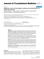
Safety chapter
2
Safety chapter
Explanation of the safety information
Warning signs denoting different types of
danger
The following signal words are used in these operating instructions to
identify different severities of a hazard:
Signal word
Meaning
WARNING
Denotes a possibly hazardous sit‐
uation. If this is disregarded, you
are in a life-threatening situation
and this can result in serious inju‐
ries.
CAUTION
Denotes a possibly hazardous sit‐
uation. If this is disregarded, it
could result in slight or minor inju‐
ries or material damage.
The following warning signs are used in these operating instructions to
denote different types of danger:
Warning signs
Type of danger
Warning – high-voltage.
Warning – danger zone.
Correct and proper use
n
n
n
n
n
n
n
n
n
n
n
8
The pump may only be used to dose liquid metering chemicals.
Only SST design pumps may be used with combustible feed chemi‐
cals.
The pump may only be started up after it has been correctly installed
and commissioned in accordance with the technical data and specifi‐
cations contained in the operating instructions.
The general limitations with regard to viscosity limits, chemical resist‐
ance and density must be observed - see also ProMinent resistance
list (In the product catalogue or at www.prominent.com)!
Any other uses or modifications are prohibited.
The pump is not intended for the metering of gaseous media or solids.
The pump is not intended for operation in hazardous locations.
The pump is not intended for exterior applications without use of suit‐
able protective equipment.
The pump should only be operated by trained and authorised per‐
sonnel, see the following "Qualifications" table.
You are obliged to observe the information contained in the operating
instructions at the different phases of the device's service life.
Safety chapter
Safety information
WARNING!
Warning of hazardous or unknown feed chemical
Should a hazardous or unknown feed chemical be used, it
may escape from the hydraulic components when working
on the pump.
–
–
Take appropriate protective measures before working on
the pump (protective eyewear, protective gloves, ...).
Read the safety data sheet on the feed chemical.
Drain and flush the liquid end before working on the
pump.
CAUTION!
Warning of feed chemical spraying around
Feed chemical can spray out of the hydraulic components if
they are manipulated or opened due to pressure in the liquid
end and adjacent parts of the system.
–
–
Disconnect the pump from the mains power supply and
ensure that it cannot be switched on again by unauthor‐
ised persons.
Depressurise the system before commencing any work
on hydraulic parts.
CAUTION!
Warning of feed chemical spraying around
An unsuitable feed chemical can damage the parts of the
pump contacted by the chemical.
–
Take into account the resistance of the material con‐
tacted by the chemical when selecting the feed chemical
- refer to the ProMinent ® resistance list in the product
equipment catalogue or at www.prominent.com.
CAUTION!
Danger of personal and material damage
The use of untested third party parts can result in damage to
personnel and material damage.
–
Only fit parts to dosing pumps, which have been tested
and recommended by ProMinent.
CAUTION!
Danger from incorrectly operated or inadequately maintained
pumps
Danger can arise from a poorly accessible pump due to
incorrect operation and poor maintenance.
–
–
Ensure that the pump is accessible at all times.
Adhere to the maintenance intervals.
CAUTION!
Warning of illegal operation
Observe the regulations that apply where the unit is to be
installed.
9
Safety chapter
Information in the event of an emergency
In the event of an electrical accident, disconnect the mains cable from the
mains or press the emergency cut-off switch fitted on the side of the
system!
If feed chemical escapes, also depressurise the hydraulic system around
the pump as necessary. Adhere to the safety data sheet for the feed
chemical.
Qualification of personnel
Activity
Qualification level
Storage, transport, unpacking
Instructed person
Assembly, installation of hydraulic
system
Technical personnel, service
Installation, electrical
Electrical technician
Operation
Instructed person
Maintenance, repair
Technical personnel, service
Decommissioning, disposal
Technical personnel, service
Troubleshooting
Technical personnel, electrical
technician, instructed person,
service
Explanation of the terms:
Technical personnel
A qualified employee is deemed to be a person who is able to assess the
tasks assigned to him and recognise possible dangers based on his/her
technical training, knowledge and experience, as well as knowledge of
pertinent regulations.
Note:
A qualification of equal validity to a technical qualification can also gained
by several years employment in the relevant work area.
Electrical technician
Electrical technicians are deemed to be people, who are able to complete
work on electrical systems and recognize and avoid possible dangers
independently based on their technical training and experience, as well as
knowledge of pertinent standards and regulations.
Electrical technicians should be specifically trained for the working envi‐
ronment in which the are employed and know the relevant standards and
regulations.
Electrical technicians must comply with the provisions of the applicable
statutory directives on accident prevention.
Instructed person
An instructed person is deemed to be a person who has been instructed
and, if required, trained in the tasks assigned to him/her and possible dan‐
gers that could result from improper behaviour, as well as having been
instructed in the required protective equipment and protective measures.
Customer Service department
Customer Service department refers to service technicians, who have
received proven training and have been authorised by ProMinent or Pro‐
Maqua to work on the system.
Sound pressure level
Sound pressure level LpA < 70 dB in accordance with EN ISO
20361:2010-10
at maximum stroke length, maximum stroke rate, maximum back pressure
(water)
10
Storage, transport and unpacking
3
Storage, transport and unpacking
Safety information
WARNING!
Only return metering pumps for repair in a cleaned state and
with a flushed liquid end - refer to the section on decommis‐
sioning!
Only send metering pumps with a filled in Decontamination
Declaration form. The Decontamination Declaration consti‐
tutes an integral part of an inspection / repair order. A unit
can only be inspected or repaired when a Declaration of
Decontamination Form is submitted that has been completed
correctly and in full by an authorised and qualified person on
behalf of the pump operator.
The "Decontamination Declaration Form" can be found in the
Appendix or at www.prominent.com.
CAUTION!
Danger of material damage
The device can be damaged by incorrect or improper storage
or transportation!
–
–
–
Scope of supply
Compare the delivery note with the scope of supply:
n
n
n
n
Storage
The unit should only be stored or transported in a well
packaged state - preferably in its original packaging.
The packaged unit should also only be stored or trans‐
ported in accordance with the stipulated storage condi‐
tions.
The packaged unit should be protected from moisture
and the ingress of chemicals.
Metering pump with mains power cable
If necessary, connector kit for hose/pipe connection
Product-specific operating instructions with EC Declaration of Con‐
formity and supplementary information CD for ProMinent pump oper‐
ating instructions.
As necessary, documents for options and accessories
Personnel:
n
Technical personnel
1.
Place the caps on the valves.
3.
Preferably place the pump standing vertically on a pallet and secure
against falling over.
4.
Cover the pump with a tarpaulin cover - allowing rear ventilation.
Store the pump in a dry, closed shop under the following ambient condi‐
tions.
11
Storage, transport and unpacking
Ambient conditions
Data
Minimum storage and transport tempera‐
ture
-10 °C
Maximum storage and transport tempera‐
ture
+50 °C
Maximum air humidity *
* non-condensing
12
Value Unit
95 % rel.
humidity
Overview of equipment and control elements
4
Overview of equipment and control elements
Overview of equipment
1
2
5
3
6
4
P_SI_0067_SW
Fig. 1: Overview of equipment S1Ca
1
2
3
4
Drive motor
Drive unit
Control unit
Liquid end
Control elements
1
2
P_SI_0088_SW
Fig. 2: Sigma control elements
1
2
Relief valve
Diaphragm rupture sensor (visual)
13
Overview of equipment and control elements
1
2
43
5
10
9
8
7
6
P_SI_0079_SW
Fig. 3: Block diagram Sigma Control 1
1
2
3
4
5
6
7
8
9
10
Stroke adjustment dial
LCD screen
Operating indicator (green)
Warning indicator (yellow)
Fault indicator (red)
i [key ]
[START/STOP] key
[P] key
[DOWN] key
[UP] key
1
2
3
4
5
6
7
P_SI_0078_SW
Fig. 4: Block diagram Sigma Control 2
1
2
3
4
5
6
7
14
Mains switch
"Diaphragm rupture" terminal
Mains Cable
"External control" terminal
"Dosing monitor" terminal
"Level Switch" terminal
Relay cable
Functional description
5
Functional description
5.1 Drive unit
The metering pump is an diaphragm pump, the stroke length of which can
be adjusted. An electric motor (1) drives the pump. A worm gear (2) steps
down its drive rotation A cam (3), in conjunction with the uptake fork (8)
converts this into an oscillation movement of the slide rod (4). A return
spring (5) presses the uptake fork together with the slide rod positively
against the cam thus producing the reciprocal stroke. The stroke length
can be adjusted using the stroke adjustment dial (6) and the axle (7). The
different stroke lengths are in effect caused by a limitation of the reciprocal
strokes (see Ä “Illustration of the stroke movement” on page 15). The
slide rod transmits the stoke motion to the metering diaphragms.
4
5
1
3
8
7
6
P_SI_0018_SW
Fig. 5: Section through the drive unit Sigma 1
1
2
3
4
5
6
7
8
Illustration of the stroke movement
Electric motor
Worm gear (not visible)
Eccentric cam
Slide rod
Return spring
Stroke adjustment dial
Axle
Uptake fork
a)
b)
s
s
ω
0
180
360
ω
0
180
360
P_PL_0009_SW
Fig. 6: Stroke movement at a) maximum stroke length and b) reduced
stroke length.
s
⍵
+
-
Stroke velocity
Cam rotational angle
Discharge stroke
Suction stroke
15
Functional description
5.2 Liquid end
The diaphragm (2) hermetically shuts off the pump volume of the dosing
head (4) towards the outside. The suction valve (1) closes as soon as the
diaphragm (2) is moved in to the dosing head (4) and the feed chemical
flows through the discharge valve (3) out of the dosing head. The dis‐
charge valve (3) closes as soon as the diaphragm (2) is moved in the
opposite direction due to the vacuum pressure in the dosing head and
fresh feed chemical flows through the suction valve (1) into the dosing
head. One cycle is thus completed.
3
4
5
13
2
1
Fig. 7: Cross-section through the liquid end
1
2
3
4
5
13
Suction valve
Diaphragm
Discharge valve
Dosing head
Backplate
Safety diaphragm
5.3 Integral relief valve
The integral relief valve normally operates as a simple, directly controlled
bleeder valve. As soon as the pressure exceeds the pressure value, which
is set using the large spring (1), it lifts the ball (2). The feed chemical then
flows out through the hose connection (5), e.g. into a storage tank.
The integral relief valve can only protect the motor and the gear, and then
only against impermissible positive pressure that is caused by the
metering pump itself. It cannot protect the system against positive pres‐
sure.
The integral relief valve works as a bleed valve if the rotary dial (3) is
turned clockwise up to the "open" stop: This relieves the high force caused
by the large spring (1) which was acting on the ball (2) - the ball is now
controlled by the low force of the small spring (4). The integral relief valve
is, when used in this way, a priming aid for starting up the pump against
pressure.
16
Functional description
1
2
3
4
5
P_SI_0019
Fig. 8: Integral relief valve
1
2
3
4
5
Spring, large
Ball
Rotary dial
Spring, small
Hose connection
5.4 Multi-layer safety diaphragm
The multi-layer safety diaphragm has the same function as the conven‐
tional double diaphragm system with working and safety diaphragms; how‐
ever it also has the advantage that both diaphragms are joined together in
a single unit.
If the working layer (1) breaks, the feed chemical penetrates between the
working and safety (2) layers and spreads out. The safety layer ensures
that not feed chemical penetrates to the outside.
As soon as the feed chemical reaches the flap (3) on the edge of the multilayer safety diaphragm, it inflates it. The flap presses a piston (4) in the
membrane rupture sensor (5), so that this triggers.
With the visual diaphragm rupture sensor, the lowered red cylinder (6)
springs forward beneath the transparent cover (7) so that it then becomes
clearly visibleFig. 9.
With the electrical diaphragm rupture sensor, a switch is switched. A con‐
nected signalling device must signal the diaphragm rupture.
Fig. 9: Visual diaphragm rupture sensor, triggered and untriggered
The electrical diaphragm rupture sensor is connected to the "diaphragm
rupture indicator" terminal. If a diaphragm rupture occurs, the red LED
“Fault” indicator illuminates on the pump, the identifier “Error” and
“DIAPH” flash on the LCD screen. Dependent on the identity code variant
selected under "Displacement body", the pump either continues metering
( “Pump emits alarm” ) or stops ( “Pump stops” ).
17
Functional description
1
7
6
5
4
2
3
P_SI_0020_SW
Fig. 10: Section through the Sigma diaphragm rupture warning system
("Visual break indicator" version)
1
2
3
4
5
6
7
Working layer (≙ operating diaphragm)
Safety layer (≙ safety diaphragm)
Flap
Piston
Diaphragm rupture sensor
Cylinder, red
Cover, transparent
5.5 Operating modes
The operating modes are selected via the “MODE” menu (dependent on
the identity code, some operating modes may not be present):
“Analog” operating mode (Identity code, control variant: analog). The
stroke rate is controlled using an analog current signal via the "External
control" terminal Processing of the current signal can be preselected via
the control unit.
“Manual” operating mode The stroke rate is set manually via the control
unit. 100 % corresponds to 180 strokes/min.
“Contact” operating mode: This operating mode provides the option of
making fine adjustments using small scaling or transfer factors. The
metering can be triggered either by a pulse received via the "External con‐
trol" terminal or through a contact or a semiconductor switching element. A
metering quantity (batch) or a number of strokes (scaling or transfer factor
0.01 to 99.99) can be pre-selected via the control unit using the "Pulse
Control" option.
“Batch” operating mode: This operating mode provides the option of
working with large transfer factors (up to 65535). The metering can be trig‐
gered either by pressing the [P] key or by a pulse received via the
"External control" terminal or through a contact or a semiconductor
switching element. It is possible to pre-select a metering quantity (batch)
or a number of strokes via the control unit.
“BUS” operating mode (Identity code, control variant: CANopen or PRO‐
FIBUS® This operating mode provides the option of controlling the pump
via a BUS (see “Supplementary instructions for ProMinent® gamma/ L and
ProMinent Sigma versions with PROFIBUS®".
18
Functional description
5.6 Functions
The following functions can be selected using the SET menu:
"Calibrate" function: (Identity code, stroke length adjustment: manual +
calibration) The pump can also be operated in the calibrated state in all
operating modes. In this case, the corresponding continuous displays can
then indicate the metering volume or the capacity directly. Calibration is
maintained within a stroke rate range of 0 - 180 strokes/min. The calibra‐
tion is also maintained when the stroke length is altered by up to ±10 %
scale divisions.
"Auxiliary frequency" function: Enables a freely selectable and program‐
mable stroke rate to be switched on in the “SET” menu, which can be
controlled via the "External Control" terminal. This auxiliary frequency has
priority over the operating mode stroke rate settings .
"Flow" function: Stops the pump when the flow is insufficient, provided a
dosing monitor is connected. The number of defective strokes, after which
the pump is switched off, can be set in the “SET” menu.
The following functions are available as standard:
"Level switch" function: Information about the liquid level in the chemical
feed container is reported to the pump control. To do so, a two-stage level
switch must be fitted; it is connected to the "Level switch" terminal.
"Pause" function: The pump can be remotely stopped via the "External
Control" terminal. The "Pause" function only works via the "External Con‐
trol" terminal.
The following functions are triggered by a key press:
"Stop" function: The pump can be stopped without disconnecting it from
the power supply by pressing the [STOP/START] key.
"Prime" function: Priming (short-term transport at maximum frequency) can
be triggered by simultaneous pressing of the two arrow keys in the "Stroke
rate" continuous display.
5.7 Options
Relay option
The pump has two connecting options (not with PROFIBUS® or timer):
Option "Fault indicating relay" or "Power relay": In the event of fault sig‐
nals, warning signals or tripped level switches, the relay connects to com‐
plete an electric circuit (for alarm horns etc.). The relay can be retrofitted
via a knock-out in the drive unit.
"Fault indicating and pacing relay" option In addition to the fault indicating
relay, the pacing relay can be used to make a contact every stroke. The
relay can be retrofitted via a knock-out in the drive unit.
19
Functional description
5.8 Function and fault Indicator
The operating and fault statuses are indicated by the three LED indicators
and the “Error” identifier on the LCD screen, see also the "Trouble‐
shooting" chapter.
5.9 LCD screen
If a fault occurs, the identifier “Error” appears and an additional error mes‐
sage.
5.10
LED indicators
Operating indicator (green): The operating indicator illuminates if during
pump operation there are no incoming fault or warning messages. It goes
out briefly with every stroke.
Warning indicator (yellow): The warning indicator illuminates, if the pump
electronics detect a condition which may lead to a fault, e.g. "liquid level
low 1st stage".
Fault indicator (red): The fault indicator illuminates, if a fault occurs e.g.
liquid level low 2nd stage".
5.11
Hierarchy of operating modes, functions and fault statuses
The different operating modes, functions and fault statuses have a dif‐
ferent effect on if and how the pump reacts.
The following list shows the order:
1. - Priming
2. - Fault, Stop, Pause
3. - Auxiliary frequency (external frequency changeover)
4. - Manual, external contact
Comments:
re 1 - "Priming" can take place in any mode of the pump (providing it is
functioning).
re 2 - "Fault", "Stop" and "Pause" stop everything apart from "Priming".
re 3 - The stroke rate of "Auxiliary rate" always has priority over the
stroke rate specified by an operating mode or priority 4.
20
Assembly
6
Assembly
CAUTION!
Danger of material damage
The device can be damaged by incorrect or improper storage
or transportation!
–
–
–
The unit should only be stored or transported in a well
packaged state - preferably in its original packaging.
The packaged unit should also only be stored or trans‐
ported in accordance with the stipulated storage condi‐
tions.
The packaged unit should be protected from moisture
and the ingress of chemicals.
CAUTION!
Warning about personal and material damage
Personal and material damage may be caused if the unit is
operated outside of the permissible ambient conditions.
–
Please observe the permissible ambient conditions refer to the chapter entitled "Technical Data".
Supporting floor
WARNING!
Risk of electric shock
If water or other electrically conducting liquids penetrate into
the drive housing, an electric shock may occur.
–
h
Position the pump so that drive housing cannot be
flooded.
P_MOZ_0016_SW
Fig. 11
WARNING!
The pump can break through the supporting floor or slide off
it
– The supporting floor must be horizontal, smooth and per‐
manently load-bearing.
Capacity too low
Vibrations can disturb the valves of the liquid end.
–
The supporting floor must not vibrate.
21
Assembly
Space requirement
CAUTION!
Danger from incorrectly operated or inadequately maintained
pumps
Danger can arise from a poorly accessible pump due to
incorrect operation and poor maintenance.
A
–
–
A
Ensure that the pump is accessible at all times.
Adhere to the maintenance intervals.
Position the pump so that control elements such as the stroke length
adjustment knob, the indicating dial A or the oil inspection window are
accessible.
P_MOZ_0018_SW
Fig. 12
In so doing, ensure there is enough space to carry out an oil change (vent
screws, oil drain plugs, oil trough ...).
1
2
3
1
f
2
Ensure there is sufficient free space (f) around the dosing head as well as
the suction and discharge valve so that maintenance and repair work can
be carried out on these components.
f
f
Discharge valve
Dosing head
Suction valve
3
P_MOZ_0017_SW
Fig. 13
Liquid end alignment
Capacity too low
If the valves of the liquid end do not stand upright, they
cannot close correctly.
–
The discharge valve must be upright.
Fastening
Capacity too low
Vibrations can disturb the valves of the liquid end.
–
m
DN
m
P_MOZ_0015_SW
Fig. 14
22
Secure the metering pump so that no vibrations can
occur.
Take the dimensions (m) for the fastening holes from the appropriate
dimensional drawings or data sheets.
Fasten the pump base to the supporting floor using suitable screws.
Installation
7
Installation
CAUTION!
Danger of personnel injury and material damage
The disregard of technical data during installation may lead
to personal injuries or damage to property.
–
Observe the technical data- refer to chapter "Technical
Data" and, where applicable, the operating instructions
of the accessories.
7.1 Installation, hydraulic
WARNING!
Warning of feed chemical reactions to water
Feed chemicals that should not come into contact with water
may react to residual water in the liquid end that may origi‐
nate from works testing.
–
–
Blow the liquid end dry with compressed air through the
suction connector.
Then flush the liquid end with a suitable medium through
the suction connector.
WARNING!
The following measures are an advantage when working with
highly aggressive or hazardous feed chemicals:
–
–
Install a bleed valve with recirculation in the storage
tank.
Install an additional shut-off valve on the discharge or
suction ends.
CAUTION!
Warning about personal and material damage
Also observe the "General Operating Instructions for ProMi‐
nent ® Motor-Driven Metering Pumps and Hydraulic Accesso‐
ries"!
CAUTION!
Suction problems possible
For feed chemicals with a particle size greater than 0.3 mm,
the valves may no longer close properly.
–
Install a suitable filter in the suction line.
23
Installation
CAUTION!
Warning against the discharge line bursting
With a closed discharge line (e.g. due to a clogged discharge
line or by closing a valve), the pressure that the metering
pump generates can reach several times the permissible
pressure of the system or the metering pump. This could
lead to lines bursting resulting in dangerous consequences
with aggressive or toxic feed chemicals.
–
Install a relief valve that limits the pressure of the pump
to the maximum permissible operating pressure of the
system.
CAUTION!
Warning against bursting of the suction or discharge lines
Hose lines with insufficient pressure rating may burst.
–
Only use hose lines with the required pressure rating.
CAUTION!
Warning against lines disconnecting
With suction, discharge and relief lines installed incorrectly
can loosen / disconnect from the pump connection.
–
–
–
Only use original hoses with the specified hose diameter
and wall thickness.
Only use clamping rings and hose nozzles that corre‐
spond with the respective hose diameter.
Always connect the lines without mechanical tension.
CAUTION!
Warning against leaks
Leaks can occur on the pump connection depending on the
insert used.
–
P_SI_0021
Fig. 15: Moulded composite seals with
corrugated insert
–
The pump is supplied with PTFE moulded composite
seals with a flare, which are used for the pump connec‐
tions. They seal the connections between grooved pump
valves and the grooved inserts from ProMinent - see
Fig. 15.
In the event that an unflared insert is used (e.g. third
party part), an elastomer flat seal must be used - see
Fig. 16.
Numerous installation instructions with drawings are con‐
tained in the "General Operating Instructions for ProMinent®
metering pumps and hydraulic accessories".
P_SI_0022
Fig. 16: Elastomer flat seal with an insert
without flare
24
–
–
Precise metering is only possible when the back pres‐
sure is maintained above 1 bar at all times.
If metering at atmospheric pressure, a back pressure
valve should be used to create a back pressure of
approx. 1.5 bar.
Installation
CAUTION!
Warning of backflow
A back pressure valve, spring-loaded injection valve, relief
valve, foot valve or a liquid end do not represent absolutely
leak-tight closing elements.
–
For this purpose use a shut-off valve, a solenoid valve or
a vacuum breaker.
CAUTION!
Warning of illegal operation
Observe the regulations that apply where the unit is to be
installed.
CAUTION!
To check the pressure conditions in the piping system it is
recommended that connecting options are provided for a
manometer close to the suction and pressure connector.
1
2
3
1
2
3
4
5
Manometer socket
Discharge line (pipe)
Discharge valve
Suction valve
Suction line (pipe)
4
1
CAUTION!
Connect the pipelines to the pump so that no residual forces
act on the pump, e.g. due to the offsetting, weight or expan‐
sion of the line.
5
P_MOZ_0020_SW
Fig. 17: Manometer connecting options
1
2
Only connect steel or stainless steel piping via a flexible
piping section to a plastic liquid end.
1
2
3
Steel pipeline
Flexible pipe section
Plastic liquid end
3
P_MOZ_0021_SW
Fig. 18: Steel pipeline at the liquid end
Integral relief valve
CAUTION!
Danger due to incorrect use of the integral relief valve
The integral relief valve can only protect the motor and the
gear, and then only against impermissible positive pressure
that is caused by the metering pump itself. It cannot protect
the system against positive pressure.
–
–
Protect the motor and gear of the system against posi‐
tive pressure using other mechanisms.
Protect the system against illegal positive pressure using
other mechanisms.
25