conductivity e+h smartec s cld134
Bạn đang xem bản rút gọn của tài liệu. Xem và tải ngay bản đầy đủ của tài liệu tại đây (2.78 MB, 88 trang )
Operating Instructions
Smartec S CLD134
Conductivity Measuring System
R
Standard Number 74-03
BA401C/07/en/01.08
71066353
Software version 1.13 or later
Brief overview
This overview explains how to use these Operating Instructions to commission your measuring
system quickly and safely.
Safety instructions
→ Page 5 ff.
→ Page 6 ff.
General safety instructions
Explanation of the warning symbols
You can find special instructions at the appropriate position in the chapter in question. The
significance is indicated with the icons Warning #, Caution " and Note !.
Ỉ
Installation
→ Page 12 ff.
→ Page 19 ff.
Here, you can find information on installation conditions and the dimensions of the measuring
system.
These pages explain how to install the measuring system
Ỉ
Wiring
→ Page 22 ff.
Here, you can find out how to connect your measuring system.
You also find information on how to connect the CLS54 sensor if you are using a separate
version.
Ỉ
Operation
→
→
→
→
Page 28
Page 31
Page 38 ff.
Page 56 ff.
The display and operating elements are described here.
The operating concept is described here.
The system configuration is explained here.
You can find information on how to calibrate the sensor here.
Ỉ
Maintenance
→
→
→
→
Page 59 ff.
Page 64 ff.
Page 66 ff.
Page 72 ff.
Here, you can find information on the maintenance of the measuring point.
Accessories which can be supplied for the measuring system are listed on the pages indicated.
Use the trouble-shooting information given here if your system should not work properly.
Spare parts that can be delivered and a system overview are listed on these pages.
Ỉ
Technical data
→ Page 78
→ Page 78 ff.
Dimensions
Process conditions, weight, material
Ỉ
Index
→ Page 84 ff.
The index helps you to find information and important terms easily and quickly.
Endress+Hauser
Smartec S CLD134
Table of contents
1
Safety instructions . . . . . . . . . . . . . . . . 5
6
Commissioning . . . . . . . . . . . . . . . . . . 33
1.1
1.2
1.3
1.4
1.5
Designated use . . . . . . . . . . . . . . . . . . . . . . . . . . . .
Installation, commissioning and operation . . . . . . . .
Operational safety . . . . . . . . . . . . . . . . . . . . . . . . . .
Return . . . . . . . . . . . . . . . . . . . . . . . . . . . . . . . . . . .
Notes on safety conventions and symbols . . . . . . . . .
6.1
6.2
6.3
6.4
2
Identification . . . . . . . . . . . . . . . . . . . . 7
2.1
2.2
2.3
Device designation . . . . . . . . . . . . . . . . . . . . . . . . . 7
2.1.1 Nameplate . . . . . . . . . . . . . . . . . . . . . . . . . 7
2.1.2 Product structure Smartec S CLD134 . . . . . 8
2.1.3 Basic version and function extensions . . . . . 9
Scope of delivery . . . . . . . . . . . . . . . . . . . . . . . . . . . 9
Certificates and approvals . . . . . . . . . . . . . . . . . . . 10
3
Installation . . . . . . . . . . . . . . . . . . . . . 11
3.1
6.5
7
Maintenance . . . . . . . . . . . . . . . . . . . . 59
7.1
3.5
Quick installation guide . . . . . . . . . . . . . . . . . . . . .
3.1.1 Measuring system . . . . . . . . . . . . . . . . . . .
Incoming acceptance, transport, storage . . . . . . . . .
Installation conditions . . . . . . . . . . . . . . . . . . . . . .
3.3.1 Notes on installation . . . . . . . . . . . . . . . . .
3.3.2 CLD134 separate version . . . . . . . . . . . . . .
3.3.3 CLD 134 compact version . . . . . . . . . . . . .
Installation instructions . . . . . . . . . . . . . . . . . . . . .
3.4.1 Mounting CLD134 separate version . . . . . .
3.4.2 Mounting CLD134 compact version or
CLS54 sensor for separate version . . . . . . .
Post-installation check . . . . . . . . . . . . . . . . . . . . . .
Function check . . . . . . . . . . . . . . . . . . . . . . . . . . .
Start-up . . . . . . . . . . . . . . . . . . . . . . . . . . . . . . . . .
Quick setup . . . . . . . . . . . . . . . . . . . . . . . . . . . . . .
Instrument configuration . . . . . . . . . . . . . . . . . . . .
6.4.1 Setup 1 (conductivity, concentration) . . . . .
6.4.2 Setup 2 (temperature) . . . . . . . . . . . . . . . .
6.4.3 Current outputs . . . . . . . . . . . . . . . . . . . . .
6.4.4 Alarm . . . . . . . . . . . . . . . . . . . . . . . . . . . .
6.4.5 Check . . . . . . . . . . . . . . . . . . . . . . . . . . . .
6.4.6 Relay configuration . . . . . . . . . . . . . . . . . .
6.4.7 Temperature compensation with table . . . .
6.4.8 Concentration measurement . . . . . . . . . . .
6.4.9 Service . . . . . . . . . . . . . . . . . . . . . . . . . . .
6.4.10 E+H Service . . . . . . . . . . . . . . . . . . . . . . .
6.4.11 Interfaces . . . . . . . . . . . . . . . . . . . . . . . . . .
6.4.12 Determining the temperature coefficient . .
6.4.13 Remote parameter set switching
(measuring range switching, MRS) . . . . . . .
6.4.14 Calibration . . . . . . . . . . . . . . . . . . . . . . . .
Communication interfaces . . . . . . . . . . . . . . . . . . .
4
Wiring . . . . . . . . . . . . . . . . . . . . . . . . 22
4.1
7.3
4.2
4.3
Electrical connection . . . . . . . . . . . . . . . . . . . . . . .
4.1.1 Electrical connection of transmitter . . . . . .
Alarm contact . . . . . . . . . . . . . . . . . . . . . . . . . . . .
Post-connection check . . . . . . . . . . . . . . . . . . . . . .
Maintenance of Smartec S CLD134 . . . . . . . . . . . .
7.1.1 Dismantling Smartec S CLD134 . . . . . . . . .
7.1.2 Replacement of central module . . . . . . . . .
Maintenance of measuring system . . . . . . . . . . . . .
7.2.1 Cleaning conductivity sensors . . . . . . . . . .
7.2.2 Checking inductive conductivity sensors . .
7.2.3 Instrument check by medium simulation . .
7.2.4 Checking line extension and junction box .
Service equpipment "Optoscope" . . . . . . . . . . . . . .
8
Accessories . . . . . . . . . . . . . . . . . . . . . 64
5
Operation . . . . . . . . . . . . . . . . . . . . . . 28
5.1
5.2
Quick operation guide . . . . . . . . . . . . . . . . . . . . . .
Display and operating elements . . . . . . . . . . . . . . .
5.2.1 Display . . . . . . . . . . . . . . . . . . . . . . . . . . .
5.2.2 Operating elements . . . . . . . . . . . . . . . . . .
5.2.3 Key assignment . . . . . . . . . . . . . . . . . . . . .
Local operation . . . . . . . . . . . . . . . . . . . . . . . . . . .
5.3.1 Operating concept . . . . . . . . . . . . . . . . . . .
8.1
8.2
8.3
8.4
8.5
8.6
8.7
Sensors . . . . . . . . . . . . . . . . . . . . . . . . . . . . . . . . .
Extension cable . . . . . . . . . . . . . . . . . . . . . . . . . . .
Junction box . . . . . . . . . . . . . . . . . . . . . . . . . . . . .
Post mounting kit . . . . . . . . . . . . . . . . . . . . . . . . .
Software upgrade . . . . . . . . . . . . . . . . . . . . . . . . . .
Calibration solutions . . . . . . . . . . . . . . . . . . . . . . .
Optoscope . . . . . . . . . . . . . . . . . . . . . . . . . . . . . . .
9
Troubleshooting . . . . . . . . . . . . . . . . . 66
9.1
9.2
9.3
9.4
9.5
Troubleshooting instructions . . . . . . . . . . . . . . . . .
System error messages . . . . . . . . . . . . . . . . . . . . . .
Process-specific errors . . . . . . . . . . . . . . . . . . . . . .
Instrument-specific errors . . . . . . . . . . . . . . . . . . .
Spare parts . . . . . . . . . . . . . . . . . . . . . . . . . . . . . . .
9.5.1 Exploded view . . . . . . . . . . . . . . . . . . . . . .
9.5.2 Spare part kits . . . . . . . . . . . . . . . . . . . . . .
Return . . . . . . . . . . . . . . . . . . . . . . . . . . . . . . . . . .
Disposal . . . . . . . . . . . . . . . . . . . . . . . . . . . . . . . . .
Software history . . . . . . . . . . . . . . . . . . . . . . . . . . .
3.2
3.3
3.4
5.3
5
5
5
5
6
11
11
12
12
12
14
17
19
19
21
21
22
22
26
27
28
28
28
29
29
31
31
7.2
9.6
9.7
9.8
Endress+Hauser
33
33
35
38
38
39
41
42
43
44
46
47
50
52
52
53
53
56
58
59
59
60
61
61
61
62
63
63
64
64
64
65
65
65
65
66
66
67
70
72
73
74
75
75
75
3
Smartec S CLD134
10
Technical Data. . . . . . . . . . . . . . . . . . . 76
10.1
10.2
10.3
10.4
10.5
10.6
10.7
10.8
10.9
Input . . . . . . . . . . . . . . . . . . . . . . . . . . . . . . . . . . .
Output . . . . . . . . . . . . . . . . . . . . . . . . . . . . . . . . .
Power supply . . . . . . . . . . . . . . . . . . . . . . . . . . . . .
Performance characteristics . . . . . . . . . . . . . . . . . .
Environment . . . . . . . . . . . . . . . . . . . . . . . . . . . . .
Mechanical construction . . . . . . . . . . . . . . . . . . . .
Measurement data of CLS54 sensor . . . . . . . . . . . .
Process . . . . . . . . . . . . . . . . . . . . . . . . . . . . . . . . .
Chemical durability of CLS54 sensor . . . . . . . . . . .
11
Appendix. . . . . . . . . . . . . . . . . . . . . . . 80
76
76
77
77
77
78
78
78
79
Index . . . . . . . . . . . . . . . . . . . . . . . . . . 84
4
Endress+Hauser
Smartec S CLD134
Safety instructions
1
Safety instructions
1.1
Designated use
Smartec S CLD134 is a field-tested and reliable transmitter used to determine the conductivity of
liquid media.
It is particularly suitable for use in the foodstuffs industry.
Any other use than the one described here compromises the safety of persons and the entire
measuring system and is, therefore, not permitted.
The manufacturer is not liable for damage caused by improper or non-designated use.
1.2
Installation, commissioning and operation
Please note the following items:
• Installation, commissioning, operation and maintenance of the measuring system must only be
carried out by trained technical personnel.
The technical personnel must be authorized for the specified activities by the system operator.
• Electrical connection must only be carried out by a certified electrician.
• Technical personnel must have read and understood these Operating Instructions and must
adhere to them.
• Before commissioning the entire measuring point, check all the connections for
correctness. Ensure that electrical cables and hose connections are not damaged.
• Do not operate damaged products and secure them against unintentional
commissioning. Mark the damaged product as being defective.
• Measuring point faults may only be rectified by authorized and specially trained
personnel.
• If faults can not be rectified, the products must be taken out of service and secured against
unintentional commissioning.
• Repairs not described in these Operating Instructions may only be carried out at the
manufacturer’s or by the service organization.
1.3
Operational safety
The transmitter has been designed and tested according to the state of the art and left the factory in
perfect functioning order.
Relevant regulations and European standards have been met.
As the user, you are responsible for complying with the following safety conditions:
• Installation instructions
• Local prevailing standards and regulations.
Immunity to interference
This instrument has been tested for electromagnetic compatibility in industrial use according to
applicable European standards.
Protection against interference as specified above is valid only for an instrument
connected according to the instructions in these Operating Instructions.
1.4
Return
If the transmitter has to be repaired, please return it cleaned to the sales center responsible. Please
add a detailed failure description. If the failure diagnosis is not clear please send also the cable and
the sensor.
Please use the original packaging, if possible.
Please enclose the completed "Declaration of Hazardous Material and De-Contamination" (copy the
second last page of these Operating Instructions) with the packaging and also the shipping
documents.
Endress+Hauser
5
Safety instructions
Smartec S CLD134
1.5
Notes on safety conventions and symbols
Safety symbols
#
"
!
Warning!
This symbol alerts you to hazards. They can cause serious damage to the instrument or to persons
if ignored.
Caution!
This symbol alerts you to possible faults which could arise from incorrect operation. They could
cause damage to the instrument if ignored.
Note!
This symbol indicates important items of information.
Electrical symbols
%
&
)
*
b
Direct Current (DC)
A terminal at which DC is applied or through which DC flows.
Alternating Current (AC)
A terminal at which (sine-form) AC is applied or through which AC flows.
Ground connecting
A terminal, which, from the user’s point of view, is already grounded using a grounding system.
Protective ground terminal
A terminal which must be grounded before other connections may be set up.
Alarm relay
Input
Output
DC voltage source
Temperature sensor
6
Endress+Hauser
Smartec S CLD134
Identification
2
Identification
2.1
Device designation
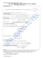
2.1.1
Nameplate
Compare the order code on the nameplate (on the Smartec) with the product structure (see below)
and check that it agrees with your order.
You can identify the instrument variant by the order code on the nameplate. Under "Codes", you
can find the release code for the software upgrade "MRS".
Made in Germany, D-70839 Gerlingen
SMARTEC S conductivity
order code
serial no.
meas. range
temperature
output 1
output 2
mains
CLD134-PMV530AB2
codes 1C466C05 G00
100 µS … 2000 mS/cm
-10 … +125 °C
0/4 … 20 mA
0/4 … 20 mA
230 VAC
50/60 Hz
7.5 VA
prot. class
ambient temp.
/ 8833
HART
IP 67
0 … +55°C
.
131085-4D
a0005491
Fig. 1:
Endress+Hauser
Nameplate CLD134 (example)
7
Identification
Smartec S CLD134
2.1.2
Product structure Smartec S CLD134
Housing
E
P
W
X
S
Transmitter only (without sensor)
Compact version
Separate transmitter, cable length 5 m / 16.41 ft
Separate transmitter, cable length 10 m / 32.81 ft
Separate transmitter, cable length 20 m / 65.62 ft
Process connection
000
MV5
AA5
CS1
SMS
VA4
BC5
Not selected (transmitter only)
Dairy fitting DIN 11851, DN 50a)
Aseptic fitting DIN 11864-1 form A, pipe DIN 11850, DN 50
Clamp ISO 2852, 2" (long)
SMS 2"b)
Varivent® N DN 40 to 125
NEUMO BioControl® D50
Cable entry
3
5
Cable gland M 20 x 1.5
Conduit adapter NPT ½ "
Power supply
0
1
5
8
230 V AC
115 V AC
100 V AC
24 V AC / DC
Current output / communication
AA
AB
HA
HB
PE
PF
PP
Current output conductivity, without communication
Current output conductivity and temperature, without communication
HART, current output conductivity
HART, current output conductivity and temperature
PROFIBUS-PA, no current output
PROFIBUS-PA, M 12 connector, no current output
PROFIBUS-DP, no current output
Additional features
1
2
3
4
5
6
CLD134-
Basic version
Remote parameter set switching
Biological reactivity tests according to USP <87>, <88> class VI
Remote parameter set switching and biological reactivity tests according to
USP <87>, <88> class VI
CRN approval (according to ASME B31.3)c)
CRN approval (according to ASME B31.3)c) + Biological reactivity tests
according to USP <87>, <88> class VI
complete order code
a)
Dairy pipe fitting DIN 11851 is generally not considered hygienic. With the adapter SKS Siersma,
it meets the 3-A standards requirements.
b)
Process connection is not considered hygienic according to the requirements of EHEDG.
c)
CRN approval only valid for process connections MV5, CS1 and VA4.
8
Endress+Hauser
Smartec S CLD134
Identification
2.1.3
Basic version and function extensions
Functions of the basic version
Options and their functions
•
•
•
•
•
•
•
•
•
• Second current output for temperature (hardware
option)
• HART communication
• PROFIBUS communication
Measurement
Calibration of cell constant
Calibration of residual coupling
Calibration of installation factor
Read instrument parameters
Linear current output
Current output simulation
Service functions
Temperature compensation selectable (e.g. 1 free
coefficient table)
• Concentration measurement selectable (4 defined
curves, 1 free table)
• Relay as alarm contact
Remote parameter set switching (software option):
• Remote switching of max. 4 parameter sets
(measuring ranges)
• Temperature coefficients can be determined
• Temperature compensation selectable (e.g. 4 free
coefficient tables)
• Concentration measurement selectable (4 defined
curves, 4 free tables)
• Check of measuring system by PCS alarm (live check)
• Relay can be configured as alarm or limit contact
Biological reactivity according to USP <87>, <88>
class VI
2.2
Scope of delivery
The scope of delivery of the compact version inlcudes:
• Smartec S CLD134 compact measuring system with integrated sensor
• Terminal strip set
• Operating Instructions BA401C/07/en
• Versions with HART communication only:
Operating Instructions Field communication with HART, BA212C/07/en
• Versions with PROFIBUS interface only:
– Operating Instructions Field communication with PROFIBUS, BA213C/07/en
– M12 connector (-******PF* versions only)
The scope of delivery of the separate version includes:
• Smartec S CLD134 transmitter
• CLS54 inductive sensor with fixed cable
• Terminal strip set
• Operating Instructions BA401C/07/en
• Versions with HART communication only:
Operating Instructions Field communication with HART, BA212C/07/en
• Versions with PROFIBUS interface only:
– Operating Instructions Field communication with PROFIBUS, BA213C/07/en
– M12 connector (-******PF* versions only)
The scope of delivery of version "transmitter without sensor" includes:
• Smartec S CLD134 transmitter
• Terminal strip set
• Operating Instructions BA401C/07/en
• Versions with HART communication only:
Operating Instructions Field communication with HART, BA212C/07/en
• Versions with PROFIBUS interface only:
– Operating Instructions Field communication with PROFIBUS, BA213C/07/en
– M12 connector (-******PF* versions only)
Endress+Hauser
9
Identification
Smartec S CLD134
2.3
Certificates and approvals
Declaration of conformity
The product meets the legal requirements of the harmonized European standards. It thus complies
with the legal requirements of the EC directives.
The manufacturer confirms successful testing of the product by affixing the 4 symbol.
FDA
All materials in contact with medium are listet at FDA.
EHEDG
The sensor CLS54 has been certified for in-place cleanability according to EHEDG document 2.
!
Note!
The cleanability of a sensor also depends on the way of installation. To install the sensor in a pipe
system use the appropriate and EHEDG certified flow assembly for the respective process
connection.
3-A
Certified according to 3-A Standard 74-03 ("3-A Sanitary Standards for Sensor and Sensor Fittings
and Connections Used on Milk and Milk Products Equipment").
Biological reactivity (USP class VI) (optional)
Certificate on biological reactivity tests according to USP (United States Pharmacopeia) part <87>
und part <88> class VI with traceability of the materials in contact with medium.
Pressure approval
Canadian pressure approval for pipes according to ASME B31.3
10
Endress+Hauser
Smartec S CLD134
Installation
3
Installation
3.1
Quick installation guide
The following procedure should be followed for a complete measuring point installation:
Compact version:
• Perform an air set. Install the compact version at the measuring point (see chapter "Mounting
CLD134 compact version").
• Connect the compact version as described in the chapter "Electrical connection".
• Start up the compact version as described in the chapter "Commissioning".
Separate version:
• Mount the transmitter (see chapter "Mounting CLD134 separate version").
• If you have not yet installed the sensor at the measuring point, perform an Airset and install the
sensor (see the Technical Information of the sensor).
• Connect the sensor to the Smartec S CLD134 as described in the chapter "Electrical connection".
• Connect the transmitter as described in the chapter "Electrical connection".
• Start up the Smartec S CLD134 as described in the chapter "Commissioning".
3.1.1
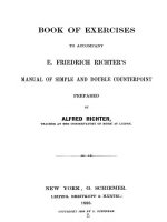
Measuring system
A complete measuring system comprises:
• the Smartec S CLD134 transmitter (separate version)
• the CLS54 conductivity sensor with integrated temperature sensor and fixed cable
or
• the CLD134 compact version with integrated CLS54 conductivity sensor
Optional for the separate version: CLK5 extension cable, VBM junction box, mounting kit for pipe
mounting
B
ENDRESS+HAUSER
SMARTEC S
CAL
+
E
–
ALARM
A
C
a0005438
Fig. 2:
A
B
C
Endress+Hauser
Complete measuring systems Smartec S CLD134 as separate transmitter and compact version
CLS54 conductivity sensor
Smartec S CLD134 transmitter
Smartec S CLD134 compact version with integrated CLS54
11
Installation
Smartec S CLD134
3.2
Incoming acceptance, transport, storage
• Make sure the packaging is undamaged!
Inform the supplier about damage to the packaging. Keep the damaged packaging until the matter
has been settled.
• Make sure the contents are undamaged!
Inform the supplier about damage to the delivery contents. Keep the damaged products until the
matter has been settled.
• Check that the scope of delivery is complete and agrees with your order and the shipping
documents.
• The packaging material used to store or to transport the product must provide shock protection
and humidity protection. The original packaging offers the best protection. Also, keep to the
approved ambient conditions (see "Technical data").
• If you have any questions, please contact your supplier or your sales center responsible.
3.3
Installation conditions
3.3.1
Notes on installation
Installation positions
The sensor has to be immersed completely into the media. Avoid bubbles in the area of the sensor.
!
Note!
For use in hygienic applications only use materials that comply with 3-A standards 74-03 and the
FDA requirements. The cleanability of a sensor also depends on the way of installation. To install
the sensor in a pipe system use the appropriate and EHEDG certified flow assembly for the
respective process connection.
A
a0005442
Fig. 3:
A
Installation positions of conductivity sensors
Not for hygienic applications
Air set
Perform an air set before sensor installation (see chapter "Calibration"). Make sure that the
instrument is ready for operation, i.e. mains and sensor are connected.
12
Endress+Hauser
Smartec S CLD134
Installation
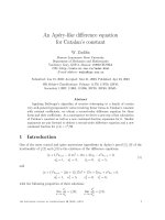
Wall distance
The sensor’s distance from the pipe wall affects the measuring accuracy (see Fig. 5).
a
In narrow installation conditions, the ion flow
in the medium is affected by the pipe walls.
This effect is compensated by the so-called
installation factor.
When the distance from the wall is sufficient,
i.e. a > 15 mm / 0.59", the installation factor
can be ignored (f = 1.00). When the wall
distance is lower, the installation factor
increases in the case of electrically insulating
pipes (f > 1) while it decreases for electrically
conductive pipes (f < 1); see Fig. 5.
The determination of the installation factor is
described in the chapter "Calibration".
a0005440
Fig. 4:
a
Installation of CLD134
Wall distance
f
1.40
2
1.20
1.00
1
0.80
0
5
10
15
20
0.20
0.39
0.59
0.79
25
a [mm]
0.98 a [inch]
a0005441
Fig. 5:
1
2
Endress+Hauser
Relationship between installation factor and distance from wall a
Electrically conductive pipe wall
Insulating pipe wall
13
Installation
Smartec S CLD134
3.3.2
CLD134 separate version
160 / 6.30
142 / 5.59
225 / 8.86
Ø 7 / 0.28
225 / 8.86
95 / 3.74
175 / 6.89
mm /inch
a0005632
Fig. 6:
CLD134 wall mounting with mounting plate
109 / 4.29
170 / 6.69
95 / 3.74
Ø max. 60 /
Ø max. 2.36
mm / inch
a0005633
Fig. 7:
14
CLD134 mounting on pipes Ø 60 mm (2.36")
Endress+Hauser
Installation
133.7/5.26
Smartec S CLD134
54.5/2.15
28.5/1.12
Ø 6/0.24
58/2.28
78.5/3.09
Ø 64/2.52
9/
Ø 5
0.3
33/1.30
10.2/0.40
11.5/0.45
mm/inch
a0005429
Fig. 8:
Dimensions CLS54 (long version)
Conductivity sensors for the separate transmitter
CLS54 conductivity sensors with various process connections covering all common installation
conditions are available for the separate version.
A
B
133.7/5.26
Ø 89.5/
3.52
133.7/5.26
Ø 84/
3.31
17.7/0.70
36.5/1.44
Ø 6/0.24
12.5/0.49
0
16/0.63
0
16/0.63
mm/inch
36.5/1.44
Ø 6/0.24
a0004949
Fig. 9:
A
B
Endress+Hauser
Process connections CLS54 (short version)
NEUMO BioControl D50
for pipe connection: DN 40 (DIN 11866 series A, DIN 11850)
DN 42,4 (DIN 11866 series B, DIN EN ISO 1127)
2" (DIN 11866 series C, ASME-BPE)
Varivent N DN 40 to 125
15
Installation
Smartec S CLD134
A
B
133.7/5.26
133.7/5.26
11/0.43
0
4/0.16
0
Ø 51/2.01
Ø 65/2.56
62.6/2.46
58/2.28
58/2.28
78.5/3.09
78.5/3.09
C
D
133.7/5.26
133.7/5.26
54.5/2.15
2.85/0.11
0
64/2.52
58/2.28
78.5/3.09
0
66.85/2.63
58/2.28
mm/inch
78.5/3.09
a0005436
Fig. 10:
A
B
C
D
16
Process connections CLS54 (long version)
Dairy pipe fitting DIN 11851, DN 50 (union nut is included)
SMS 2" (union nut is included)
Clamp ISO 2852, 2"
Aseptic- fitting DIN 11864-1 form A, for pipe according to DIN 11850, DN 50
Endress+Hauser
Smartec S CLD134
Installation
3.3.3
CLD 134 compact version
9/
Ø 35
0.
33/1.30
***
207/8.15
176.6/6.95
225/8.86
142/5.59
95/3.74
10.2/0.40
mm/inch
28.5/1.12
a0005500
Fig. 11:
Dimensions of CLD134 compact version
*** depending on ordered process connection
Process connections
Various process connections covering all common installation conditions are available for the
compact version.
The compact version is installed at the measuring point with the required process connection.
B
A
Ø 89.5/
3.52
Ø 84/
3.31
17.7/0.70
12.5/0.49
0
16/0.63
0
16/0.63
9/
Ø 35
0.
36.5/1.44
Ø 6/0.24
mm/inch
9/
Ø 35
0.
36.5/1.44
Ø 6/0.24
a0005501
Fig. 12:
A
B
Endress+Hauser
Process connections compact version (short)
NEUMO BioControl D50
for pipe connection: DN 40 (DIN 11866 series A, DIN 11850)
DN 42,4 (DIN 11866 series B, DIN EN ISO 1127)
2" (DIN 11866 series C, ASME-BPE)
Varivent N DN 40 to 125
17
Installation
Smartec S CLD134
B
A
Ø 51/2.01
Ø 65/2.56
4/0.16
0
11/0.43
0
62.6/2.46
9/
Ø 35
0.
58/2.28
9/
Ø 35
0.
58/2.28
78.5/3.09
78.5/3.09
10.2/0.40
10.2/0.40
D
C
54.5/2.15
2.85/0.11
0
58/2.28
64/2.52
0
66.85/2.63
9/
Ø .35
0
9/
Ø 35
0.
58/2.28
78.5/3.09
78.5/3.09
10.2/0.40
10.2/0.40
mm/inch
a0005502
Fig. 13:
A
B
C
D
18
Process connections compact version (long)
Dairy pipe fitting DIN 11851 DN 50 (union nut is included)
SMS 2" (union nut is included)
Clamp ISO 2852, 2"
Aseptic fitting DIN 11864-1 form A, for pipe according to DIN 11850, DN 50
Endress+Hauser
Smartec S CLD134
Installation
3.4
Installation instructions
3.4.1
Mounting CLD134 separate version
Wall mounting
For wall mounting, attach the mounting plate to the wall by drilling holes as required. Anchors and
screws are to be provided by the operator.
160 / 6.30
142 / 5.59
225 / 8.86
Ø 7 / 0.28
225 / 8.86
95 / 3.74
175 / 6.89
mm /inch
a0005632
Fig. 14:
!
Endress+Hauser
Wall mounting of CLD134 separate version
Note!
Wall mounting is not recommended for hygienic sensitive areas.
19
Installation
Smartec S CLD134
Post mounting
A mounting kit for installing the housing on horizontal or vertical posts or pipes (max. Ø 60 mm /
Ø 2.36")
a0004902
Fig. 15:
!
Mounting kit for installing the CLD134 separate version on posts
Note!
For use in hygienic sensitive areas, shorten the threads as much as possible.
1.
Remove the mounting plate.
2.
Insert the holding bars through the pre-drilled holes of the mounting plate and screw the
mounting plate onto the transmitter.
3.
Use the brackets to install the Smartec S on the post or pipe (Fig. 16).
Ỉ max. 60 / 2.36
mm / inch
a0005634
Fig. 16:
20
Post mounting of CLD134 separate version
Endress+Hauser
Smartec S CLD134
Installation
3.4.2
!
Mounting CLD134 compact version or CLS54 sensor for
separate version
Note!
Perform an Airset and calibrate the sensor before installing the compact version or the sensor.
Install the compact version or the CLS54 sensor directly on the pipe or vessel socket via the process
connection (depending on ordered version).
!
1.
When installing the Smartec S CLD134 or the sensor, make sure that the flow opening of the
sensor is oriented in the flow direction of the medium. An orientation arrow on the sensor
facilitates orientation.
2.
Tighten the flange.
Note!
• Choose the immersion depth of the sensor in the medium such that the coil body is completely
immersed.
• Please observe the notes on the wall distance in the chapter "Installation conditions".
• Please observe the limits for the medium and ambient temperature when using the compact
version (see chapter "Technical data").
Sensor positioning: compact version
The sensor in the compact housing must be oriented in the flow direction.
If you need to reorient the sensor in relation to the housing, proceed as follows:
!
1.
Remove the cover.
2.
Loosen the screws of the electronics box and carefully remove the box from the housing.
3.
Loosen the three sensor fastening screws until the sensor can be turned.
4.
Align the sensor and tighten the screws. Do not exceed the maximum torque of 1.5 Nm!
5.
Reassemble the transmitter housing in reverse sequence of operations.
Note!
For exact positions of the electronics box and the sensor screws, see the exploded view in the
chapter "Spare parts".
A
B
a0005635
Fig. 17:
A
B
3.5
Sensor orientation in the transmitter housing
Standard orientation
Sensor turned by 90°
Post-installation check
• After installation, check the measuring system for damages.
• Check the sensor orientation to the flow direction of the medium.
• Check that the coil body of the sensor is completely immersed in the medium.
Endress+Hauser
21
Wiring
Smartec S CLD134
#
4
Wiring
4.1
Electrical connection
Warning!
• The electrical connection must only be carried out by a certified electrician.
• Technical personnel must have read and understood the instructions in this manual and must
adhere to them.
• Ensure that there is no voltage at the power cable before beginning the connection work.
4.1.1
Electrical connection of transmitter
Proceed as follows to connect the Smartec S CLD134:
1. Loosen the 4 Phillips screws on the housing
cover and remove the cover.
2.
# Warning!
Do not remove the cover frame while the
instrument is energized!
1
Remove the cover frame from the terminal
blocks. To do this, introduce a screwdriver in
the recess (A) according to Fig. 18 and push
the tab inward (B).
3. Thread the cables through the open cable
glands into the housing according to the
terminal assignments in Fig. 19.
A
4. Connect the power wires according to the
terminal assignments in Fig. 20.
B
5. Connect the alarm contact according to the
terminal assignments in Fig. 20.
6. Connect the housing ground.
7. Separate version: Connect the sensor
according to the terminal assignments in
Fig. 20.
In the case of the separate version, the
conductivity sensor CLS54 is connected using
the shielded multi-core special cable CLK5.
Preparation instructions are supplied with the
cable. Use junction box VBM (see chapter
"Accessories") to extend the measuring cable.
The maximum cable length if extended using
a junction box is 55 m (180 ft.).
8. Tighten the cable glands firmly.
22
2
3
4
5
a0005636
Fig. 18:
1
2
3
4
5
View of housing with cover removed
Cover frame
Fuse
Removeable electronics box
Terminals
Housing ground
Endress+Hauser
Smartec S CLD134
Wiring
A
1
3
3
2
1
B
2
4
5
5
6
4
a0005439
Fig. 19:
Terminal assignments of cable glands on Smartec S CLD134
A
B
Separate version
Compact version
1
1
Cable gland for analog output, binary input
Cable gland for analog output, digital input
2
2
Cable gland for alarm contact
Cable gland for alarm contact
3
3
Cable gland for power supply
Cable gland for power supply
4
4
Housing ground
Housing ground
5
5
Pressure comp. element PCE (Goretex®- filter)
Pressure comp. element PCE (Goretex®- filter)
Cable gland for sensor connection, M 16x1.5
6
Wiring diagram
Alarm
(contact position: no current)
Screen
15 84 12 13
11
16 83 S
42
43 41
Screen
31 32
33 34
YE GN
Coax
WH
WH
85
86
CLK 5
Pg 13.5
CLK5
with CLS54 sensor
(
93 94 81 82
BN
Coax
RD
BN
(unused)
(
GN/YE
outer
screen
BU
PE
Pg 13.5
Power supply
a0005637-en
Fig. 20:
Endress+Hauser
Electrical connection of Smartec S CLD134
23
Wiring
Smartec S CLD134
Connection diagram
84
31
A
mA
32
Lf
optional
33
B
15
16
83
F
S
mA
11
34
12
G
13
85
C
15 V
86
41
93
D
42
10-50 V
~
–
~
–
81
E
H
43
94
10-50 V
I
82
PE
a0004895
Fig. 21:
A
B
C
D
E
Electrical connection of Smartec S CLD134
Signal output 1 conductivity
Signal output 2 temperature
Auxiliary power output
Binary input 2 (MRS1+2)
Binary input 1 (hold / MRS 3+4)
Conductivity sensor
Temperature sensor
Alarm (contact position: no current)
Power supply
Remote parameter set switching (measuring range
switching)
F
G
H
I
MRS
Connection of binary inputs
A
B
D2
D1
15 V
85
86
81
82
94
93
S1
S2
a0005639
Fig. 22:
A
B
S1
S2
24
Connection of binary inputs when using external contacts
Auxiliary power output
Contact inputs D1 and D2
External contacts, not energized
External contacts, not energized
Endress+Hauser
Smartec S CLD134
Wiring
Connection compartment sticker
131082-4A
Sensor
15
31 +
Lf
84
32 -
12
WH
13
YE
NC
11
GN
85 +
16
33 +
Temp.
(opt.)
34 -
+15V
10mA
86 93 +
83
S
Bin 2
94 -
42
81 +
43
Bin 1
82 NC
NC
41
~
–
~
–
Mains
Hilfsenergie
a0005644
Fig. 23:
!
"
Endress+Hauser
Connection compartment sticker of Smartec S
Note!
The protection class of this instrument is I. The metal housing must be connected to PE.
Caution!
• Terminals designated as NC may not be switched.
• Undesignated terminals may not be switched.
25