DATA SHEET WENGLOR B50M001
Bạn đang xem bản rút gọn của tài liệu. Xem và tải ngay bản đầy đủ của tài liệu tại đây (284.5 KB, 2 trang )
Smart Camera
B50M001
Part Number
Technical Data
Optical Data
Working Range
≥ 20 mm
Resolution
736 × 480 Pixel
Image Chip
color
Light Source
White Light
Service Life (T = +25 °C)
100000 h
Visual Field
see Table 1
Frame Rate
15 Hz
Electrical Data
Supply Voltage
18...30 V DC
Current Consumption (Ub = 24 V)
< 200 mA
Response Time
66 ms
Temperature Range
0...40 °C
Inputs/Outputs
6
Switching Output Voltage Drop
< 2,5 V
Switching Output/Switching Current
100 mA
Short Circuit Protection
yes
Reverse Polarity Protection
yes
Interface
RS-232/Ethernet
Protection Class
III
Mechanical Data
Image processing functions
MultiCore technology
OCR reading
Reading of printed and directly marked 1D and 2D
codes
The smart camera weQube is based on the wenglor
MultiCore technology and combines the function of the
scanner and the vision sensors. Therefore, this product
allows to capture all established 1D codes and various
2D code types. Autofocus, region of interest and tracking ensure reliable and stable image recording. The following image processing modules are available:
Dimensional accuracy check, sorting procedures, presence control, object counting, position output, pixel
counting, optical character recognition, filter options,
and statistics evaluation.
Setting Method
Ethernet
Housing Material
Aluminum
Degree of Protection
IP67
Connection
M12 × 1; 12-pin
Type of Connection Ethernet
M12 × 1; 8-pin
Function
Presence Check
yes
Pixel Comparison
yes
Reference Image Comparison
yes
Tracking
yes
OCR
yes
Object detection
yes
Dimensional accuracy check
yes
1D and 2D code reading
yes
Web server
yes
Configurable as PNP/NPN/Push-Pull
Switchable to NC/NO
Illumination Output
RS-232 Interface
Ethernet
Connection Diagram No.
Control Panel No.
Suitable Connection Technology No.
Suitable Mounting Technology No.
Complementary Products
Disk with Polarizing Filter ZNNG004
Illumination Technology
Protection Housing ZNNS001, ZNNS002
weQube software DNNF001
Image Processing and Smart Cameras
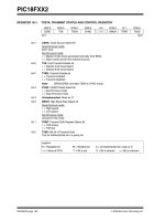
002 1008
X2
50 87
560
Ctrl. Panel
X2
60
23
20
22
20 = Enter Button
22 = UP Button
23 = Down Button
60 = Display
All dimensions in mm (1 mm = 0.03937 Inch)
1008
Legend
PT
Supply Voltage +
Supply Voltage 0 V
Supply Voltage (AC Voltage)
Switching Output
Switching Output
Contamination/Error Output
Contamination/Error Output
Input (analog or digital)
Teach Input
Time Delay (activation)
Shielding
Interface Receive Path
Interface Send Path
Ready
Ground
Clock
Output/Input programmable
(NO)
(NC)
(NO)
(NC)
Power over Ethernet
Safety Input
Safety Output
Signal Output
Ethernet Gigabit bidirect. data line (A-D)
Encoder 0-pulse 0-0 (TTL)
Platinum measuring resistor
not connected
Test Input
Test Input inverted
Trigger Input
Analog Output
Ground for the Analog Output
Block Discharge
Valve Output
Valve Control Output +
Valve Control Output 0 V
Synchronization
Receiver-Line
Emitter-Line
Grounding
Switching Distance Reduction
Ethernet Receive Path
Ethernet Send Path
Interfaces-Bus A(+)/B(–)
Emitted Light disengageable
Magnet activation
Input confirmation
Contactor Monitoring
Encoder A/A (TTL)
Encoder B/B (TTL)
Encoder A
Encoder B
Digital output MIN
Digital output MAX
Digital output OK
Synchronization In
Synchronization OUT
Brightness output
Maintenance
Wire Colors according to
DIN IEC 757
Black
Brown
Red
Orange
Yellow
Green
Blue
Violet
Grey
White
Pink
Green/Yellow
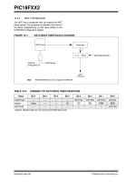
Table 1
Working Distance
Visual Field
20 mm
200 mm
1000 mm
16 × 12 mm
120 × 90 mm
600 × 450 mm
Specifications are subject to change without notice
002