5G RAN KPI reference(v100r015c10 01)(PDF) EN
Bạn đang xem bản rút gọn của tài liệu. Xem và tải ngay bản đầy đủ của tài liệu tại đây (1.1 MB, 43 trang )
5G RAN
V100R015C10
KPI Reference
Issue
01
Date
2019-06-06
HUAWEI TECHNOLOGIES CO., LTD.
Copyright © Huawei Technologies Co., Ltd. 2019. All rights reserved.
No part of this document may be reproduced or transmitted in any form or by any means without prior written
consent of Huawei Technologies Co., Ltd.
Trademarks and Permissions
and other Huawei trademarks are trademarks of Huawei Technologies Co., Ltd.
All other trademarks and trade names mentioned in this document are the property of their respective
holders.
Notice
The purchased products, services and features are stipulated by the contract made between Huawei and the
customer. All or part of the products, services and features described in this document may not be within the
purchase scope or the usage scope. Unless otherwise specified in the contract, all statements, information,
and recommendations in this document are provided "AS IS" without warranties, guarantees or
representations of any kind, either express or implied.
The information in this document is subject to change without notice. Every effort has been made in the
preparation of this document to ensure accuracy of the contents, but all statements, information, and
recommendations in this document do not constitute a warranty of any kind, express or implied.
Huawei Technologies Co., Ltd.
Address:
Huawei Industrial Base
Bantian, Longgang
Shenzhen 518129
People's Republic of China
Website:
Email:
Issue 01 (2019-06-06)
Copyright © Huawei Technologies Co., Ltd.
i
5G RAN
KPI Reference
Contents
Contents
1 5G RAN KPI Reference................................................................................................................ 1
1.1 Changes in 5G RAN KPI Reference.............................................................................................................................. 2
1.2 Accessibility KPIs.......................................................................................................................................................... 3
1.2.1 RRC Setup Success Rate (CU).................................................................................................................................... 3
1.2.2 RRC Setup Success Rate (Service) (CU).................................................................................................................... 5
1.2.3 RRC Setup Success Rate (Signaling) (CU)................................................................................................................. 6
1.2.4 NGSIG Connection Setup Success Rate (CU)............................................................................................................ 8
1.2.5 QoS Flow Setup Success Rate (CU)..........................................................................................................................10
1.2.6 Call Setup Success Rate (CU)................................................................................................................................... 13
1.3 Retainability KPIs.........................................................................................................................................................14
1.4 Mobility KPIs............................................................................................................................................................... 14
1.4.1 Intra-Frequency Handover Out Success Rate (CU)...................................................................................................14
1.4.2 Intra-RAT Handover In Success Rate (CU).............................................................................................................. 22
1.4.3 Inter-RAT Handover Out Success Rate (NR to LTE) (CU).......................................................................................26
1.5 Service Integrity KPIs.................................................................................................................................................. 28
1.5.1 User Downlink Average Throughput (DU)............................................................................................................... 28
1.5.2 User Uplink Average Throughput (DU).................................................................................................................... 28
1.5.3 Cell Downlink Average Throughput (DU)................................................................................................................ 29
1.5.4 Cell Uplink Average Throughput (DU).....................................................................................................................30
1.6 Utilization KPIs............................................................................................................................................................ 30
1.6.1 Downlink Resource Block Utilizing Rate (DU)........................................................................................................30
1.6.2 Uplink Resource Block Utilizing Rate (DU).............................................................................................................31
1.6.3 Average CPU Load.................................................................................................................................................... 31
1.7 Availability KPIs.......................................................................................................................................................... 32
1.7.1 Radio Network Unavailability Rate (CU)................................................................................................................. 32
1.8 Traffic KPIs.................................................................................................................................................................. 33
1.8.1 Downlink Traffic Volume (DU).................................................................................................................................33
1.8.2 Uplink Traffic Volume (DU)..................................................................................................................................... 33
1.8.3 Average User Number (CU)...................................................................................................................................... 34
1.8.4 Maximum User Number............................................................................................................................................ 35
1.9 NSA DC Accessibility and Mobility KPIs................................................................................................................... 35
1.9.1 SgNB Addition Success Rate.................................................................................................................................... 35
1.9.2 Intra-SgNB PSCell Change Success Rate................................................................................................................. 36
Issue 01 (2019-06-06)
Copyright © Huawei Technologies Co., Ltd.
ii
5G RAN
KPI Reference
Contents
1.9.3 Inter-SgNB PSCell Change Success Rate................................................................................................................. 37
1.9.4 SgNB-Triggered SgNB Abnormal Release Rate.......................................................................................................38
1.10 Reference Documents.................................................................................................................................................39
Issue 01 (2019-06-06)
Copyright © Huawei Technologies Co., Ltd.
iii
5G RAN
KPI Reference
1 5G RAN KPI Reference
1
5G RAN KPI Reference
Purpose
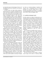
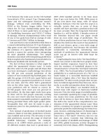
This document describes basic key performance indicators (KPIs) in the 5G RAN. The KPI
formulas are used in common scenarios. Only associated key counters are provided in this
document.
l The KPIs described in this document are for common scenarios, and the formulas are for instruction
only. For details on KPIs that are closely related to features, see the related feature parameter
description.
l This document lists only key counters associated with the KPIs. For details on other counters used
on the live network, see 3900 & 5900 Series Base Station Performance Counter Reference.
l If 3GPP protocols are updated, KPIs described in this document may change.
Intended Audience
This document is intended for:
l
Network planners
l
Network administrators
l
Network operators
Product Versions
The following table lists the product versions related to this document.
Product Name
Solution Version
Product Version
DBS5900
l SRAN15.1
V100R015C10
DBS5900 LampSite
l 5G RAN2.1
DBS3900
DBS3900 LampSite
BTS3900
Issue 01 (2019-06-06)
Copyright © Huawei Technologies Co., Ltd.
1
5G RAN
KPI Reference
1 5G RAN KPI Reference
Product Name
Solution Version
Product Version
BTS5900
BTS3900A
BTS5900A
BTS3900L
BTS5900L
BTS3900AL
BTS5900AL
Organization
1.1 Changes in 5G RAN KPI Reference
1.2 Accessibility KPIs
1.3 Retainability KPIs
1.4 Mobility KPIs
1.5 Service Integrity KPIs
1.6 Utilization KPIs
1.7 Availability KPIs
1.8 Traffic KPIs
1.9 NSA DC Accessibility and Mobility KPIs
1.10 Reference Documents
1.1 Changes in 5G RAN KPI Reference
This chapter describes the changes in 5G RAN KPI Reference.
01 (2019-06-06)
This is the first commercial release.
Compared with Draft A (2018-12-30), this issue includes the following new topics:
1.9 NSA DC Accessibility and Mobility KPIs
Compared with Draft A (2018-12-30), this issue does not include any changes or exclude any
topics.
Draft A (2018-12-30)
This is a draft.
Issue 01 (2019-06-06)
Copyright © Huawei Technologies Co., Ltd.
2
5G RAN
KPI Reference
1 5G RAN KPI Reference
Compared with V100R013C10, this issue includes the following changes:
l
Added KPIs in 1.2 Accessibility KPIs, 1.3 Retainability KPIs, 1.4 Mobility KPIs, and
1.7 Availability KPIs.
l
Update KPIs in 1.5.1 User Downlink Average Throughput (DU) and 1.5.2 User
Uplink Average Throughput (DU).
l
Revised KPI names to add CU or DU as suffix to KPI names.
1.2 Accessibility KPIs
Accessibility KPIs are used to measure the probability that a user successfully accesses the
network and requests services. The services include RRC connection setup, NGSIG setup,
PDU session setup, and QoS flow setup.
1.2.1 RRC Setup Success Rate (CU)
Description
According to 3GPP TS 38.331, the RRC connection setup procedure is triggered by different
causes. The upper layer determines the cause value for the RRC connection setup initiated by
the UE. The RRC connection setup for the cause value of mo-signaling is related to signaling.
The RRC connection setup for other reasons is related to services.
This KPI is calculated by the gNodeB when the UE initiates an RRC connection setup
procedure. As shown at point A in Figure 1-1, the total number of RRC connection setup
attempts due to different causes is incremented by 1 each time the gNodeB receives an
RRCSetupRequest message from the UE. As shown at point C, the total number of successful
RRC connection setups due to different setup causes is incremented by 1.
Issue 01 (2019-06-06)
Copyright © Huawei Technologies Co., Ltd.
3
5G RAN
KPI Reference
1 5G RAN KPI Reference
Figure 1-1 Measurement points for RRC connection setup
Definition
The RRC Setup Success Rate KPI is defined in Table 1-1.
Table 1-1 RRC Setup Success Rate (CU)
Issue 01 (2019-06-06)
Name
RRC Setup Success Rate (CU)
Object
Cell or radio network
Formul
a
RRCS_SR = (RRCSetupSuccess/RRCSetupAttempt) x 100%
Associa
ted
Counte
rs
RRC Setup Success Rate = (N.RRC.SetupReq.Succ/N.RRC.SetupReq.Att) x
100%
Unit
%
Note
None
Copyright © Huawei Technologies Co., Ltd.
4
5G RAN
KPI Reference
1 5G RAN KPI Reference
1.2.2 RRC Setup Success Rate (Service) (CU)
Description
According to 3GPP TS 38.331, the RRC connection setup procedure is triggered by different
causes. The upper layer determines the cause value for the RRC connection setup initiated by
the UE. The RRC connection setup for the cause value of mo-signaling is related to signaling.
The RRC connection setup for other reasons is related to services. This KPI is used to
evaluate the RRC connection setup success rate of services in a cell or on the entire network.
This KPI is calculated by the gNodeB when the UE initiates an RRC connection setup
procedure. As shown at point A in Figure 1-2, the total number of RRC connection setup
attempts due to services is incremented by 1 each time the gNodeB receives an
RRCSetupRequest message from the UE. As shown at point C, the number of successful RRC
connection setups due to services is incremented by 1.
Figure 1-2 Measurement points for RRC connection setup
Definition
The RRC Setup Success Rate (Service) KPI is defined in Table 1-2.
Table 1-2 RRC Setup Success Rate (Service) (CU)
Name
Issue 01 (2019-06-06)
RRC Setup Success Rate (Service) (CU)
Copyright © Huawei Technologies Co., Ltd.
5
5G RAN
KPI Reference
1 5G RAN KPI Reference
Object
Cell or radio network
Formul
a
RRCS_SRservice = (RRCSetupSuccessservice/RRCSetupAttemptservice) x 100%
Associat
ed
Counter
s
RRC Setup Success Rate (Service) = ((N.RRC.SetupReq.Succ.Emc +
N.RRC.SetupReq.Succ.HighPri + N.RRC.SetupReq.Succ.Mt +
N.RRC.SetupReq.Succ.MoData + N.RRC.SetupReq.Succ.MoVoiceCall +
N.RRC.SetupReq.Succ.MpsPri + N.RRC.SetupReq.Succ.MoSms +
N.RRC.SetupReq.Succ.MoVideoCall)/(N.RRC.SetupReq.Att.Emc +
N.RRC.SetupReq.Att.HighPri + N.RRC.SetupReq.Att.Mt +
N.RRC.SetupReq.Att.MoData + N.RRC.SetupReq.Att.MoVoiceCall +
N.RRC.SetupReq.Att.MpsPri + N.RRC.SetupReq.Att.MoSms +
N.RRC.SetupReq.Att.MoVideoCall)) x 100%
Unit
%
Note
None
1.2.3 RRC Setup Success Rate (Signaling) (CU)
Description
This KPI is used to evaluate the RRC connection setup success rate of signaling in a cell or on
the entire network. This KPI indicates the RRC setup success rate of the signaling-related
cause (mo-signaling).
This KPI is calculated by the gNodeB when the UE initiates an RRC connection setup
procedure. As shown at point A in Figure 1-3, the number of RRC connection setup attempts
due to signaling is incremented by 1 each time the gNodeB receives an RRCSetupRequest
message from the UE. As shown at point C, the number of successful RRC connection setups
due to signaling is incremented by 1.
Issue 01 (2019-06-06)
Copyright © Huawei Technologies Co., Ltd.
6
5G RAN
KPI Reference
1 5G RAN KPI Reference
Figure 1-3 Measurement points for RRC connection setup
Definition
The RRC Setup Success Rate (Signaling) KPI is defined in Table 1-3.
Table 1-3 RRC Setup Success Rate (Signaling) (CU)
Issue 01 (2019-06-06)
Name
RRC Setup Success Rate (signaling) (CU)
Object
Cell or radio network
Formul
a
RRCS_SRsignaling = (RRCSetupSuccesssignaling/RRCSetupAttemptsignaling) x
100%
Associat
ed
Counter
s
RRC Setup Success Rate (Signaling) = (N.RRC.SetupReq.Succ.MoSig/
N.RRC.SetupReq.Att.MoSig) x 100%
Unit
%
Note
None
Copyright © Huawei Technologies Co., Ltd.
7
5G RAN
KPI Reference
1 5G RAN KPI Reference
1.2.4 NGSIG Connection Setup Success Rate (CU)
Description
This KPI is used to evaluate the success rate of signaling connection setups over the NG
interface. This KPI includes counters such as the number of setup attempts of NG signaling
connections related to UEs and the number of successful setups of NG signaling connections
related to UEs.
The number of setup times of NG signaling connections related to UEs is incremented by 1
each time when the gNodeB sends an INITIAL UE MESSAGE to the AMF or receives the
first NG message from the AMF. INITIAL UE MESSAGE is the first NG message that the
gNodeB sends to the AMF. It contains the NAS configuration information related to UEs,
based on which the AMF sets up NG signaling connections for UEs. The first NG interface
message received from the AMF may be an INITIAL CONTEXT SETUP REQUEST,
DOWNLINK NAS TRANSPORT, or UE CONTEXT RELEASE COMMAND message. If
the message is received, an NG signaling connection is set up successfully.
As shown at point A in Figure 1-4, the number of NG signaling connection setup attempts is
incremented by 1 each time the gNodeB sends an INITIAL UE MESSAGE message to the
AMF.
As shown at point B in Figure 1-4, the number of successful NG signaling connection setups
is incremented by 1 each time the gNodeB sends an INITIAL UE MESSAGE message to the
AMF and receives the first NG message from the AMF.
Issue 01 (2019-06-06)
Copyright © Huawei Technologies Co., Ltd.
8
5G RAN
KPI Reference
1 5G RAN KPI Reference
Figure 1-4 Measurement points for signaling connection setup
Definition
The NGSIG Connection Setup Success Rate KPI is defined in Table 1-4.
Table 1-4 NGSIG Connection Setup Success Rate (CU)
Issue 01 (2019-06-06)
Name
NGSIG Connection Setup Success Rate (CU)
Object
Cell or radio network
Formul
a
NGSIGS_SR = (NGSIGConnectionEstablishSuccess/NGSIGConnectionEstablishAttempt) x 100%
Associat
ed
Counter
s
NGSIG Connection Setup Success Rate = (N.NGSig.ConnEst.Succ/
N.NGSig.ConnEst.Att) x 100%
Unit
%
Note
None
Copyright © Huawei Technologies Co., Ltd.
9
5G RAN
KPI Reference
1 5G RAN KPI Reference
1.2.5 QoS Flow Setup Success Rate (CU)
Description
This KPI is used to evaluate the QoS flow setup success rate of all services. The involved
counters include the number of QoS flow setup attempts and the number of successful QoS
flow setups.
1. As shown at point A in Figure 1-5, Figure 1-6, and Figure 1-7, the number of QoS flow
setup attempts is incremented by 1 each time the gNodeB receives an INITIAL CONTEXT
SETUP REQUEST, PDU SESSION RESOURCE SETUP REQUEST, or PDU SESSION
RESOURCE MODIFY REQUEST message from the AMF. If the INITIAL CONTEXT
SETUP REQUEST, PDU SESSION RESOURCE SETUP REQUEST, or PDU SESSION
RESOURCE MODIFY REQUEST message requests the setup of multiple QoS flows, the
number of QoS flow setup attempts is incremented by the number of QoS flow setups.
2. As shown in Figure 1-5 and Figure 1-6, the number of successful QoS flow setups is
incremented by 1 each time the gNodeB sends a PDU SESSION RESOURCE SETUP
RESPONSE, INITIAL CONTEXT SETUP RESPONSE, or PDU SESSION RESOURCE
MODIFY RESPONSE message to the AMF. If the PDU SESSION RESOURCE SETUP
RESPONSE, INITIAL CONTEXT SETUP RESPONSE, or PDU SESSION RESOURCE
MODIFY RESPONSE message contains multiple QoS flow setup success results, the total
number of successful QoS flow setups is accumulated based on the number in the message.
These counters are accumulated in the cell serving the UE.
Issue 01 (2019-06-06)
Copyright © Huawei Technologies Co., Ltd.
10
5G RAN
KPI Reference
1 5G RAN KPI Reference
Figure 1-5 Measurement points for initial context setup
Issue 01 (2019-06-06)
Copyright © Huawei Technologies Co., Ltd.
11
5G RAN
KPI Reference
1 5G RAN KPI Reference
Figure 1-6 Measurement points for PDU session setup
Figure 1-7 Measurement points for PDU session modification
Issue 01 (2019-06-06)
Copyright © Huawei Technologies Co., Ltd.
12
5G RAN
KPI Reference
1 5G RAN KPI Reference
Definition
Table 1-5 lists the definition of the QoS flow setup success rate of all services. For details
about how to measure the number of QoS flow setup attempts and the number of successful
setups, see "Description" in this section.
Table 1-5 Qos Flow Setup Success Rate (CU)
Name
Qos Flow Setup Success Rate (CU)
Object
Cell or radio network
Formul
a
Qos FlowS_SR = (QosFlowSetupSuccess/QosFlowSetupAttempt) x 100%
Associat
ed
Counter
s
QoS Flow Setup Success Rate = (N.QosFlow.Est.Succ/N.QosFlow.Est.Att) ×
100%
Unit
%
Note
None
1.2.6 Call Setup Success Rate (CU)
Description
This KPI is used to evaluate the call setup success rate of all services, including the RRC
connection setup success rate for services, NG signaling connection setup success rate, and
QoS flow setup success rate.
Definition
The Call Setup Success Rate KPI is defined in Table 1-6. This KPI is the product of the RRC
connection setup success rate for services, NG signaling connection setup success rate, and
QoS flow setup success rate.
Table 1-6 Call Setup Success Rate
Issue 01 (2019-06-06)
Name
Call Setup Success Rate (CU)
Object
Cell / Radio Network (CU)
Formul
a
CSSR = (RRCSetupSuccessservice/RRCSetupAttemptservice) x
(NGSIGConnectionEstablishSuccess/NGSIGConnectionEstablishAttempt) x
(QosFlowSetupSuccess/QosFlowSetupAttempt) x 100%
Copyright © Huawei Technologies Co., Ltd.
13
5G RAN
KPI Reference
1 5G RAN KPI Reference
Associat
ed
Counter
s
Call Setup Success Rate = ((N.RRC.SetupReq.Succ.Emc +
N.RRC.SetupReq.Succ.HighPri + N.RRC.SetupReq.Succ.Mt +
N.RRC.SetupReq.Succ.MoData + N.RRC.SetupReq.Succ.MoVoiceCall +
N.RRC.SetupReq.Succ.MpsPri + N.RRC.SetupReq.Succ.MoSms +
N.RRC.SetupReq.Succ.MoVideoCall)/(N.RRC.SetupReq.Att.Emc +
N.RRC.SetupReq.Att.HighPri + N.RRC.SetupReq.Att.Mt +
N.RRC.SetupReq.Att.MoData + N.RRC.SetupReq.Att.MoVoiceCall +
N.RRC.SetupReq.Att.MpsPri + N.RRC.SetupReq.Att.MoSms +
N.RRC.SetupReq.Att.MoVideoCall)) x (N.NGSig.ConnEst.Succ/
N.NGSig.ConnEst.Att) x (N.QosFlow.Est.Succ/N.QosFlow.Est.Att) x 100%
Unit
%
Note
None
1.3 Retainability KPIs
Retainability KPIs are used to evaluate network's capability to retain services of UEs in
connected mode on the network and indicate whether the system can maintain the service
quality at a certain level.
Retainability KPIs, such as the service drop rate, are not defined because protocols are not specified. The
definition of 5G retainability KPIs will be provided after the standards are specified in protocols.
1.4 Mobility KPIs
Mobility KPIs are used to evaluate the mobility performance of the NR network, which is
critical to user experience. Three categories of mobility KPIs are defined based on the
following handover types: intra-RAT intra-frequency, intra-RAT inter-frequency, and interRAT.
1.4.1 Intra-Frequency Handover Out Success Rate (CU)
Description
This KPI indicates the success rate of intra-NR intra-frequency outgoing handovers. The
intra-frequency outgoing handovers are classified into intra- and inter-gNodeB outgoing
handovers.
Intra-gNodeB Outgoing Handover
Intra-gNodeB outgoing handovers can be further classified into handovers with RRC
connection reestablishment and handovers without RRC connection reestablishment.
l
Intra-gNodeB outgoing handovers without RRC connection reestablishment
As shown in Figure 1-8, the source cell and the target cell operate at the same frequency.
At point B, when the gNodeB sends an RRC Reconfiguration message carrying the
handover command to the UE, the gNodeB counts the number of intra-gNodeB intrafrequency outgoing handover execution attempts in the source cell. At point C, when the
Issue 01 (2019-06-06)
Copyright © Huawei Technologies Co., Ltd.
14
5G RAN
KPI Reference
1 5G RAN KPI Reference
gNodeB receives an RRC Reconfiguration Complete message from the UE, which
indicates that the handover is complete, the gNodeB counts the number of successful
intra-gNodeB intra-frequency outgoing handover executions in the source cell.
Figure 1-8 Intra-gNodeB outgoing handovers without RRC connection reestablishment
l
Intra-gNodeB outgoing handovers with RRC connection reestablishment
As shown in Figure 1-9, the source cell and the target cell operate at the same frequency.
At point B, when the gNodeB sends an RRC Reconfiguration message carrying the
handover command to the UE, the gNodeB counts the number of intra-gNodeB intrafrequency outgoing handover execution attempts in the source cell. At point C, when the
gNodeB receives an RRC Reestablishment Complete message from the UE, the gNodeB
counts the number of successful intra-gNodeB intra-frequency outgoing handover
executions in the source cell.
Issue 01 (2019-06-06)
Copyright © Huawei Technologies Co., Ltd.
15
5G RAN
KPI Reference
1 5G RAN KPI Reference
Figure 1-9 Intra-gNodeB outgoing handovers with RRC connection reestablishment
Inter-gNodeB Outgoing Handover
Inter-gNodeB outgoing handovers can be further classified into handover without RRC
connection reestablishment, handover with RRC connection reestablishment to the target
cell, and handover with RRC connection reestablishment to the source cell.
l
Inter-gNodeB outgoing handover without RRC connection reestablishment
As shown in Figure 1-10 and Figure 1-11, the source cell and target cell operate at the
same frequency. When the source gNodeB sends an RRC Reconfiguration message
containing the handover command to the UE, the source gNodeB counts the number of
intra-frequency outgoing handover execution attempts in the source cell at point B.
When the source gNodeB receives a UE CONTEXT RELEASE message from the target
gNodeB or receives a UE CONTEXT RELEASE COMMAND message from the AMF,
indicating that the UE successfully accesses the target cell, the source gNodeB counts the
number of successful intra-frequency outgoing handover executions in the source cell at
point C.
Issue 01 (2019-06-06)
Copyright © Huawei Technologies Co., Ltd.
16
5G RAN
KPI Reference
1 5G RAN KPI Reference
Figure 1-10 Xn-based inter-gNodeB outgoing handover without RRC connection
reestablishment
Figure 1-11 NG-based inter-gNodeB outgoing handover without RRC connection
reestablishment
l
Issue 01 (2019-06-06)
Inter-gNodeB outgoing handover with RRC connection reestablishment to the target cell
Copyright © Huawei Technologies Co., Ltd.
17
5G RAN
KPI Reference
1 5G RAN KPI Reference
As shown in Figure 1-12 and Figure 1-13, the source cell and target cell operate at the
same frequency. When the source gNodeB sends an RRC Reconfiguration message
containing the handover command to the UE, the source gNodeB counts the number of
intra-frequency outgoing handover execution attempts in the source cell at point B.
When the source gNodeB receives a UE CONTEXT RELEASE message from the target
gNodeB or receives a UE CONTEXT RELEASE COMMAND message from the AMF,
indicating that the UE successfully accesses the target cell, the source gNodeB counts the
number of successful intra-frequency outgoing handover executions in the source cell at
point C.
Figure 1-12 Xn-based inter-gNodeB outgoing handover with RRC connection
reestablishment to the target cell
Issue 01 (2019-06-06)
Copyright © Huawei Technologies Co., Ltd.
18
5G RAN
KPI Reference
1 5G RAN KPI Reference
Figure 1-13 NG-based inter-gNodeB outgoing handover with RRC connection
reestablishment to the target cell
l
Inter-gNodeB outgoing handover with RRC connection reestablishment to the source
cell
As shown in Figure 1-14 and Figure 1-15, the source cell and target cell operate at the
same frequency. At point B, when the source gNodeB sends an RRC Reconfiguration
message carrying the handover command to the UE, the source gNodeB counts the
number of intra-frequency outgoing handover execution attempts in the source cell. At
point C, when the source gNodeB receives an RRC Reestablishment Complete message
from the UE, the source gNodeB counts the number of successful intra-frequency
outgoing handover executions in the source cell.
Issue 01 (2019-06-06)
Copyright © Huawei Technologies Co., Ltd.
19
5G RAN
KPI Reference
1 5G RAN KPI Reference
Figure 1-14 Xn-based inter-gNodeB outgoing handover with RRC connection
reestablishment to the source cell
Issue 01 (2019-06-06)
Copyright © Huawei Technologies Co., Ltd.
20
5G RAN
KPI Reference
1 5G RAN KPI Reference
Figure 1-15 NG-based inter-gNodeB outgoing handover with RRC connection
reestablishment to the source cell
Definition
The Intra-Frequency Handover Out Success Rate KPI is defined in Table 1-7. The number of
outgoing handover execution attempts and the number of successful outgoing handover
executions are collected based on the description in "Description" in this section.
Table 1-7 Intra-frequency Handover Out Success Rate (CU)
Issue 01 (2019-06-06)
Name
Intra-frequency Handover Out Success Rate (CU)
Object
Cell or radio network
Formul
a
IntraFreqHOOut_SR = (IntraFreqHOOutSuccess/IntraFreqHOOutAttempt) x
100%
Associat
ed
Counter
s
Intra-Frequency Handover Out Success Rate =
((N.HO.IntraFreq.Ng.IntergNB.ExecSuccOut +
N.HO.IntraFreq.Xn.IntergNB.ExecSuccOut +
N.HO.IntraFreq.IntragNB.ExecSuccOut)/
(N.HO.IntraFreq.Ng.IntergNB.ExecAttOut +
N.HO.IntraFreq.IntragNB.ExecAttOut +
N.HO.IntraFreq.Xn.IntergNB.ExecAttOut)) x 100%
Unit
%
Copyright © Huawei Technologies Co., Ltd.
21