Thiết kế và lập trình hệ thống - Chương13
Bạn đang xem bản rút gọn của tài liệu. Xem và tải ngay bản đầy đủ của tài liệu tại đây (2.25 MB, 13 trang )
Systems Design and Programming Basic I/O I CMPE 310
1 (April 1, 2002)
UMBC
U M B C
U
N
I
V
E
R
S
I
T
Y
O
F
M
A
R
Y
L
A
N
D
B
A
L
T
I
M
O
R
E
C
O
U
N
T
Y
1
9
6
6
Basic I/O Instructions
We discussed IN, OUT, INS and OUTS as instructions for the transfer of data
to and from an I/O device.
IN and OUT transfer data between an I/O device and the microprocessor’s
accumulator (AL, AX or EAX).
The I/O address is stored in:
• Register DX as a 16-bit I/O address (variable addressing).
• The byte, p8, immediately following the opcode (fixed address).
Only 16-bits (A
0
to A
15
) are decoded.
Address connections above A
15
are undefined for I/O instructions.
0000H-03XXH are used for the ISA bus.
INS and OUTS transfer to I/O devices using ES:DI and DS:SI, respectively.
IN AL, 19H
;8-bits are saved to AL from I/O port 19H.
IN EAX, DX
;32-bits are saved to EAX.
OUT DX, EAX
;32-bits are written to port DX from EAX.
OUT 19H, AX
;16-bits are written to I/O port 0019H.
Systems Design and Programming Basic I/O I CMPE 310
2 (April 1, 2002)
UMBC
U M B C
U
N
I
V
E
R
S
I
T
Y
O
F
M
A
R
Y
L
A
N
D
B
A
L
T
I
M
O
R
E
C
O
U
N
T
Y
1
9
6
6
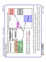
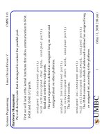
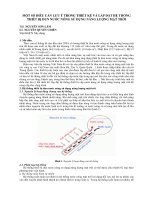
Isolated versus Memory-Mapped I/O
Isolated and Memory-Mapped I/O:
In the Isolated scheme, IN, OUT, INS and OUTS are required.
In the Memory-mapped scheme, any instruction that references memory
can be used.
8-bit port addresses used to access system board device, e.g. timer and key-
board.
16-bit port addresses used to access serial and parallel ports, harddrives, etc.
00000
FFFFF
Memory
1M X 8
0000
FFFF
64K X 8
I/O
I/O
64K X 8
Separate spaces
Overlapped
Hardware using M/IO and
W/
R needed to develop
signals
IORC and IOWC.
Requires IN, OUT, INS and
OUTS
IORC and IOWC not required.
Any data transfer instruction.
A portion of the memory space
is used for I/O devices.
spaces
Disadvantage:
Advantage:
Disadvantage:
Systems Design and Programming Basic I/O I CMPE 310
3 (April 1, 2002)
UMBC
U M B C
U
N
I
V
E
R
S
I
T
Y
O
F
M
A
R
Y
L
A
N
D
B
A
L
T
I
M
O
R
E
C
O
U
N
T
Y
1
9
6
6
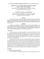
I/O Map
0000
I/O Expansion Area
DMA controller
Interrupt controller
Timer
8255(PPI)
COM 2
Hard disk
LPT 1
CGI adapter
Floppy disk
COM 1
FFFF
0010
0020
0040
0024
0060
0044
02F8
0064
0320
0300
0378
0330
03D0
0380
03F0
03E0
03F8
Fixed I/O areas
0400
Fixed Port
I/O instuctions
Variable Port
I/O instuctions
Computer system
and ISA Bus
PCI Bus, user apps
and main-board
functions
Systems Design and Programming Basic I/O I CMPE 310
4 (April 1, 2002)
UMBC
U M B C
U
N
I
V
E
R
S
I
T
Y
O
F
M
A
R
Y
L
A
N
D
B
A
L
T
I
M
O
R
E
C
O
U
N
T
Y
1
9
6
6
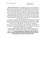
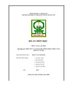
Basic I/O Interface
The basic input device (to the microprocessor) is a set of tri-state buffers.
The basic output device (from the microprocessor) is a set of latches.
Basic Input Interface:
VCC
Data Bus
SEL
1A
1
1A
2
1A
3
1A
4
2A
1
2A
2
2A
3
2A
4
1Y
1
1Y
2
1Y
3
1Y
4
2Y
1
2Y
2
2Y
3
2Y
4
1G
2G
74ALS244
10KΩ
When tri-states are enabled,
Toggle switches
are data source.
8-bit input port
microprocessor can read
state of toggle switches into
AL (using IN instruction).
I/O port address decoded to SEL
Systems Design and Programming Basic I/O I CMPE 310
5 (April 1, 2002)
UMBC
U M B C
U
N
I
V
E
R
S
I
T
Y
O
F
M
A
R
Y
L
A
N
D
B
A
L
T
I
M
O
R
E
C
O
U
N
T
Y
1
9
6
6
Basic I/O Interface
Basic Output Interface:
In this case, the data from the OUT instruction is latched using
SEL.
SEL
Data Bus
VCC
330Ω
D
0
D
1
D
2
D
3
D
4
D
5
D
6
D
7
Q
0
Q
1
Q
2
Q
3
Q
4
Q
5
Q
6
Q
7
OC
CLK
U1
D flip-flops hold
Light-emitting
diodes emit
74ALS374
data from microprocessor
when Q output
is set to logic 0.