Tài liệu Điện thoại di động mạng lưới Radio P11 pdf
Bạn đang xem bản rút gọn của tài liệu. Xem và tải ngay bản đầy đủ của tài liệu tại đây (361.74 KB, 26 trang )
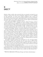
11
Personal Handyphone System
(PHS)
∗
11.1 Development of the Personal Handyphone
System in Japan
At the end of the 1980s, two cordless telephone systems, CT2 and DECT, had
entered the second step of their development process. At that time, Japan had
not yet developed any comparable technology; therefore work began in 1989
on a Japanese cordless standard, which has become known as the Personal
Handyphone System (PHS). Disadvantages of conventional cellular telephone
systems, such as high costs of infrastructure and cell-planning resulting in
high communication fees, had motivated the development of a less expensive
system.
The review by the Telecommunications Technology Council, a consult-
ing organization for the Japanese Ministry of Posts and Telecommunications
(MPT), and the technical study by the Research and Development Centre
for Radio Systems (RCR) of PHS started at the beginning of 1991 in Japan.
The PHS air interface was then standardized through the publication of the
RCR STD-28 [1], Version 1, in December 1993. Various field trials in the
Sapporo area in October 1993, and in the Tokyo area in April 1994, were then
conducted to prove the feasibility of PHS for various demands and services,
respectively.
The PHS service was commercially launched in Japan by three opera-
tor groups—(NTT (Nippon Telegraph and Telephone) Personal Group, DDI
(Daini Denden Inc.) Pocket Telephone Group and the Astel Group)—in July
1995. The technology gained unprecedent popularity, with the number of
subscribers reaching the six million mark by the beginning of 1997—just two
years after its introduction. As of August 1998, the number of subscribers was
about 6.4 million [4]. Attracted by the success in Japan, other Asian coun-
tries, including Thailand and Hong Kong, and some South American countries
announced plans to establish PHS networks.
∗
With the collaboration of Matthias Siebert
Mobile Radio Networks: Networking and Protocols. Bernhard H. Walke
Copyright © 1999 John Wiley & Sons Ltd
ISBNs: 0-471-97595-8 (Hardback); 0-470-84193-1 (Electronic)
592 11 Personal Handyphone System (PHS)
Table 11.1: Parameters of the Personal Handyphone System
Frequency band 1893.5–1919.6 MHz
Access method TDMA/TDD
Channel assign. method DCA (with restrictions for control channels)
Number of RF carriers 87 (incl. 6 control and 4 guard channels)
Carrier spacing 300 kHz
Frame duration 5 ms
Number of slots/frame 8
Modulation π/4 DQPSK
Output power (average) CS: 500 mW or less
PS: 10 mW or less
Traffic channels/transceiver 3 (resp. 4)
Transmission rate/carrier 384 kbit/s
Net bit rate/channel 32 kbit/s user data
6.8 or 12.4 kbit/s signalling information
11.2 System Overview
The aims of PHS span those of cordless and cellular systems, encompassing the
idea of a low-cost wireless handset that can be used in both indoor and out-
door environments to access fixed network supported services. Like cordless
systems (see Chapter 8), PHS provides access to private communication sys-
tems for greater flexibility in the office environment or at home. It also forms
the basis for public network access by subscribers moving with pedestrian
speed. A microcellular structure has been adopted; thus the radio transmit
power can be much smaller than that of existing cellular telephone systems.
As described for DECT, by means of dynamic channel allocation (DCA),
cell station engineering is simplified and a multi-operator environment in the
same service area is facilitated. However, some restrictions concerning the
fixed control frequencies still require a certain amount of frequency planning
in advance.
Various services are supported. Apart from telephone services, the PHS
air interface supports voiceband data and facsimile communications at rates
up to 9.6 kbit/s. Also, there is the capability of data transmission at rates of
32/64 kbit/s. According to [5] the upper limit of data transmission has been
raised to 128 kbit/s, using four channels simultaneously. An overview of the
parameters of the Personal Handyphone System is given in Table 11.1.
Like CT2 (see Section 8.1), PHS defines only two network elements: termi-
nal and base station. The nomenclature for a base station is cell station (CS)
and a PHS terminal is referred to as a personal station(PS).
11.3 PHS Radio Characteristics 593
11.2.1 Personal Station (PS)
Similarly to DECT (see Chapter 9), personal stations transmit with an aver-
age (peak) RF power of 10 mW (80 mW). As a special feature, comparable
to the TETRA system (see Section 6.3), PHS also specifies direct radio com-
munication between a pair of terminals. The direct mode of communication
does not need the intervention of cell stations (CSs). As shown in Figure 11.4,
ten frequency carriers are designated for such a use. However, since it is only
a supplementary service that should not restrict the ordinary use of these
frequencies, the direct communication must end within a time limit of three
minutes.
As PHS is a system for private and public use, PSs support two modes of
operation, namely public and private operation modes. The public operation
mode enables the PS to access the public PHS service areas. The private
operation mode enables a PS to access private systems like a wireless PBX
or the home digital cordless system. The same PS can be used at home and
in the office by selecting a relevant private mode within the pre-registered
private systems.
Terminal mobility allows the PS a smooth transition between public and
private PHS services by selecting the appropriate mode on the PS. This se-
lection can also be done automatically (Automatic Selection Mode). When
the PS is within the range of both services, it will operate in a predetermined
mode. Optionally, an automatic dual-mode operation is possible, where the
PS can be paged from both the public system and the private system when it
is within the range of both.
11.2.2 Cell Station (CS)
A cell station consists of CS equipment and antennas. These two parts to-
gether create a microcell service area with a radius of several hundred metres.
Cell stations control most of the tasks concerning the air interface. These in-
clude dynamic channel allocation (DCA), superframe establishment, diversity
support, and many more. What is unique is the use of diversity, both for the
uplink (by means of post-detection selection) and for the downlink (by means
of transmitter antenna selection), controlled by the CS. The average (peak)
RF power depends on the kind of CS. An outdoor standard-power CS, for
example, transmits at an RF power of 20 mW (160 mW).
11.3 PHS Radio Characteristics
11.3.1 Speech Coding
Similarly to DECT, a 64 kbit/s full-rate voice coding is employed first; then
the signal is transcoded into 32 kbit/s ADPCM (Adaptive Differential Pulse
Code Modulation) based on the ITU-T Recommendation G.726.
594 11 Personal Handyphone System (PHS)
Half-rate and quarter-rate voice coding methods are not specified at
present, but a superframe configuration allows multiple codecs with lower
rates, down to 8 kbit/s, to be incorporated in the system when they become
available.
The ADPCM compresses speech data without degrading speech quality.
Performance of voiceband data transmission via modems is not significantly
degraded, and non-speech service can be supported.
11.3.2 Modulation
PHS employs a π/4-shifted DQPSK modulation with a roll-off factor of 0.5.
This modulation scheme permits a variety of demodulation techniques to be
used, such as delay detection, coherent detection and frequency discrimination
detection. Furthermore, the use of the DQPSK modulation method enables
a higher spectrum utilization efficiency compared with GMSK modulation.
11.3.3 Access Method
In common with DECT, the access method applied in PHS is hybrid
time-division/frequency-division multiple-access (TDMA/FDMA) with time-
division duplexing (TDD). The use of TDD also makes it possible to modify
service bit rates. The latest ARIB Standard, RCR STD-28 Version 3, issued
in November 1997, lists the specifications for PHS 64 kbit/s digital data trans-
mission. It enables high-speed wireless access to the ISDN network from the
PS by assigning a second TCH in parallel.
A TDMA frame has a length of 5 ms and carries 8 slots. The first four
slots are downlink; the other four slots are uplink slots (see Table 11.1 and
Figure 11.1).
The TDMA/TDD technology allows deviation from the allocation of paired
transmit/receive channels, which is usually required in order to accomplish
symmetric two-way communication and is able to support asymmetric com-
munication relationships. TDMA/TDD is flexible, because it does not need
paired bands and both the lower and upper ends of the spectrum can easily
be expanded to accommodate needs as in RCR STD-28 Version 3.
11.3.3.1 Communication Physical Slot Designation Method
Designation of communication physical slots is performed by a signal (link
channel assignment message) on a Signalling Control Channel (SCCH) (see
Section 11.4.1.3), sent from CS. The slot designation position is indicated by
the slot number, counted relatively to the first slot starting 2.5 ms after the
signal (link channel assignment message) has been received by the PS.
An example is given in Figure 11.1: here the link channel assignment mes-
sage is transmitted in the first TDMA slot. The PS waits 2.5 ms after the
reception, and then starts to count the following slots until the relative value
maps with that given in the message. As a bidirectional channel is always
11.3 PHS Radio Characteristics 595
87654321
8765432187654321 87654321
161514131211109
87654321 161514131211109 Relative slot number from
personal station’s point of view
uplink reception
Slots for downlink/
Link channel
assignment message
(first slot)
The slot designation for the CS corresponding
to the PS’s slot position is shifted half a frame
Absolute TDMA slot number
Relative slot number from
cell station’s point of view
Slots for downlink/
uplink transmission
2.5 ms
Figure 11.1: Example of relative slot numbers
made up of a pair of slots, the second slot is defined to follow half a frame
length (2.5 ms) later, corresponding to the TDD scheme.
Thus the physical time slot number is specified by a combination of abso-
lute and relative slot number by the CS. The TDMA slot number (SN) of a
communication carrier is obtained from the following equation:
TDMA SN = {(absolute SN + relative SN − 2)mod4} + 1 (11.1)
11.3.3.2 PHS Superframe Structure
The minimum cycle of the downlink logical control channel (LCCH) that
specifies the slot position of the first repeated LCCH elements is specified as
the LCCH superframe. All transmission/reception timing of physical slots
for controlling intermittent transmission and SCCH uplink slot designation is
generated based on the superframe structure.
Elements (subchannels) of the downlink LCCH (see Section 11.4.1 for a de-
tailed description) are the Broadcast Control Channel (BCCH), Paging Chan-
nels (PCH, P
1
− P
k
: number of paging groups = k), the Signalling Control
Channel (SCCH) and an optional User-Specific Control Channel (USCCH).
The BCCH must be transmitted in the first slot of the LCCH superframe
whereby the lead position of the superframe is reported. In detail, this is
done by means of profile data contained in the radio channel information
broadcasting message (see Section 11.5.5.1). If necessary, it is possible to
temporarily steal LCCH elements, except for BCCH, and send some other
LCCH elements.
The downlink logical control channel (LCCH) has the superframe structure
shown in Figure 11.2. After each n TDMA frames, the CS intermittently
transmits an LCCH slot (as discussed in Section 11.4.1, the CS does not
transmit control signals in each TDMA frame). The parameter m defines
the number of LCCH elements that have to be transmitted until all kinds of
information have been conveyed once.
596 11 Personal Handyphone System (PHS)
187 2 81 65 332 54
1
2
1
4
2 3
4
1
1
3
3 1 2
5 ms TDMA frame
2
65
Slots used by CS
Downlink Uplink
LCCH superframe
ms downlink intermittent transmission cyclen
ms
Downlink logical control
channel (LCCH)
m
Uplink logical control
channel (LCCH)
n
nm
5
5
Figure 11.2: PHS superframe
240 bit, 625
PR
R CRC
4
Guard
1616
32
µs
(b) Control physical slot
(a) Communication physical slot (traffic slot)
SS
2
R
4
CI
4
CRC
16
Guard
16
SS
2
Unique
16
4
CI SACCH
16
Information
160
Word
Word
Unique
42 or 70
Header
62 or 34
6
PR
Information
62
Figure 11.3: PHS time-slot formats
For the uplink, no superframe structure is defined. Personal stations trans-
mit their first signalling message by using the Slotted Aloha protocol (see
Section 2.8.1), using an uplink SCCH slot, if they want a connection to be
established.
11.3.4 Slot Structure
As a frame in PHS lasts 5 ms and each frame consists of 8 slots, each slot has
a length of 625 ➭s in which 240 bits can be arranged. PHS specifies several
time-slot formats corresponding to different logical channels. Basically, there
are two categories: control physical slots used by common control channels
(CCHs), and communication physical slots used by traffic channels (TCHs);
see Figure 11.3.
In contrast to the DECT standard, where, as a concession to more cost-
effective hardware, certain slots (and related traffic channels) might not be
used (see Figure 9.50), PHS makes use of all its time slots. Therefore all
slot formats start with a 4-bit ramp time in which the PS or CS turns on
its transmitter and a 2-bit start symbol for establishing the phase of the re-
mote demodulator. At the end of each slot format, there is another common
data field for performing an ITU-T 16-bit CRC. The start symbol is followed
11.3 PHS Radio Characteristics 597
by a preamble, a layer-1 signal pattern used to establish bit synchronization.
Its number of bits depends on the kind of slot format. Together, start sym-
bol and preamble are repetitions of the pattern 1001. With control physical
slots, a preamble of 62 bits is used to allow synchronization for each slot in-
dependently; with communication physical slots, a preamble of 6 bits serves
to update the synchronization established in the previously transmitted slots.
Additionally, all time slots carry a unique word, known in advance by the
receiver, which is different for the downlink and uplink channels. It also differs
for control physical slots and communication physical slots, so that it helps to
distinguish between them. Moreover, together with the CRC check, it is used
for error detection. As it is known in advance, the receiving party listening
for its dedicated slot either detects it or not (unique word detection error).
The channel identifier follows right after the unique word. It is similar
to the flag bits in GSM bursts. For example, the channel identifier sequence
0000 indicates that the time slot carries user information (TCH), while 0001
indicates that the time slot carries a fast associated control channel (FACCH).
Slow associated control channels (SACCH) do not have a special channel
identifier since they are part of each communication physical slot, with the
exception of an optional user-specific packet channel (USPCH), described in
Section 11.4.2.4.
The most important data field in Figure 11.3 (a) is the information field,
which carries the user data. For telephone services such as voice transmission
it consists of 160 bits from an adaptive differential pulse code modulation
(ADPCM) encoder. Therefore, in common with DECT, the bit rate carried
by communication physical slots (with the exception of USPCH) is
160 bit/frame
0.005 s/frame
= 32 kbit/s (11.2)
Control physical slots have headers containing addresses. Broadcasting
point-to-multipoint channels such as the broadcasting control channel (BCCH)
and the paging channel (PCH) only need to transmit a 42-bit CS identification
code. Thus the information field contains 62 bits. On the other hand, bidirec-
tional point-to-point channels such as the signalling control channel (SCCH)
need to specify a CS identification code (42 bits) and a PS identification code
(28 bits). In these channels the length of the information field is 34 bit. This
implies that the information rate for logical control channels is either
62 bit/frame
0.005 s/frame
= 12.4 kbit/s or
34 bit/frame
0.005 s/frame
= 6.8 kbit/s (11.3)
Finally, all slot formats have a guard time of 41.7 ➭s, corresponding to
16 bits, i.e., a burst carried in a slot is 224 bits in length.
598 11 Personal Handyphone System (PHS)
11.3.5 Radio-Frequency Band
The PHS band spans 26.1 MHz from 1893.5–1919.6 MHz. Originally the radio-
frequency band allocated for PHS service spanned 23.1 MHz in the range of
1.895–1918.1 MHz. Because it was working close to capacity in hot-spot areas,
an extension became necessary. There are 87 carriers in the PHS band, with
a spacing of 300 kHz. Figure 11.4 shows the relationship between the PHS
frequency band and the carrier numbers. Control carriers for private use are
assigned to 1898.450 MHz and 1900.250 MHz for Japan, and 1903.850 MHz
and 1905.650 MHz for other countries. In Japan, four control carriers are
reserved for public use. One control channel is assigned to each of the three
PHS operators, and the remaining one is set aside as a spare channel. In order
to protect the public control channels from adjacent channel interferences,
they are enclosed by guard channels. Currently the spectrum for public use
is 15 MHz. The spectrum for private use is 11.1 MHz, which can be shared
with public use. In addition, the first 10 carriers of private use (1895.15–
1897.85 MHz) are also designated for direct communication between personal
stations (Transceiver mode, Walkie Talkie).
11.3.6 Frequency Allocation
As Figure 11.4 shows, the PHS frequency band is not separately allocated
for each operator, but is shared, with the exception of the channels that are
pre-assigned as control channels dynamically by all PHS operators by means
of dynamic channel assignment (DCA). This is an autonomous decentralized
radio channel control technology, which enables efficient and flexible use of
frequencies and time slots according to the local interference levels of CS and
PS.
In contrast to the DECT system, where it is the mobile’s task to select
a suitable channel, in PHS this is done by the cell station. With a link
channel establishment request or a TCH switching channel request (see Sec-
tion 11.5.5.1), the PS asks for the assignment of a channel. The cell station can
automatically pick up carriers at random and select an available carrier that
has no interference problem. As a result of checking signal strength when a
call is established, the CS renews an internal two-dimensional frequency–time
matrix with available channels.
If no carrier is available, the CS refuses the request. The PS will then
automatically request again. This can be done up to three times; then the PS
has to wait a certain time before another try is possible.
11.3.7 Microcellular Architecture
PHS applies a microcellular architecture, which permits efficient spectrum
utilization and the use of low-power handsets. Thus long standby/talk times
can be realized. In cooperation with PHS, large numbers of cell stations can
be deployed without planning. (In fact, this is only true for traffic channels.
11.3 PHS Radio Characteristics 599
18
(Japan)
(Private Use) *2
50
60
40
38
69
70
71
72
73
74
75
76
77
78
79
80
81
Control Channel
Direct
Public Use
(Private Use) *2
(Japan)
82
Carrier
number
Communication
between
PSs
(Private Use)
Control Channel
251
252
255
1893.650
.950
1
5
10
12
30
36
1905,950
1900,250
1898,450
Control Channel 1
Control Channel 2
Control Channel 3
Spare Control-ch.
Public Use
1897,850
1896.350
1894.850
1905.650
37
20 1900.850
1903.850
1919.450
1917.950
1917.350
1916.750
1916.150
1915.850
1915.550
1912.850
1909.850
1906.850
1906.250
Public Use
*2 Used for communication carrier, outside Japan
*1 Frequency band for private use (public use possible)
87 frequencies
Frequency spacing 300 kHz
Private Use *1
(Private Use) *3
(Outside Japan)
Control Channel
frequency
Carrier
[MHz]
number
Carrier
Carrier
[MHz]
frequency
*3 Used for communication carrier within Japan
Figure 11.4: PHS frequency table
Concerning the fixed control channels, frequency planning still has to be done).
For example, NTT launched a PHS service in July 1995 with some 25 000
standard cell stations in Tokyo, using a conventional small-cell structure, 150–
200 m, with antennas mounted on public telephone boxes.
The microcellular technology allows easy addition and removal of CSs in
the field, based on factors such as traffic demand and the presence of other
operators serving the same area. Cell stations with 10 mW of average power
are deployed at about 200 m spacing in downtown areas. Wider separation
between cell stations is possible using CSs with higher-power transmitters and
extremely low-noise amplifiers.
600 11 Personal Handyphone System (PHS)
11.3.8 Handover
In PHS, a handover is called channel switching. During a call, both network
elements—the cell station and the personal station—observe the channel qual-
ity. This is done by evaluating the radio signal strength indicator (RSSI) and
the frame-error ratio. The latter is indicated by detected errors in the cyclic
redundancy check (CRC) in every time slot, and also unique word errors if
there is a call in progress. In response to deteriorating quality, either network
element can initiate a handover.
PHS distinguishes between two types of handover: one is called recalling-
type and the other traffic channel switching-type.
TCH switching-type If a high frame-error ratio is detected but the received
signal strength indicates that the terminal is still in the vicinity of the
serving cell station, this is mostly due to rising interference. Remedial
measures can be taken by switching to another slot or frequency; thus
the serving cell station does not have to be changed. To do so, the
terminal transmits a TCH switching request message on the fast associ-
ated control channel (FACCH). The cell station responds with a TCH
switching indication message, directing the PS to a new physical chan-
nel. Then the two stations exchange synchronization bursts on the new
channel and, if successful, resume communication. In other systems this
function is called intracell handover.
Recalling-type Here, change of the communication channel is done in such a
manner that the handset establishes a connection in the same way as a
call originating in a new communication cell. This function allows the
call to be maintained whilst the traffic channel is switched between cell
stations or interfaces as the personal station moves during the call. The
stimulus for this kind of handover had been that the received radio signal
strength became too weak to maintain communications with the serving
cell station. Measuring signal strengths on common control channels
received from surrounding cells, the PS picks up a new CS. Therefore it
transmits a link channel establishment request message to the chosen cell
station on a signalling control channel (SCCH). In answer to this, the
CS responds with a link channel assignment message, also transmitted
on SCCH, and both stations start synchronizing their operations on the
new channel.
To perform this kind of intercell handover, both PS and CS need access
to a signalling control channel. For the uplink, a Slotted-ALOHA proto-
col is applied, and the downlink’s access is restricted by the superframe
structure. As a result, seamless handovers cannot take place owing to a
short time gap.
According to [3], intercell handovers are performed to support con-
nections at motorcar speed. However, this is not guaranteed by the
providers. If a new cell station is not available when the handover is