Tài liệu Điện thoại di động mạng lưới Radio P9 pdf
Bạn đang xem bản rút gọn của tài liệu. Xem và tải ngay bản đầy đủ của tài liệu tại đây (2.09 MB, 124 trang )
9
DECT
∗
Besides cellular mobile radio networks that are primarily envisaged for use
outdoors, systems that have been specifically designed for use in buildings
are also important. In recent years cordless telephones with a range of a
few hundred metres have become increasingly popular in private households.
There is (along with CT2/CAI) a digital alternative to these analogue devices
that offers better voice quality and a greater security against eavesdropping,
as well as other advantages: the DECT system.
The abbreviation DECT originally stood for Digital European Cordless
Telecommunications, but to underline its claim of being a worldwide stan-
dard for cordless telephony DECT today stands for Digital Enhanced Cordless
Telecommunications. This standard was specified by the European Telecom-
munications Standards Institute (ETSI) in 1992. A DECT network is a mi-
crocellular digital mobile radio network for high user density and primarily
for use inside buildings. However, an outdoor application is also possible.
DECT systems allow complete cordless private branch exchanges to be set
up in office buildings. Calls can be made over the normal subscriber line as
well as between mobile stations through the DECT base station subsystem.
When a staff member leaves his office, he usually can no longer be reached
for incoming calls over a wireline telephone connection, although he may only
be located in another part of the building. But if he uses a DECT terminal,
he can continue to be reached under his normal telephone number wherever
he may be anywhere on the premises. To enable users to continue to receive
calls after they have left the DECT coverage area, ETSI specified an interface
between GSM and DECT (see Section 9.16).
The DECT standard permits the transmission of voice and data signals.
Consequently cordless data networks can also be set up on a DECT basis.
The use of ISDN services (Integrated Services Digital Network) is also pos-
sible. Users are able to move freely within different cells without risking an
interruption to their calls. The handover process switches calls from one radio
cell to the next without interrupting the call.
In outdoor areas the maximum distance between base and mobile station is
approximately 300 m; in buildings, depending on the location, it is up to 50 m.
Larger distances to the base station can be bridged through the installation
of appropriate base stations using the relay concept (see also Section 9.12).
∗
With the collaboration of Christian Plenge and Markus Scheibenbogen
Mobile Radio Networks: Networking and Protocols. Bernhard H. Walke
Copyright ©1999 John Wiley & Sons Ltd
ISBNs: 0-471-97595-8 (Hardback); 0-470-84193-1 (Electronic)
460 9 DECT
The first time DECT systems were presented to the public was at the
CeBIT exhibition in Hanover in March 1993.
Since then, the costs for a DECT mobile have been decreased to be com-
parable to those of analogue cordless telephones.
9.1 Possible Applications of DECT Systems
The size of a DECT system determines how it is installed. The labels large and
small are relative and relate to the number of mobile stations to be operated
within the DECT coverage area. A DECT system is capable of automatically
localizing up to 1000 subscribers in one location area (LA). With a larger
number of users additional location areas are required that fall under the
administration of the DECT system (see Sections 9.1.2 and 9.16.1.3).
9.1.1 DECT Fixed Networks
DECT fixed networks are normally designed as dedicated private branch ex-
changes.
If the DECT systems are installed by a network operator, each customer-
specific DECT system can be allocated its own location area. All DECT
location areas are then interconnected over a backbone ring and administered
centrally by a DECT system, as illustrated in Figure 9.8. Each customer has
his own DECT fixed station (DFS) with his own identification of the location
area.
Despite the efficient location administration of DECT systems, it was
planned that each customer would be allocated his own location area to en-
sure that the channel capacity of other customers would not be affected by
the calling activity of his own mobile stations.
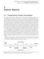
Private home base stations These offer a possibility of using the DECT sys-
tem in small private households (see Figure 9.1). The home base station
supplies the entire area of a house and can support one or several mobile
stations that are supplied by the base station. The home station con-
sists of a DECT fixed system (DFS), which controls the system, a simple
database (DB) for user administration and a fixed part (FP), which pro-
vides the radio supply to the mobile stations. An interworking unit
(IWU) is provided for connection to an external network [20].
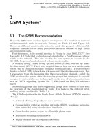
Wireless private branch exchanges In terms of installation, central systems
with a DFS to which several FPs are connected are suitable for large
private households or small companies (see Figure 9.2). Fixed terminals
can also be connected. The system is administered by the DECT fixed
system. The correct location area of the mobile stations is stored in
a database (DB), and an IWU enables a connection to the external
networks.
9.1 Possible Applications of DECT Systems 461
IWU
ISDN
PSTN
GSM
IWU
DB
= Portable PartPP
FP = Fixed Part
= Interworking Unit
= Data Base
PP
PP
FP
DB
DFS
DFS = DECT Fixed System
Figure 9.1: Private home base station
IWU
DB
ISDN
PSTN
GSM
FP
FP
PP
PP
DFS
Figure 9.2: Wireless private branch exchanges
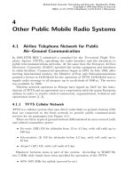
Public Telepoint systems These systems provide DECT mobile stations ac-
cess to the public telephone network over “other”FPs at public sites (see
Figure 9.3). Possible application areas are public facilities with high user
density such as airports, train stations and city centres. These private
and public DECT systems consist of a number of FPs that are admin-
istered by a DECT fixed system (DFS). Access to the public telephone
network can be provided by a network interface (With DECT, PPs in
principle can also be reached in the area of a Telepoint. The restriction
to outgoing calls is dictated by the respective licensing agreement).
Wireless local rings This is a ring to which a terminal adaptor (TA) and all
the terminals are linked (see Figure 9.4). The terminal adaptor pro-
vides a connection over the radio interface to one of the public FPs in
the area. The terminals (e.g., telephone, facsimile) are linked to the ter-
minal adaptor over conventional lines. If necessary, the terminal adaptor
462 9 DECT
ISDN
PSTN
GSM
PP
PP
FP
FP
Airport
Railway Station
FP
City Centre
IWU
DB
DFS
Figure 9.3: Public Telepoint system
TA
ISDN
PSTN
GSM
IWU
TA = Terminal Adapter
FP
DB
DFS
Figure 9.4: Wireless local rings
IWU
ISDN
PSTN
GSM
DB
FP
PP
PP
DFS
Figure 9.5: Neighbourhood Telepoint
establishes a radio connection to the next FP. The FP is administered
in the same way as with the public Telepoint service.
Neighbourhood Telepoint This is a combination of the public Telepoint ser-
vice and a private home base station (see Figure 9.5). Private households
do not have their own FP; instead one FP supplies a number of differ-
ent private households on the basis of the Telepoint principle. The FPs
9.1 Possible Applications of DECT Systems 463
IWU
SCU
SCU
Backbone
Ring
ISDN
PSTN
GSM
PP
PP
FP
FP
PP
PP
FP
FP
SCU = Subsystem Control Unit
DB
DFS
Figure 9.6: Private branch exchanges with ring and central DFS
are installed so that several households will always be supplied by one
FP. A DECT fixed system connected over a network interface with an
interworking unit (IWU) to the public telephone network manages the
FPs.
Because of the way they are designed in terms of size and subscriber capac-
ity, the following systems are also suitable for use by companies with scattered
operating locations. One or more nodes can be provided for DECT at each
company location. Each implementation of the system must be flexible and
tailored to the needs of the customer in each individual case.
Private branch exchanges with ring and central DFS These private branch
exchanges consist of a backbone ring with a number of switching nodes
(see Figure 9.6). Each switching node consists of a Subsystem Control
Unit (SCU) and several base stations, i.e., FPs. One of the nodes con-
tains the DFS which is responsible for all the nodes connected to the
backbone ring and controls them from a central function. The DFS also
contains the home database (HDB) and the interworking unit (IWU),
which constitutes the external connection. All signalling data transmit-
ted in this system must be transmitted over several nodes (SCUs) as
well as the backbone ring. Transmission channels of the network that
are no longer available for transporting user data are used for this pur-
pose. A disadvantage is that the entire network suffers if the central
system breaks down. Some relief is provided by the decentral systems,
which ensure that there is a reduction in signalling traffic and that only
464 9 DECT
SCU
IWU
SCU
Backbone
Ring
IWU
ISDN
PSTN
GSM
VDBHDB
VDBHDB
HDB = Home Data Base
VDB = Visitor Data Base
DFS
DFS
PP
PP
FP
FP
FP
FP
PP
PP
Figure 9.7: Private branch exchanges with ring and distributed DFS
the respective mobile stations are affected when the subsystem breaks
down [20].
Private branch exchanges with ring and decentral DFS These are set up
similarly to the systems with a central DFS (see Figure 9.7) and consist
of a backbone ring that interconnects a number of nodes. A control unit
is located at each of these nodes and several fixed stations are connected
to a node.
This system operates as a decentral structure because each control unit
is controlled by its own DECT fixed system. Furthermore, each DECT
fixed system has an interworking unit (IWU) that connects it to the
external networks. The data is also stored at decentral locations. Sub-
scriber administration is carried out in a home database (HDB), from
which important data for operations can be retrieved over the network.
For the purposes of reducing the signalling required when a mobile sub-
scriber is roaming the network, certain information about each sub-
scriber who moves out of the coverage area of his home database is
written to the visitor database (VDB) of the new coverage area. The
network provides access to the data in the visitor database, and the
backbone ring is unloaded of responsibility for the signalling. If a DFS
suffers a breakdown, only the subscribers moving in the respective cov-
erage area will be affected [20].
Private branch exchanges with direct connection of FP These branch ex-
changes have the same decentral structure as the decentral private
9.1 Possible Applications of DECT Systems 465
IWU
SCU
IWU
SCU
Backbone
Ring
ISDN
PSTN
GSM
VDBHDB
VDBHDB
PP
PP
PP
PP
DFS
DFS
FP
FP
FP
FP
Figure 9.8: Private branch exchanges with direct connection of FP
branch exchanges (see Figure 9.8). The difference between them is that
the fixed stations of these private branch exchanges are directly con-
nected to the respective DFS, which has the advantage that there is
a reduction in the signalling traffic within a node and consequently a
higher capacity for user data [20].
9.1.2 Data Storage
Databases can be set up in different ways. Three different types are presented
below:
SS 7-MAP The SS 7-MAP (Common Channel Signalling System Number 7,
Mobile Application Part) is a method used by public cellular networks
such as GSM900 and GSM1800. User data is stored in two registers:
a home location register (HLR) and a visitor location register (VLR).
Incoming calls are routed over the HLR to the VLR and from there to
the mobile terminal. Outgoing calls only use the VLR. Access of the
HLR is not required for these calls.
X.500 Another method is the storage of data based on the standardized reg-
ister service ITU-T X.500. The database is distributed physically over
different locations but logically centralized. The data therefore gives
the impression of being stored in a Directory Information Base (DIB).
All data is organized as objects in a hierarchical Directory Information
Tree (DIT), in which each branch can be filed in a physically separate
Directory System Agent. A Directory User Agent accesses the individual
466 9 DECT
objects. The search for the data takes place in a chain of interlinked
databases. A critical factor of this method is the time involved in access-
ing the data, but this is less of a problem for private branch exchanges
with a limit on subscriber numbers.
Telecommunication Management Network (TMN) A further method for
data storage is TMN based on ITU-T M.30. A management system
is controlled by a “manager” that realizes the management system using
objects containing important data. These objects are stored in a hierar-
chical MIB database (management information base). This MIB can be
distributed physically over different locations. The management system
is able to reproduce the HLR and VLR databases and store all location
area data in one object.
In comparison with public networks, only a limited number of users are
managed in private networks such as DECT branch exchanges. The data for
these users can usually be administered in one register. Moreover, it is easier
to change objects in the frequently changing organizational structure of office
environments than in conventional databases. This makes the HLR/VLR
concept less suitable for private branch exchanges than the other alternatives.
A comparison between X.500 and TMN shows that X.500 is more flexible
because it is not required to copy the HLR/VLR principle.
9.2 The DECT Reference System
The DECT Reference System describes the defined logical and physical com-
ponents of the DECT system, the interfaces between the different units and
the connection points to other networks. The global logical structuring of
a local DECT network is explained below. This is followed by examples of
different physical implementations.
9.2.1 Logical Grouping of DECT systems
The logical groups of the DECT network are organized according to their
functionalities with the intervening interfaces D1, D2, D3 and D4, which,
however, do not describe how they are physically implemented (see Figure 9.9).
9.2.1.1 Global Network
The global network supports the national telecommunication services. It
carries out address conversion, routing and relaying between the individual
connected socalled local networks. The global network is usually a national
(sometimes an international) network. Examples of local networks include:
• Public Switched Telephone Network (PSTN)
9.2 The DECT Reference System 467
DECT Network
D3
D3
D3 D3
Portable
Application
Portable
Application
Portable
Application
Portable
Application
Portable
Application
Portable
Application
Portable
Application
Portable
Application
Portable
Radio
Termin.
Portable
Radio
Termin.
Portable
Radio
Termin.
Portable
Radio
Termin.
Portable
Radio
Termin.
Portable
Radio
Termin.
Portable
Radio
Termin.
Portable
Radio
Termin.
D4
D4 D4 D4
D4
D4
D4 D4
Global Network
Local Network Local Network
Fixed
Radio
Termination
Fixed
Radio
Termination
Fixed
Radio
Termination
Fixed
Radio
Termination
D1
D1
D2 D2
HDB
VDB
HDB
VDB
D2
D2
Figure 9.9: DECT Reference System: Logical grouping
• Integrated Services Digital Network (ISDN)
• Packet Switched Public Data Network (PSPDN)
• Public Land Mobile Network (PLMN)
9.2.1.2 Local Networks
Each local network provides a local telecommunications service. Depending
on the actual installation, this can vary from a simple multiplexer to a highly-
developed complex network. If the subordinate DECT fixed radio termination
(FT) does not have a switching function then the local network must take over
this function. Yet it should be noted that there can be a difference between
logical definition and physical implementation, e.g., it is possible for several
networks with their functions to be combined into one unit.
A local network converts the global identification numbers (e.g., ISDN num-
bers) to the DECT-specific IPUI (International Portable User Identity) and
TPUI (Temporary Portable User Identity). The following networks are often
found under the local network:
• analogue or digital Private Automatic Branch Exchange (PABX)
• Integrated Services Private Branch Exchange (ISPBX)
• IEEE 802 LAN: local area network based on IEEE 802
All the typical network functions must be embedded outside the DECT
system and occur either in a local or in a global network. Similarly to GSM,
468 9 DECT
the HDB and VDB are required for controlling inter-DECT mobility, i.e., al-
lowing users to use their mobile stations to move within different independent
DECT areas (see Section 3.2.1.3). Incoming calls are automatically routed
to the subsystem in which the user is currently located. When a user moves
from one network to another, a new entry for the current VDB is made in the
HDB.
9.2.1.3 DECT Network
The DECT network consists of base and mobile stations, and connects users
to the local fixed network. No application processes are defined for the system,
and it only functions as a multiplexing facility. A DECT system always has
only one network address per user, i.e., mobile station, and (from a logical
standpoint) consists of one or more fixed radio terminations (FT) and many
portable radio terminations (PT) that have been allocated to it.
Fixed Radio Termination The FT is a logical grouping of all the functions
and procedures on the fixed network side of the DECT air interface. It is
responsible for:
• layer-3 protocol processes in the C-(control) layer (except for mobility)
• layer-2 protocol processes in the U-(user) layer
• layer-2 switching (routing and relaying) in the respective DECT network
Except for handover and multicell management, the FT contains no switch-
ing functions. Although it can manage a large number of call entities, it cannot
establish a direct connection between two users. This can only be carried out
outside the logically delineated area of the FT in the local network.
Portable Radio Termination and Portable Application These two parts con-
stitute the logical groups on the mobile side of the DECT network. Whereas
the portable radio termination with all its protocol elements for OSI layers 1, 2
and 3 is defined in the standard, it is up to the manufacturer of the equipment
to define the acceptable application. Therefore it is not standardized.
9.2.2 Physical Grouping of DECT Systems
Whereas the logical structure of the DECT network is clearly defined, the
physical grouping can assume different forms. It is adapted to each cus-
tomer’s requirements, and therefore can be conceptualized as a single base
station with up to 12 simultaneously communicating mobile stations if it is
equipped with one transceiver or as an independent switching centre for office
buildings. The logical interfaces D1, . . . ,D4 are thereby partially integrated
into a common physical unit and consequently can no longer be clearly ap-
portioned (see Figure 9.10).
9.2 The DECT Reference System 469
RFP
RFP
Manufacturer-
specific
groupings
REP
RFP
REP
DECT Portable Part
D3
DECT Fixed Part
Figure 9.10: DECT Reference System: physical grouping
9.2.2.1 DECT Base Station (Fixed Part)
Physically a DECT system can be split into two parts: a DECT fixed part
(FP) on the fixed side and a DECT portable part (PP) on the mobile side.
The fixed part on the wireline side can contain one or more logical groups of
the fixed radio termination with common control.
An FP can be divided into two physical subgroups:
• Radio Fixed Part (RFP): responsible for only one cell in the network
• Radio End Point (REP): corresponds to a transceiver unit in the RFP
9.2.2.2 DECT Mobile Device (Portable Part)
The two logical groups portable radio termination and portable application are
physically combined into one portable part (PP), typically a handset. A PP
normally only has one radio endpoint.
9.2.3 DECT Authentication Module (DAM)
A mobile station can be used by different users. Each user must identify
himself before being granted access to the DECT network. This function is
handled by a DECT Authentication Module (DAM), which contains informa-
tion for the identification (International Portable User Identity, IPUI) and
authentication (Authentication Key, K) of the user and can be inserted into
the PP. The DAM contains all the required encryption procedures.
9.2.4 Specific DECT Configurations
The DECT system description [5] lists several typical DECT configurations.
Different physical implementations are required, depending on the higher-
ranking network:
• PSTN • ISDN • X.25 • IEEE 802 LAN • GSM
Examples of possible installations are given below. Several suppliers are
already marketing private household systems at reasonable prices. Complex
470 9 DECT
private office installations are currently conquering the market. In addition,
DECT systems have been implemented and tested (since 1997) as Radio Local
Loop systems.
9.2.4.1 PSTN Reference Configuration
Domestic Telephone The private domestic telephone constitutes the sim-
plest DECT configuration. Here the network is connected to a PSTN over a
subscriber interface, just like a plain old telephone (POT) (see Figure 9.11).
The functional characteristics resemble those of the earlier CT 1 and CT 2
generations of cordless domestic telephones (see Chapter 8). There is no pro-
vision for a local network.
PBX Similarly to the domestic telephone, in a simple implementation of a
DECT-PBX, individual FPs are connected to the switching unit of the PSTN.
Technically it would then be very complicated to allow a changeover from one
FP to another FP during a call (handover).
In Figure 9.12 the fixed part contains several radio fixed parts, each of
which always serves one cell, thereby giving the system its cellular character.
A mobile station establishes a connection to the strongest RFP. If the user
is roaming in the area of a neighbouring cell, the FP is then in a position
of executing an internal layer-2 handover. The protocols for cell control are
controlled by the common control (CC) function, which physically can be
integrated into the FP or into the PBX.
Radio Local Loop A DECT system can also be incorporated as a local access
network into the PSTN (see Figure 9.13). In this case the radio connection is
transparent to the user. The user’s wireline telephone is linked to a Cordless
Terminal Adapter (CTA), which carries out the radio transmission to the
RFP. In the radio in the local loop (RLL) area, suppliers of fixed networks
are currently trying to avoid the high cost of local network cabling by using
DECT-RLL systems for the so-called last mile. A comparable configuration
using ISDN as the local fixed network and DECT as the RLL system is shown
in Figure 9.14.
9.2.4.2 GSM Reference Configuration
Aside from the X.25 reference configuration, which is not covered here, the
connection between the two mobile systems GSM and DECT should be men-
tioned. This development offers users the possibility of coupling a locally based
DECT system with the national GSM mobile radio system (see Figure 9.15).
From the standpoint of GSM, the portable application, PT, FT and possibly
also a local network form a mobile user unit. The D1 reference point is the
R reference point in the GSM standard (see Figure 3.3). Detailed coverage of
the integration of DECT and GSM systems is provided in Section 9.16.
9.2 The DECT Reference System 471
Global
Network
Fixed
Radio Term
Portable
Radio Term
Portable
Appl.
Local
Network
D1
D2
D3
D4
Example
Domestic
FP
PSTN POT
PSTN
Figure 9.11: Domestic telephone configuration
Global
Network
Fixed
Radio Term
Portable
Radio Term
Portable
Appl.
Local
Network
D1
D2
D3
D4
Example
PBX
Common
control
RFP
Fixed Part
PSTN PBX POT
PSTN
Figure 9.12: DECT-PBX configuration
Global
Network
Fixed
Radio Term
Portable
Radio Term
Portable
Appl.
Local
Network
D1
D2
D3
D4
Example
RFP
Fixed Part
Local
Exchange
Common
control
Cordless
Terminal Adapter
PSTN POT
Figure 9.13: Radio local loop configuration for PSTN
Global
Network
Fixed
Radio Term
Portable
Radio Term
Portable
Appl.
Local
Network
D1
D2
D3
D4
Example
RFP
Fixed Part
Local
Exchange
Common
control
Cordless
Terminal Adapter
PSTN
NT1 NT2 TE1
ISDN
Terminal
ISDN
Terminal
ISPBX
T SU
Figure 9.14: Radio local loop configuration for ISDN
472 9 DECT
Global
Network
Fixed
Radio Term
Portable
Radio Term
Portable
Appl.
Local
Network
D1
D2 D3 D4
BSS
TE
TA
MT
A
U
m
S R
MSC
Example
BSS
MSC
DECT / GSM
Converter
Figure 9.15: GSM-DECT configuration
9.3 The DECT Reference Model
The DECT reference model was designed in accordance with the ISO/OSI
model (see Section 2.5). Because the DECT system incorporates the interface
between communicating partners, only certain aspects of the applications-
oriented layers are included in the standard, e.g., encryption.
The key functions of the DECT system correspond to the three lower layers
of the ISO/OSI model: Physical, Data Link and Network layers. Because
with DECT the quality of the transmission medium (radio) is continuously
changing and channel access is a complicated function that must be carried
out frequently, the data link layer has been divided into the two sublayers Data
Link Control (DLC) and Medium Access Control (MAC). Figure 9.16 relates
the DECT reference model to the corresponding ISO/OSI layers. Above the
MAC layer the functions of the layers are grouped into two parts: the Control
plane for signalling and the User plane for the transmission of user data. The
control functions of the C-plane are processed in the network layer, whereas
the data of the U-plane is passed on unprocessed.
9.3.1 An Overview of Services and Protocols
The DECT layers with their characteristics are briefly introduced below. A
detailed description of the DECT layers is provided in Section 9.4.
9.3.2 Physical Layer (PHL)
The physical layer (PHL) is responsible for implementing the transmission
channels over the radio medium. At the same time it has to share the medium
with many other mobile stations that are also transmitting. Interference and
collisions between communicating base and mobile stations are largely avoided
thanks to the decentrally organized use of the available dimensions location,
time and frequency (see Figure 9.17). Each dimension contains several possi-
bilities for seizing a channel for interference-free transmission.
The TDMA (Time-Division Multiple-Access) method is the one used for
the time dimension. Each station sets up its channel in any available time slot
9.3 The DECT Reference Model 473
✁
✂
✄ ☎
✆
✝✞
✟
✁
✂
✄ ☎
✆
✝✞
✠
✁
✂
✄ ☎
✆
✝✞
✡
U-Plane
Lower Layer
Management
Entity
Application Process
Process
C-Plane
Interworking
Signalling
Application
Layer
Control
Network
Physical Layer
Medium-Access Control Layer
Layer
Data Link
Layer
Control
Data Link
Figure 9.16: DECT reference model
and is then able to transmit in that time slot at a constant bit rate. Because
of the TDD (Time-Division Duplexing) method the uplink and downlink of
this channel are in slot pairs on the same frequency. Consequently a duplex
transmission always occupies two time slots, which are separated from another
by a fixed interval.
The FDMA (Frequency-Division Multiple-Access) method with 10 different
frequencies is used for the frequency dimension. This means that each station
is able to select and occupy a slot pair on any frequency for its transmission.
Owing to the attenuation of the propagation of the radio waves, frequencies
and time slots can be reused at appropriate distances. These resources are
occupied based on a dynamic procedure for channel selection that takes into
account the local traffic load on the system.
Key technical data for the DECT system is listed in Table 9.1 (see
also Table 8.2). With only 12 duplex voice channels in 1.73 MHz, i.e.,
144 kHz/channel pair, DECT is very generous in its use of spectrum (GSM
only requires 50 kHz/channel pair). However, because of its dynamic channel
selection, the resulting small random reuse distances and the microcellular
coverage, DECT provides a much higher capacity (Erl./km➨), producing al-
most unbelievably high values (10 kErl./km➨), especially in high-rise buildings
because of the reuse distances at every two levels over the same base area.
474 9 DECT
Frequency
Time
Slot
B
BS 1
Space
Frequency
Time
Slot
B
BS 2
Figure 9.17: Three-dimensional use of spectrum
Table 9.1: Physical data on the DECT system
Frequency band 1880–1900 MHz
No. of carrier frequencies 10
Carrier spacing 1.728 MHz
Max. transmitter power 250 mW
Carrier multiplexing TDMA
Basic duplex method TDD
Frame length 10 ms
No. of slots (frame) 24
Modulation GFSK with BT = 0.5/GMSK
Modulated overall bit rate 1152 kbit/s
Net data rate 32 kbit/s data (B-field) unprotected
for standard connections 25.6 kbit/s data (B-field) protected
6.4 kbit/s signalling (A-field)
9.3.3 Medium-Access Control (MAC) Layer
The MAC layer (Medium-Access Control (MAC) Layer ) (see Figure 9.16) is
responsible for setting up, operating and releasing channels (Bearer) for the
higher layers. The different data fields of the MAC protocol are protected by
cyclical codes, which are used for error detection at the receiver. The MAC
layer ensures that service-specific control data is added to each time slot.
The MAC layer comprises three groups of services:
9.3 The DECT Reference Model 475
BMC The Broadcast Message Control Service is offered on at least one phys-
ical channel in each cell, even if there is no user transmitting. This
channel is called a beacon channel, and produces a continuous connec-
tionless point-to-multipoint connection on the downlink in which a base
station transmits its system-related data. This identifies the base sta-
tion to the mobile unit. By evaluating the received signal, the terminal
can determine the current channel quality at the same time.
CMC The Connectionless Message Control Service supports a connection-
less point-to-point or point-to-multipoint service that can be operated
bidirectionally between a base station and a mobile user.
MBC The Multi-Bearer Control Service offers a connection-oriented point-
to-point service. An entity transmitting in one or both directions is able
to support several bearers, thereby achieving a higher net data rate.
Each of these three services incorporates its own independent service access
point (SAP), which links it to the next-highest layer and can combine several
logical channels together.
9.3.4 Data Link Layer
The protocol stack directly above the MAC layer divides into two parallel
parts. Similarly to the MAC layer, extensive error protection in the C-plane
of the data link layer improves the reliability of the data transmission. Along
with a point-to-point service, the C-plane offers a broadcast service to the
network layer above it. The U-plane is responsible for processing user data on
the radio section, with the spectrum of services ranging from the transmission
of unprotected data with minimal delays, e.g., speech, to the provision of
protected services with variable delays for data transmission. The required
data rate of an existing connection can be changed at any time.
9.3.5 Network Layer
The network layer sets up, manages and terminates connections between users
and the network. The U-plane in DECT has no role in the network layer and
forwards all data unprocessed in a vertical direction. The C-plane carries out
the signalling and is responsible for controlling data exchange. Five protocols
based on the link control entity are provided for this purpose. Along with
the call and connection entities, there is a mobility management service that
carries out all the tasks necessary to support the mobility of mobile stations.
In addition to the data for location area management, messages for authenti-
cation and encryption data are also transmitted.
476 9 DECT
9.3.6 Management of the Lower Layers
The management of layers 1–3 (Lower Layer Management Entity (LLME) (see
Figure 9.16) contains procedures that affect several protocol layers. Processes
such as generating, maintaining and releasing physical channels (Bearers) are
initiated and controlled from this entity. Furthermore, the LLME selects
from the physical channels which are available and evaluates the quality of
the received signal.
9.4 Detailed Description of Services and
Protocols
9.4.1 Physical Layer (PHL)
A physical channel is the physical transmission path between two radio units.
Radio transmission places a great demand on transceivers to ensure that there
is good reception of the usage signal. The receiver sensitivity for the required
bit error ratio (BER) of 0.001 is −83 dBm (60 dB➭V/m) [8]. This was in-
creased to −86 dBm for applications run by public services [13]. In DECT a
normal telephone connection requires two independent channels between the
device end points on the transmission medium radio.
9.4.1.1 FDMA and Modulation Techniques
Because of FDMA access, the DECT system has the possibility of selecting
from a number of frequencies in its channel selection.
It operates in the 1880–1900 MHz frequency band. Within this band 10
carrier frequencies are defined, the mid-frequency f
c
of which can be calculated
as follows:
f
c
= f
0
− c · 1728 kHz, with c = 0, 1, . . . , 9 and f
0
= 1897.344 MHz (9.1)
In an active state the deviation from the mid-frequency should be a maximum
of ±50 kHz.
The modulation techniques used are either Gaussian Frequency Shift Key-
ing (GFSK) with a bandwidth–time product BT = 0.5 or Gaussian Minimum
Shift Keying (GMSK).
If a transmit signal is formed from two orthogonal bandpass signals with dif-
ferent mid-frequencies, this is referred to as Frequency Shift Keying (FSK). A
Gaussian filter acting as a low-pass filter (GFSK) removes the high-frequency
parts of the signal in order to keep the band of the signal’s spectrum as small
as possible. If the modulation index is 0.5 and the possibility of a coherent
demodulation of the radio signal exists, this shift procedure is referred to as
minimum-shift keying (MSK). With GMSK the Gaussian filter also comes
into play. For cost reasons, receivers in DECT systems are usually not built
with coherent demodulation/modulation [27].
9.4 Detailed Description of Services and Protocols 477
f479f0
✂✁☎✄✝✆✟✞
✠☛✡✌☞✎✍ ✏☛✑✓✒✕✔✗✖☛✖✙✘☎✠☛✚✌✛☎✜ ✑☎✔✢✖✙✚✤✣✌✒
✥✧✦
✍ ✜ ★☎✩
✪
✏☎✫✬✑✓✭☎✛☛✍ ✮✤✯✰✫✬✭☎★☎✒✱✣✌✜ ✑
✲✌✲ ✲✤✳✲✵✴✲✌✶✴✸✷✴✺✹✴✸✻✴✺✼✴✺✽✴✸✾✴✺✳✴✸✲✴✤✴✴✸✶✷✹✼ ✻✽✾✳✲✴✶
✿❀✿ ✿❀✿
❁
✏☎❂✧★☎✍ ✜ ★☎✩
❃
✭☎✒✱✮✌✯✰✫✬✭☛★☎✒✱✣✌✜ ✑
✠☎✡☎✚✤✛☎✜ ✑ ✠☎✡☛✚✌✛☎✜ ✑ ✠☛✡☎✚✌✛☛✜ ✑ ✠☛✡☎✚✌✛☛✜ ✑ ✠☎✡☎✚✤✛☎✜ ✑✠☎✡☎✚✤✛☎✜ ✑
✡☎❄☎✚✤✛☎✜ ✑ ✡☎❄☛✚✌✛☎✜ ✑
❅❇❆
✍ ✍✱☞✎✍ ✏☎✑☛✠☎✩
❅❈❆
✍ ✍❉☞✎✍ ✏☎✑☎✠☎✩✱❊✎✖
❅❇❆
✍ ✍✱☞✎✍ ✏☎✑☛✠☎✩✱❋❀✖
●✗❍✸■ ❏✤❑▲■◆▼❖ ●◗❍✸■ ❏✤❑❘■◆▼❖
❙❯❚ ❙✕❱ ❙✂❚
●◗❍✸■ ❏✤❑❘■❲▼❖ ●◗❍✸■ ❏✤❑❘■❲▼❖ ●✗❍✸■ ❏✤❑❘■❲▼❖ ●✗❍✸■ ❏✤❑▲■◆▼❖
❙✕❱
❁
✏
❆
✛☎✍ ✮✌☞✎✍ ✏☛✑☎❳☎❨☛✚✌✛☎✜ ✑
❯❩☎❬✸❭◆❪❴❫✕❩❛❵✟❜✎❝ ✆❞✄❴❡✱❢✝❢ ❣❤✄✝❜✎❝ ✆✐❫✕❩❛❵✟❜✎❝ ✆✟✄✸❡✱❥✝❦
b0
b419b95
❧✐♠☎✄❴❭◆♥
b424 b479
♦q♣❈r✸s✉t
♦q✈①✇②✇
③
✇②④✧⑤
❙❯❚
❙✕❱
L LL L LL
Figure 9.18: Time-multiplex elements of the physical layer
The transmission of a binary 1 in a DECT system produces a frequency
increase of f = 288 kHz to f
c
+ 288 kHz. For the transmission of a 0 the
frequency is decreased by f to f
c
− 288 kHz.
The standard does not provide for any equalizers. With a bit duration of
0.9 ➭s, waves that reach the receiver with a delay due to multipath propagation
(see Figure 2.8) cause signal dispersion (see Section 2.1.7), which with a 300
m alternative path length already corresponds to the symbol duration and
makes reception impossible even when sufficient signalling power exists. The
literature recommends using 16 of the 32 synchronization bits in the S-field in
accordance with Figure 9.19 to estimate the impulse response of a channel in
the receiver, which equates to a good (but not one conforming to the standard)
implementation of an equalizer [21].
9.4.1.2 TDMA Technique
Each station receives a protected, periodically recurring portion of the overall
transmission rate of a frequency. According to Figure 9.18, the frame and
time slot structure of the DECT system is explained in the physical layer.
The transmission capacity of each frequency is divided into 10 ms long
periodically recurring frames, each of which has a length corresponding to
the duration of 11.520 bits. This produces a gross frame transmission rate of
1152 kbit/s. A frame comprises 24 time slots, which are used as either full
slots, double slots or half slots (see Figure 9.18).
In a normal basic connection the first 12 time slots are used for transmitting
data from the base station to a mobile station (downlink ), whereas the second
part of the 24 slots is reserved for the direction from the mobile station to the
base station (uplink). Since a duplex connection requires both an uplink and a
478 9 DECT
✁✄✂ ✁✆☎✆✝✞✁✆☎✄✟
✠
✂
✡☞☛✄✌✎✍✑✏✄✒✓✡✓✔
✂
✕✗✖✙✘
✠✛✚✢✜✆✚
✁
✚
✂✆✣✁
✔
✚✆✚
✠
✣✓✤
✚✠
✂
✁✄✂ ✁✆☎✆✝✞✁✆☎✄✟ ✁✆✝✆✤
✚
✁✄✂ ✁✆☎✄✟ ✁✆✝✆✤
✚
✠
✟✓☎
✚
✥✧✦✆★ ★✑✩✓★ ✪✄✒
✕✗✘✫✖ ✕✬✘✙✖
✁✆✝
✔
✣ ✁✆✝
✔
✣
✕
✁✄✂ ✁✢☎✆✝✞✁✆☎✄✟
✡☞☛✭✌✧✍✑✏✄✒✮✡
✂✆✂
✁
✚✆✜
✠
✣✓✤
✚✠
✂
✁✄✂ ✁✢☎✆✝✞✁✆☎✄✟
✠
✣✓✤
✚✠
✂
✥✧✦✆★ ★✑✩✓★ ✪✄✒
✡✓☛✄✌✧✍✯✏✄✒✓✡
☎✄✟
✁✄✣✓✝
✚
✁✄✣✆✟✢✣
✕✗✰✙✱
✲✳☛✆★
✠
✩☞★ ✪✄✒✵✴
✝
✥✧✦✆★ ★✑✩✓★ ✪✄✒
✶✳✪✆✦✆✷✢★ ✏✸✩✓★ ✪✭✒
✡✓☛✄✌✧✍✯✏✄✒✓✡
✂
✔✄✹✧✺✻✴
✂✓✼
✡☞☛✄✌✎✍✑✏✄✒✓✡
✂
✔✄✹✧✺✽✴
✂✓✼
✁✆☎✆✝
✲✳☛✆★
✠
✩☞★ ✪✄✒✵✴
✂
L
k
k
k
k
L
j j
Figure 9.19: The different physical packets in the DECT standard
downlink connection, the DECT system uses a technique called Time-Division
Duplexing (TDD). If the base station occupies slot k in order to transmit to
the mobile unit, slot k + 12 is reserved for the mobile station to enable it to
send data to the base station. This rigid system of allocation is abandoned
when it comes to more complex advanced connections, where a generous use
of time slots is allowed in each transmission direction.
Each of the 24 time slots has a length of 480 bits (416 ➭s) and can be used
in accordance with the slot type (full, half, double). Different physical packets
are based on this structure. Each physical packet contains a synchronization
field S and a data field D. A physical packet is shorter than a time slot by
one guard period to prevent an overlapping of packets from neighbouring time
slots.
A P00 (short physical packet) is used for short connectionless transmissions
in the beacon channel or for short messages. It comprises only 96 of the
480 bits and therefore provides a particularly large guard time in a slot. This
is especially important at the start of a connection phase when a mobile
station is not yet completely synchronized with the network and could cause
interference to neighbouring time slots when it transmits a full slot.
A P08j message only requires a half slot for transmission, and therefore
because of the decreased transmission rate ends up with double the number
of available channels per frame; see Figure 9.19.
Because full slots are usually the ones preferred when a slot is requested,
the packet P32 will be described here. The first 32 bits form the synchroniza-
tion field S, which is used for clock and packet synchronization in the radio
network. It consists of a 16-bit preamble, followed by a 16-bit long packet
synchronization word. In the S-field the response from the mobile station
contains the inverted sequence of the bit of the synchronization field sent by
the base station.
9.4 Detailed Description of Services and Protocols 479
✂✁☎✄✝✆
✞✠✟✠✡☞☛✍✌☎✎✂✏☎✄✝✑✂✌☎✒✝✓
✔✕✄✝✆✖✌✂✗☎✘ ✙ ✄✝✑✂✓☎✏
✟✛✚✍✙ ✆✖✜✝✑✣✢✥✤✦✤
✧★✙ ✩☞✄✝✆
✪✫✩☞✌✂✤✖✤✖✙ ✜✭✬✍✑☎✌☎✎✂✎☎✓☎✘
✪✫✩☞✌✂✤✖✤✖✙ ✜✭✬✍✑☎✌☎✎✂✎☎✓☎✘ ☎✌☎✄✮✆
✯✰✓☎✘ ✓☎✌☎✄✮✓☎✏
✧★✁✂✱☎✎☎✏✣✞✠✟✟✠✚✍✙ ✆✦✜✝✑✲✢✭✎
Idle
Locked
Active
Unlocked
Unlocked
Active
Locked
Idle
Figure 9.20: Operating states of a mobile station
The S-field is followed by the user data field D, which is 388 bits long.
Some of the content of this field is evaluated by the MAC layer, and therefore
will be covered in detail later (see Section 9.4.2.5).
The possibility of transmitting a so-called Z-field is offered by the D-field.
This 4-bit long word contains a copy of the last 4 bits of the data field, which
is also referred to as an X-field. A comparison of these two areas allows the re-
ceiver to establish whether a transmission is being disrupted because of errors
in the synchronization of neighbouring DECT systems. These disruptions are
referred to as sliding collisions within the system. A measurement of these
disruptions results in the early detection of interference, and can be used as
the criterion for an optimal handover decision. Packet P80 is the one with the
highest data rate, and requires a double slot. User data rates up to 80 kbit/s
can be achieved with this packet.
9.4.2 Medium-Access Control (MAC) Layer
9.4.2.1 Operating States of a Mobile Station
With reference to the MAC layer [9], a mobile station can find itself in one of
the four states shown in Figure 9.20.
• Active Locked The synchronized mobile station has at least one con-
nection to one or more base stations.
• Idle Locked The mobile station is synchronized with at least one base
station. It currently does not have a connection, but is in a position to
receive requests for connections.
• Active Unlocked The mobile station is not synchronized with any base
station, and therefore cannot receive any requests for connections. It
attempts to find a suitable base station for synchronization to enable it
to move into the Idle Locked state.
• Idle Unlocked The mobile station is not synchronized with any base
station, and is not in a position to detect base stations that are suitable.
480 9 DECT
Idle
Active
Traffic
and Idle
Act. Traffic
Active
Last
released
First
Traffic Channel
established
Traffic Channel
Channel established
and Dummy Bearer
released
Dummy Bearer
Last Traffic
First Traffic Channel
established and
Dummy Bearer
released
Dummy Bearer
released
established
Figure 9.21: States of a base station
If a terminal is switched off, it is in the Idle Unlocked state. When it is
switched on, a mobile station tries to transit to the Idle Locked state. It
begins to search for a suitable base station with which to synchronize. If it
is successful, a transition to the Idle Locked state is made. In this state a
mobile station is able to receive or transmit requests for connection. As soon
as the first traffic channel is set up, it changes over to Active Locked state.
If the last channel is cleared after the termination of a connection, the mobile
station returns to the Idle Locked state. If it loses its synchronization with
the base station, it must change to the Active Unlocked state and seek a
new suitable base station.
9.4.2.2 Operating States of a Base Station
A base station can find itself in one of four states. The Inactive state in
which a base station is switched off is not shown in Figure 9.21.
• Inactive The base station is switched off and can neither receive nor
transmit messages.
• Active Idle The base station is not operating a traffic channel, and
therefore radiates a dummy bearer that the mobile receivers are able to
detect when observing the physical channels.
• Active Traffic The base station operates at least one traffic channel.
The dummy bearer is no longer supported.
• Active Traffic and Idle The base station maintains a dummy bearer
in addition to at least one traffic channel (traffic bearer).
In the basic state Active Locked, the base station transmits a dummy
bearer in order to enable mobile terminals to synchronize with its frame and
slot clock. If a traffic bearer is established, the base station moves into Active
9.4 Detailed Description of Services and Protocols 481
✁ ✄✂
✂✆☎✞✝✠✟☛✡✌☞ ✍✞✝✞✎
✁✏ ☎✞✎☛✡✒✑✞✓✔ ✁✍✞✝✠✡✌✓✕✍✞✏
✁✖✗✂ ✁✖✗✂
✁✑✠✏ ✏☛✖✘☞ ✡✌✑
✂✆☎✞✝✠✟☛✡✌☞ ✍✞✝✞✎ ✂✆☎✠✝✞✟☛✡✌☞ ✍✞✝✞✎
✁✖✗✂
✂✆☎✞✝✞✟✙✡✌☞ ✍✠✝✞✎
✁✑✞✏ ✏☛✖✘☞ ✡✌✑ ✚✑✠✏ ✏✙✖✘☞ ✡✌✑
✛✢✜✘✣
✖
✜✗✤
✛✦✥✘✣
✖
✜✗✤
✛
✣
✖
✜✗✤
✤★✧✁✩ ✤★✧✁✩ ✤★✧✁✩
✪✫✣
✖
✜✗✤ ✪✫✣
✖
✜✗✤✪✫✣
✖
✜✗✤
✬✭✯✮
✰✱
✲
Figure 9.22: Classification of MAC services
Traffic state. The dummy bearer can then be eliminated. The transition on
the opposite side takes place after the last traffic channel has been released. If
a dummy channel is required when the traffic bearer is transmitted, the base
station can move into Active Traffic and Idle state. Again the dummy
bearer can be retained when the first traffic channel is set up. A transition is
then made from Active Idle to Active Traffic and Idle.
9.4.2.3 Cell and Cluster Functions
The MAC layer functions have already been covered in the overview in Sec-
tion 9.3.3. This layer is used to set up and manage the traffic channels
(bearers) requested from the LLME and, when requested, to release them.
The control information, which is introduced through different service access
points in the MAC layer, is multiplexed and added to the actual user data in
each time slot.
The different services of the MAC layer are divided into two groups (see
Figure 9.22). The cluster control functions in the upper area are linked to the
data link layer through the three service access points MA, MB and MC. The
cell site functions in the lower part coordinate the transition to the physical
layer. The two groups offer the following individual functions:
Cluster Control Functions (CCF) These functions control a cluster of cells.
Each logical cluster of cells contains only one CCF, which controls all the cell
site functions (CSF). Three different independent services are available within
this cluster:
482 9 DECT
✂✁☎✄ ✆✞✝ ✟☎✄ ✠☛✡
☞✍✌✎☞
✏✁☛✄ ✆✑✝ ✟☛✄ ✠☛✡
✂✁☛✄ ✆✞✝ ✟☎✄ ✠☛✡
✒✔✓✖✕✗✕
✘✚✙ ✛✜✓
✢✤✣✤✥✧✦
✛★✙ ✩
✥✫✪
✬
✒✔✘
✢✫✭
☞✍✌✎☞
☞✍✌✎☞
✮
✌✎☞
✂✁☎✄ ✆✞✝ ✟☎✄ ✠☛✡
✯✞✰
☞
✂✁☛✄ ✆✞✝ ✟☎✄ ✠☛✡
☞✍✌✎☞
✂✁☎✄ ✆✞✝ ✟☎✄ ✠☛✡
✱
✌✎☞
✏✁☛✄ ✆✑✝ ✟☛✄ ✠☛✡
✲✴✳
✲
✵
✶
✷ ✸
✹ ✺✧✻
✹✹
✺
✶
✺✧✻
✺
✬
✒✼✒
✢✫✭
✢✍✣✤✥✫✦
✛★✙ ✩
✥✫✪
✒✽✩
✥
✛★✾✿✩❀✕
❁❃❂✧❄✞❅★❂✧❆ ❁❈❇☎❄✞❅★❂✧❆ ❁❊❉❋❄✞❅★❂✧❆
❁❈●☎❄✞❅★❂✧❆
❍❋❄✞❅★❂✧❆★■
✶❑❏
✲
✳
❏
✲
✵
✒✼✕
✣✫✪
✛▲✓✖✾
✌
✠☛▼☎◆❖✠☛◆
✏✁☛✄ ✆✞✝
☞✍◗☛❘
✆✞◆
◗
✄
✌
◆
◗
▼☛❙☛❚❯▼☛❱❯✆
✂✠☎❱❲❱❯▼☛❳☛✠
☞✍◗☛❘
✆✑◆
◗
✄
☞✍◗☎❘☛❘
✠☛❚❯✆✞✝
◗☎❘
✄ ✠☎❱❲❱
✂✠☎❱❲❱❯▼☛❳☛✠
☞✍◗☛❘
✆✑◆
◗
✄
Figure 9.23: Overview of services and channels in the MAC layer
Broadcast Message Control (BMC) This function only exists once in each
CCF, and distributes the cluster broadcast information to the respective
cell functions. The BMS supports a number of connectionless point-to-
multipoint services, which are directed from a base station to the mobile
station. The BMC works with any type of traffic channel. An important
service is the paging of mobile stations.
Connectionless Message Control (CMC) All information that concerns the
connectionless service is usually controlled by one CMC in each CCF. In
addition to transmitting information from the control level of the DLC
layer, the CMC also processes user data from the so-called U-plane. The
services can be operated in both directions.
Multi-Bearer Control (MBC) This service comprises the management of all
data that is exchanged directly between two corresponding MAC layers.
An MBC capable of organizing several traffic channels exists for each
connection-oriented point-to-point connection.
Cell Site Functions (CSF) These functions appear below the CCF services
in the MAC layer, and stand in for the respective cell. Therefore several
CSFs are controlled by each CCF. The following cell-oriented services are
differentiated (see Figure 9.23):
Connectionless Bearer Control (CBC) Each connectionless bearer within
the CSF is controlled by its own CBC.
9.4 Detailed Description of Services and Protocols 483
Dummy Bearer Control (DBC) Each CSF has a maximum of two dummy
bearers to provide a beacon function for the synchronization of the mo-
bile stations in the event that no user connection exists in the cell.
Traffic Bearer Control (TBC) An MBC must request a TBC for a duplex
connection.
Idle Receiver Control (IRC) This service controls the receiver in a cell when
no connection is being maintained to a user; a cell can have more than
one receiver, and consequently a related number of IRC services.
9.4.2.4 Service Access Points
The cluster and cell-oriented functions include several service access points
(SAP), which can be used by the MAC layer entities to communicate with
the next-highest OSI layer (data link control layer) and the next-lowest OSI
layer (physical layer) (see Figure 9.22). The following SAPs are available
between the CCF and the DLC layers:
• MA-SAP • MB-SAP • MC-SAP
Each cell-specific service has its own D-SAP for access to the physical layer.
The MAC layer has a separate SAP, the ME-SAP, to support the lower layer
management functions. This SAP is not formally specified, and therefore has
no logical channels.
MA-SAP Information from the Broadcast Message Control Service is trans-
mitted to the DLC layer over this access point. Data from the B
S
channel as
well as control data that controls the data flow on the B
S
channel is transmit-
ted. This logical Higher-Layer Broadcast Channel supports a connectionless
simplex broadcast service from the base station to the mobile station.
MB-SAP This access point links Connectionless Message Control with the
DLC layer, and contains four logical channels:
• CL
F
• CL
S
• SI
N
• SI
P
The control channels CL
F
and CL
S
support a connectionless duplex service
between the base station and the mobile terminal. A continuous service exists
from the base station to the mobile station but not in the opposite direction.
The quantity of data permitted on the CL
S
channel is 40 bits, which corre-
sponds to the segment length of this channel. The fast CL
F
channel has a
permitted segment length of 64 bits, and the quantity of data can amount to
four times the segment length.
The information channels SI
N
/SI
P
offer an unprotected/protected simplex
service from the base station to the mobile station.