Tài liệu Low-Power, Slew-Rate-Limited RS-485/RS-422 Transceivers doc
Bạn đang xem bản rút gọn của tài liệu. Xem và tải ngay bản đầy đủ của tài liệu tại đây (830.6 KB, 20 trang )
For pricing, delivery, and ordering information, please contact Maxim/Dallas Direct! at
1-888-629-4642, or visit Maxim’s website at www.maxim-ic.com.
General Description
The MAX481, MAX483, MAX485, MAX487–MAX491, and
MAX1487 are low-power transceivers for RS-485 and RS-
422 communication. Each part contains one driver and one
receiver. The MAX483, MAX487, MAX488, and MAX489
feature reduced slew-rate drivers that minimize EMI and
reduce reflections caused by improperly terminated cables,
thus allowing error-free data transmission up to 250kbps.
The driver slew rates of the MAX481, MAX485, MAX490,
MAX491, and MAX1487 are not limited, allowing them to
transmit up to 2.5Mbps.
These transceivers draw between 120µA and 500µA of
supply current when unloaded or fully loaded with disabled
drivers. Additionally, the MAX481, MAX483, and MAX487
have a low-current shutdown mode in which they consume
only 0.1µA. All parts operate from a single 5V supply.
Drivers are short-circuit current limited and are protected
against excessive power dissipation by thermal shutdown
circuitry that places the driver outputs into a high-imped-
ance state. The receiver input has a fail-safe feature that
guarantees a logic-high output if the input is open circuit.
The MAX487 and MAX1487 feature quarter-unit-load
receiver input impedance, allowing up to 128 MAX487/
MAX1487 transceivers on the bus. Full-duplex communi-
cations are obtained using the MAX488–MAX491, while
the MAX481, MAX483, MAX485, MAX487, and MAX1487
are designed for half-duplex applications.
________________________Applications
Low-Power RS-485 Transceivers
Low-Power RS-422 Transceivers
Level Translators
Transceivers for EMI-Sensitive Applications
Industrial-Control Local Area Networks
____________________________Features
♦ In µMAX Package: Smallest 8-Pin SO
♦ Slew-Rate Limited for Error-Free Data
Transmission (MAX483/487/488/489)
♦ 0.1µALow-Current Shutdown Mode
(MAX481/483/487)
♦ Low Quiescent Current:
120µA (MAX483/487/488/489)
230µA (MAX1487)
300µA (MAX481/485/490/491)
♦ -7V to +12V Common-Mode Input Voltage Range
♦ Three-State Outputs
♦ 30ns Propagation Delays, 5ns Skew
(MAX481/485/490/491/1487)
♦ Full-Duplex and Half-Duplex Versions Available
♦ Operate from a Single 5V Supply
♦ Allows up to 128 Transceivers on the Bus
(MAX487/MAX1487)
♦ Current-Limiting and Thermal Shutdown for
Driver Overload Protection
Ordering Information
Ordering Information continued at end of data sheet.
*Contact factory for dice specifications.
MAX481/MAX483/MAX485/MAX487–MAX491/MAX1487
Low-Power, Slew-Rate-Limited
RS-485/RS-422 Transceivers
________________________________________________________________ Maxim Integrated Products 1
______________________________________________________________Selection Table
19-0122; Rev 7; 6/03
PART TEMP RANGE PIN-PACKAGE
MAX481CPA
0°C to +70°C 8 Plastic DIP
MAX481CSA 0°C to +70°C 8 SO
MAX481CUA 0°C to +70°C 8 µMAX
MAX481C/D 0°C to +70°C Dice*
MAX481
MAX483
MAX485
MAX487
MAX488
MAX489
MAX490
MAX491
MAX1487
PART
NUMBER
HALF/FULL
DUPLEX
DATA RATE
(Mbps)
SLEW-RATE
LIMITED
LOW-POWER
SHUTDOWN
RECEIVER/
DRIVER
ENABLE
QUIESCENT
CURRENT
(µA)
NUMBER OF
TRANSMITTERS
ON BUS
PIN
COUNT
Half
Half
Half
Half
Full
Full
Full
Full
Half
2.5
0.25
2.5
0.25
0.25
0.25
2.5
2.5
2.5
No
Yes
No
Yes
Yes
Yes
No
No
No
Yes
Yes
No
Yes
No
No
No
No
No
Yes
Yes
Yes
Yes
No
Yes
No
Yes
Yes
300
120
300
120
120
120
300
300
230
32
32
32
128
32
32
32
32
128
8
8
8
8
8
14
8
14
8
MAX481/MAX483/MAX485/MAX487–MAX491/MAX1487
Low-Power, Slew-Rate-Limited
RS-485/RS-422 Transceivers
2 _______________________________________________________________________________________
ABSOLUTE MAXIMUM RATINGS
Supply Voltage (V
CC
).............................................................12V
Control Input Voltage (RE, DE)...................-0.5V to (V
CC
+ 0.5V)
Driver Input Voltage (DI).............................-0.5V to (V
CC
+ 0.5V)
Driver Output Voltage (A, B)...................................-8V to +12.5V
Receiver Input Voltage (A, B).................................-8V to +12.5V
Receiver Output Voltage (RO).....................-0.5V to (V
CC
+0.5V)
Continuous Power Dissipation (T
A
= +70°C)
8-Pin Plastic DIP (derate 9.09mW/°C above +70°C) ....727mW
14-Pin Plastic DIP (derate 10.00mW/°C above +70°C) ..800mW
8-Pin SO (derate 5.88mW/°C above +70°C).................471mW
14-Pin SO (derate 8.33mW/°C above +70°C)...............667mW
8-Pin µMAX (derate 4.1mW/°C above +70°C) ..............830mW
8-Pin CERDIP (derate 8.00mW/°C above +70°C).........640mW
14-Pin CERDIP (derate 9.09mW/°C above +70°C).......727mW
Operating Temperature Ranges
MAX4_ _C_ _/MAX1487C_ A ...............................0°C to +70°C
MAX4_ _E_ _/MAX1487E_ A.............................-40°C to +85°C
MAX4_ _MJ_/MAX1487MJA ...........................-55°C to +125°C
Storage Temperature Range .............................-65°C to +160°C
Lead Temperature (soldering, 10sec) .............................+300°C
DC ELECTRICAL CHARACTERISTICS
(V
CC
= 5V ±5%, T
A
= T
MIN
to T
MAX
, unless otherwise noted.) (Notes 1, 2)
Stresses beyond those listed under “Absolute Maximum Ratings” may cause permanent damage to the device. These are stress ratings only, and functional
operation of the device at these or any other conditions beyond those indicated in the operational sections of the specifications is not implied. Exposure to
absolute maximum rating conditions for extended periods may affect device reliability.
V
V
IN
= -7V
V
IN
= 12V
V
IN
= -7V
V
IN
= 12V
Input Current
(A, B)
I
IN2
V
TH
kΩ48-7V ≤ V
CM
≤ 12V, MAX487/MAX1487
R
IN
Receiver Input Resistance
-7V ≤ V
CM
≤ 12V, all devices except
MAX487/MAX1487
R = 27Ω (RS-485), Figure 4
0.4V ≤ V
O
≤ 2.4V
R = 50Ω (RS-422)
I
O
= 4mA, V
ID
= -200mV
I
O
= -4mA, V
ID
= 200mV
V
CM
= 0V
-7V ≤ V
CM
≤ 12V
DE, DI, RE
DE, DI, RE
MAX487/MAX1487,
DE = 0V, V
CC
= 0V or 5.25V
DE, DI, RE
R = 27Ω or 50Ω, Figure 4
R = 27Ω or 50Ω, Figure 4
R = 27Ω or 50Ω, Figure 4
DE = 0V;
V
CC
= 0V or 5.25V,
all devices except
MAX487/MAX1487
CONDITIONS
kΩ12
µA±1I
OZR
Three-State (high impedance)
Output Current at Receiver
V
0.4V
OL
Receiver Output Low Voltage
3.5V
OH
Receiver Output High Voltage
mV70∆V
TH
Receiver Input Hysteresis
V-0.2 0.2
Receiver Differential Threshold
Voltage
-0.2
mA
0.25
mA
-0.8
1.0
1.5 5
V
OD2
Differential Driver Output
(with load)
V
2
V5V
OD1
Differential Driver Output (no load)
µA±2I
IN1
Input Current
V0.8V
IL
Input Low Voltage
V2.0V
IH
Input High Voltage
V0.2∆V
OD
Change in Magnitude of Driver
Common-Mode Output Voltage
for Complementary Output States
V0.2∆V
OD
Change in Magnitude of Driver
Differential Output Voltage for
Complementary Output States
V3V
OC
Driver Common-Mode Output
Voltage
UNITSMIN TYP MAXSYMBOLPARAMETER
MAX481/MAX483/MAX485/MAX487–MAX491/MAX1487
Low-Power, Slew-Rate-Limited
RS-485/RS-422 Transceivers
_______________________________________________________________________________________ 3
SWITCHING CHARACTERISTICS—MAX481/MAX485, MAX490/MAX491, MAX1487
(V
CC
= 5V ±5%, T
A
= T
MIN
to T
MAX
, unless otherwise noted.) (Notes 1, 2)
DC ELECTRICAL CHARACTERISTICS (continued)
(V
CC
= 5V ±5%, T
A
= T
MIN
to T
MAX
, unless otherwise noted.) (Notes 1, 2)
mA
7950V ≤ V
O
≤ V
CC
I
OSR
Receiver Short-Circuit Current
mA35 250-7V ≤ V
O
≤12V (Note 4)I
OSD2
Driver Short-Circuit Current,
V
O
= Low
mA35 250-7V ≤ V
O
≤12V (Note 4)I
OSD1
Driver Short-Circuit Current,
V
O
= High
MAX1487,
RE = 0V or V
CC
250 400
350 650
ns
10 30 60t
PHL
Driver Rise or Fall Time
Figures 6 and 8, R
DIFF
= 54Ω, C
L1
= C
L2
= 100pF
ns
MAX490M, MAX491M
MAX490C/E, MAX491C/E 20 90 150
MAX481, MAX485, MAX1487
MAX490M, MAX491M
MAX490C/E, MAX491C/E
MAX481, MAX485, MAX1487
Figures 6 and 8, R
DIFF
= 54Ω,
C
L1
= C
L2
= 100pF
MAX481 (Note 5)
Figures 5 and 11, C
RL
= 15pF, S2 closed
Figures 5 and 11, C
RL
= 15pF, S1 closed
Figures 5 and 11, C
RL
= 15pF, S2 closed
Figures 5 and 11, C
RL
= 15pF, S1 closed
Figures 6 and 10, R
DIFF
= 54Ω,
C
L1
= C
L2
= 100pF
Figures 6 and 8,
R
DIFF
= 54Ω,
C
L1
= C
L2
= 100pF
Figures 6 and 10,
R
DIFF
= 54Ω,
C
L1
= C
L2
= 100pF
CONDITIONS
ns
510t
SKEW
ns50 200 600t
SHDN
Time to Shutdown
Mbps2.5f
MAX
Maximum Data Rate
ns20 50t
HZ
Receiver Disable Time from High
ns
10 30 60t
PLH
20 50t
LZ
Receiver Disable Time from Low
ns20 50t
ZH
Driver Input to Output
Receiver Enable to Output High
ns20 50t
ZL
Receiver Enable to Output Low
20 90 200
ns
ns
13
40 70t
HZ
t
SKD
Driver Disable Time from High
|
t
PLH
- t
PHL
|
Differential
Receiver Skew
ns40 70t
LZ
Driver Disable Time from Low
ns
40 70t
ZL
Driver Enable to Output Low
31540
ns
51525
ns
31540
t
R
, t
F
20 90 200
Driver Output Skew to Output
t
PLH
, t
PHL
Receiver Input to Output
40 70t
ZH
Driver Enable to Output High
UNITSMIN TYP MAXSYMBOLPARAMETER
CONDITIONS UNITSMIN TYP MAXSYMBOLPARAMETER
230 400
300 500
MAX481/MAX485,
RE = 0V or V
CC
500 900
MAX490/MAX491,
DE, DI, RE = 0V or V
CC
300 500
MAX488/MAX489,
DE, DI, RE = 0V or V
CC
120 250
DE = V
CC
300 500DE = 0V
DE = V
CC
DE = 0V
µA
MAX481/483/487, DE = 0V, RE = V
CC
0.1 10I
SHDN
Supply Current in Shutdown
120 250
I
CC
No-Load Supply Current
(Note 3)
DE = 5V
DE = 0V
MAX483
MAX487
MAX483/MAX487,
RE = 0V or V
CC
Figures 7 and 9, C
L
= 100pF, S2 closed
Figures 7 and 9, C
L
= 100pF, S1 closed
Figures 7 and 9, C
L
= 15pF, S1 closed
Figures 7 and 9, C
L
= 15pF, S2 closed
µA
MAX481/MAX483/MAX485/MAX487–MAX491/MAX1487
Low-Power, Slew-Rate-Limited
RS-485/RS-422 Transceivers
4 _______________________________________________________________________________________
SWITCHING CHARACTERISTICS—MAX483, MAX487/MAX488/MAX489
(V
CC
= 5V ±5%, T
A
= T
MIN
to T
MAX
, unless otherwise noted.) (Notes 1, 2)
SWITCHING CHARACTERISTICS—MAX481/MAX485, MAX490/MAX491, MAX1487 (continued)
(V
CC
= 5V ±5%, T
A
= T
MIN
to T
MAX
, unless otherwise noted.) (Notes 1, 2)
300 1000
Figures 7 and 9, C
L
= 100pF, S2 closed
Figures 7 and 9, C
L
= 100pF, S1 closed
Figures 5 and 11, C
L
= 15pF, S2 closed,
A - B = 2V
CONDITIONS
ns40 100t
ZH(SHDN)
Driver Enable from Shutdown to
Output High (MAX481)
ns
Figures 5 and 11, C
L
= 15pF, S1 closed,
B - A = 2V
t
ZL(SHDN)
Receiver Enable from Shutdown
to Output Low (MAX481)
ns40 100t
ZL(SHDN)
Driver Enable from Shutdown to
Output Low (MAX481)
ns300 1000t
ZH(SHDN)
Receiver Enable from Shutdown
to Output High (MAX481)
UNITSMIN TYP MAXSYMBOLPARAMETER
t
PLH
t
SKEW
Figures 6 and 8, R
DIFF
= 54Ω,
C
L1
= C
L2
= 100pF
t
PHL
Figures 6 and 8, R
DIFF
= 54Ω,
C
L1
= C
L2
= 100pF
Driver Input to Output
Driver Output Skew to Output ns100 800
ns
ns2000
MAX483/MAX487, Figures 7 and 9,
C
L
= 100pF, S2 closed
t
ZH(SHDN)
Driver Enable from Shutdown to
Output High
250 2000
ns2500
MAX483/MAX487, Figures 5 and 11,
C
L
= 15pF, S1 closed
t
ZL(SHDN)
Receiver Enable from Shutdown
to Output Low
ns2500
MAX483/MAX487, Figures 5 and 11,
C
L
= 15pF, S2 closed
t
ZH(SHDN)
Receiver Enable from Shutdown
to Output High
ns2000
MAX483/MAX487, Figures 7 and 9,
C
L
= 100pF, S1 closed
t
ZL(SHDN)
Driver Enable from Shutdown to
Output Low
ns50 200 600MAX483/MAX487 (Note 5) t
SHDN
Time to Shutdown
t
PHL
t
PLH
, t
PHL
< 50% of data period
Figures 5 and 11, C
RL
= 15pF, S2 closed
Figures 5 and 11, C
RL
= 15pF, S1 closed
Figures 5 and 11, C
RL
= 15pF, S2 closed
Figures 5 and 11, C
RL
= 15pF, S1 closed
Figures 7 and 9, C
L
= 15pF, S2 closed
Figures 6 and 10, R
DIFF
= 54Ω,
C
L1
= C
L2
= 100pF
Figures 7 and 9, C
L
= 15pF, S1 closed
Figures 7 and 9, C
L
= 100pF, S1 closed
Figures 7 and 9, C
L
= 100pF, S2 closed
CONDITIONS
kbps250f
MAX
250 800 2000
Maximum Data Rate
ns20 50t
HZ
Receiver Disable Time from High
ns
250 800 2000
20 50t
LZ
Receiver Disable Time from Low
ns20 50t
ZH
Receiver Enable to Output High
ns20 50t
ZL
Receiver Enable to Output Low
ns
ns
100
300 3000t
HZ
t
SKD
Driver Disable Time from High
I
t
PLH
- t
PHL
I
Differential
Receiver Skew
Figures 6 and 10, R
DIFF
= 54Ω,
C
L1
= C
L2
= 100pF
ns300 3000t
LZ
Driver Disable Time from Low
ns250 2000t
ZL
Driver Enable to Output Low
ns
Figures 6 and 8, R
DIFF
= 54Ω,
C
L1
= C
L2
= 100pF
ns250 2000t
R
, t
F
250 2000
Driver Rise or Fall Time
ns
t
PLH
Receiver Input to Output
250 2000t
ZH
Driver Enable to Output High
UNITSMIN TYP MAXSYMBOLPARAMETER
MAX481/MAX483/MAX485/MAX487–MAX491/MAX1487
Low-Power, Slew-Rate-Limited
RS-485/RS-422 Transceivers
_______________________________________________________________________________________ 5
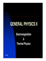
30
0
02.5
OUTPUT CURRENT vs.
RECEIVER OUTPUT LOW VOLTAGE
5
25
MAX481-01
OUTPUT LOW VOLTAGE (V)
OUTPUT CURRENT (mA)
1.5
15
10
0.5 1.0 2.0
20
35
40
45
0.9
0.1
-50 -25 25 75
RECEIVER OUTPUT LOW VOLTAGE vs.
TEMPERATURE
0.3
0.7
TEMPERATURE (°C)
OUTPUT LOW VOLTAGE (V)
050
0.5
0.8
0.2
0.6
0.4
0
100
125
MAX481-04
I
RO
= 8mA
-20
-4
1.5 2.0 3.0 5.0
OUTPUT CURRENT vs.
RECEIVER OUTPUT HIGH VOLTAGE
-8
-16
MAX481-02
OUTPUT HIGH VOLTAGE (V)
OUTPUT CURRENT (mA)
2.5 4.0
-12
-18
-6
-14
-10
-2
0
3.5 4.5
4.8
3.2
-50 -25 25 75
RECEIVER OUTPUT HIGH VOLTAGE vs.
TEMPERATURE
3.6
4.4
TEMPERATURE (°C)
OUTPUT HIGH VOLTAGE (V)
050
4.0
4.6
3.4
4.2
3.8
3.0
100
125
MAX481-03
I
RO
= 8mA
90
0
0 1.0 3.0 4.5
DRIVER OUTPUT CURRENT vs.
DIFFERENTIAL OUTPUT VOLTAGE
10
70
MAX481-05
DIFFERENTIAL OUTPUT VOLTAGE (V)
OUTPUT CURRENT (mA)
2.0 4.0
50
30
80
60
40
20
0.5 1.5 2.5 3.5
2.3
1.5
-50 -25 25 125
DRIVER DIFFERENTIAL OUTPUT VOLTAGE
vs. TEMPERATURE
1.7
2.1
MAX481-06
TEMPERATURE (°C)
DIFFERENTIAL OUTPUT VOLTAGE (V)
075
1.9
2.2
1.6
2.0
1.8
10050
2.4
R = 54
Ω
__________________________________________Typical Operating Characteristics
(V
CC
= 5V, T
A
= +25°C, unless otherwise noted.)
NOTES FOR ELECTRICAL/SWITCHING CHARACTERISTICS
Note 1: All currents into device pins are positive; all currents out of device pins are negative. All voltages are referenced to device
ground unless otherwise specified.
Note 2: All typical specifications are given for V
CC
= 5V and T
A
= +25°C.
Note 3: Supply current specification is valid for loaded transmitters when DE = 0V.
Note 4: Applies to peak current. See Typical Operating Characteristics.
Note 5: The MAX481/MAX483/MAX487 are put into shutdown by bringing RE high and DE low. If the inputs are in this state for less
than 50ns, the parts are guaranteed not to enter shutdown. If the inputs are in this state for at least 600ns, the parts are
guaranteed to have entered shutdown. See Low-Power Shutdown Mode section.
MAX481/MAX483/MAX485/MAX487–MAX491/MAX1487
Low-Power, Slew-Rate-Limited
RS-485/RS-422 Transceivers
6 _______________________________________________________________________________________
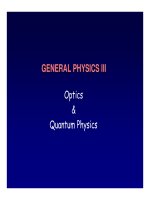
____________________________Typical Operating Characteristics (continued)
(V
CC
= 5V, T
A
= +25°C, unless otherwise noted.)
120
0
08
OUTPUT CURRENT vs.
DRIVER OUTPUT LOW VOLTAGE
20
100
MAX481-07
OUTPUT LOW VOLTAGE (V)
OUTPUT CURRENT (mA)
6
60
40
24
80
10
12
140
-120
0
-7 -5 -1 5
OUTPUT CURRENT vs.
DRIVER OUTPUT HIGH VOLTAGE
-20
-80
MAX481-08
OUTPUT HIGH VOLTAGE (V)
OUTPUT CURRENT (mA)
-3 1
-60
3
-6 -4 -2 0 2 4
-100
-40
100
-40-60 -20 40 100 120
MAX1487
SUPPLY CURRENT vs. TEMPERATURE
300
MAX481-13
TEMPERATURE (°C)
SUPPLY CURRENT (µA)
20 60 80
500
200
600
400
0
0
140
MAX1487; DE = V
CC
, RE = X
MAX1487; DE = 0V, RE = X
100
-50 -25 50 100
MAX481/MAX485/MAX490/MAX491
SUPPLY CURRENT vs. TEMPERATURE
300
MAX481-11
TEMPERATURE (°C)
SUPPLY CURRENT (µA)
25 75
500
200
600
400
0
0
125
MAX481/MAX485; DE = V
CC
, RE = X
MAX485; DE = 0, RE = X,
MAX481; DE = RE = 0
MAX490/MAX491; DE = RE = X
MAX481; DE = 0, RE = V
CC
100
-50 -25 50 100
MAX483/MAX487–MAX489
SUPPLY CURRENT vs. TEMPERATURE
300
MAX481-12
TEMPERATURE (°C)
SUPPLY CURRENT (µA)
25 75
500
200
600
400
0
0
125
MAX483; DE = V
CC
, RE = X
MAX487; DE = V
CC
, RE = X
MAX483/MAX487; DE = 0, RE = V
CC
MAX483/MAX487; DE = RE = 0,
MAX488/MAX489; DE = RE = X
MAX481/MAX483/MAX485/MAX487–MAX491/MAX1487
Low-Power, Slew-Rate-Limited
RS-485/RS-422 Transceivers
_______________________________________________________________________________________ 7
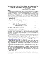
______________________________________________________________Pin Description
MAX481
MAX483
MAX485
MAX487
MAX1487
TOP VIEW
NOTE: PIN LABELS Y AND Z ON TIMING, TEST, AND WAVEFORM DIAGRAMS REFER TO PINS A AND B WHEN DE IS HIGH.
TYPICAL OPERATING CIRCUIT SHOWN WITH DIP/SO PACKAGE.
1
2
3
4
8
5
V
CC
GND
DI
DE
RE
RO
R
D
Rt
Rt
7
6
D
R
DE
RE
DI
RO
A
B
1
2
3
4
8
7
6
5
V
CC
B
A
GND
DI
DE
RE
RO
DIP/SO
R
D
1
2
3
4
8
7
6
5
V
CC
A
GND
DE
RE
B
RO
µMAX
B
A
DI
MAX481
MAX483
MAX485
MAX487
MAX1487
Figure 1. MAX481/MAX483/MAX485/MAX487/MAX1487 Pin Configuration and Typical Operating Circuit
µMAX
—
—
5
6
7
8
—
2
—
1
3
—
µMAX
4
5
6
7
—
—
8
—
1
—
2
—
DIP/SO DIP/SO
2 3
Receiver Output Enable. RO is enabled when RE is low; RO is
high impedance when RE is high.
3 4
Driver Output Enable. The driver outputs, Y and Z, are enabled
by bringing DE high. They are high impedance when DE is low. If
the driver outputs are enabled, the parts function as line drivers.
While they are high impedance, they function as line receivers if
RE is low.
DIP/SO
—
4 5
Driver Input. A low on DI forces output Y low and output Z high.
Similarly, a high on DI forces output Y high and output Z low.
5 6, 7 Ground
— 9 Noninverting Driver Output
— 10 Inverting Driver Output
—
3
4
6 — Noninverting Receiver Input and Noninverting Driver Output
— 12 Noninverting Receiver Input
5
6
—
8
RE
DE
DI
GND
Y
Z
A
A
7 — — B Inverting Receiver Input and Inverting Driver Output
— 7 11 B Inverting Receiver Input
8 1 14 V
CC
Positive Supply: 4.75V ≤ V
CC
≤ 5.25V
— — 1, 8, 13 N.C. No Connect—not internally connected
FUNCTION
NAME
431 2
Receiver Output: If A > B by 200mV, RO will be high;
If A < B by 200mV, RO will be low.
2 RO
PIN
FUNCTIONNAME
MAX481/MAX483/
MAX485/MAX487/
MAX1487
MAX488/
MAX490
MAX489/
MAX491
MAX481/MAX483/MAX485/MAX487–MAX491/MAX1487
__________Applications Information
The MAX481/MAX483/MAX485/MAX487–MAX491 and
MAX1487 are low-power transceivers for RS-485 and RS-
422 communications. The MAX481, MAX485, MAX490,
MAX491, and MAX1487 can transmit and receive at data
rates up to 2.5Mbps, while the MAX483, MAX487,
MAX488, and MAX489 are specified for data rates up to
250kbps. The MAX488–MAX491 are full-duplex trans-
ceivers while the MAX481, MAX483, MAX485, MAX487,
and MAX1487 are half-duplex. In addition, Driver Enable
(DE) and Receiver Enable (RE) pins are included on the
MAX481, MAX483, MAX485, MAX487, MAX489,
MAX491, and MAX1487. When disabled, the driver and
receiver outputs are high impedance.
MAX487/MAX1487:
128 Transceivers on the Bus
The 48kΩ,
1
/
4
-unit-load receiver input impedance of the
MAX487 and MAX1487 allows up to 128 transceivers
on a bus, compared to the 1-unit load (12kΩ input
impedance) of standard RS-485 drivers (32 trans-
ceivers maximum). Any combination of MAX487/
MAX1487 and other RS-485 transceivers with a total of
32 unit loads or less can be put on the bus. The
MAX481/MAX483/MAX485 and MAX488–MAX491 have
standard 12kΩ Receiver Input impedance.
Low-Power, Slew-Rate-Limited
RS-485/RS-422 Transceivers
8 _______________________________________________________________________________________
MAX488
MAX490
TOP VIEW
1
2
3
4
RO
DI
GND
8
7
6
5
A
B
Z
Y
V
CC
DIP/SO
R
D
Rt
Rt
V
CC
5
6
7
8
RO
DI
GND
4
GND
DI
RO
3
2
A
B
Y
Z
V
CC
DR
R
D
1
3
V
CC
4
RO
2
A
1
6
5
7
8
GND
DI
Y
Z
B
µMAX
MAX488
MAX490
NOTE: TYPICAL OPERATING CIRCUIT SHOWN WITH DIP/SO PACKAGE.
MAX489
MAX491
DIP/SO
TOP VIEW
Rt
Rt
DE V
CC
RE GND
V
CC
RE
GND DE
RO
DI
9
10
12
11
B
A
Z
Y
5
RO
NC
DI
2
1, 8, 13
3 6, 7
144
1
2
3
4
5
6
7
14
13
12
11
10
9
8
V
CC
N.C.
N.C.
A
B
Z
Y
N.C.
RO
RE
DE
DI
GND
GND
R
D
D
RD
R
Figure 2. MAX488/MAX490 Pin Configuration and Typical Operating Circuit
Figure 3. MAX489/MAX491 Pin Configuration and Typical Operating Circuit