Tài liệu Brushed DC Motor Fundamentals doc
Bạn đang xem bản rút gọn của tài liệu. Xem và tải ngay bản đầy đủ của tài liệu tại đây (212.44 KB, 10 trang )
2004 Microchip Technology Inc. DS00905A-page 1
AN905
INTRODUCTION
Brushed DC motors are widely used in applications
ranging from toys to push-button adjustable car seats.
Brushed DC (BDC) motors are inexpensive, easy to
drive, and are readily available in all sizes and shapes.
This application note will discuss how a BDC motor
works, how to drive a BDC motor, and how a drive
circuit can be interfaced to a PIC
®
microcontroller.
PRINCIPLES OF OPERATION
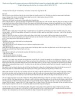
The construction of a simple BDC motor is shown in
Figure 1. All BDC motors are made of the same basic
components: a stator, rotor, brushes and a commutator.
The following paragraphs will explain each component
in greater detail.
Stator
The stator generates a stationary magnetic field that
surrounds the rotor. This field is generated by either
permanent magnets or electromagnetic windings. The
different types of BDC motors are distinguished by the
construction of the stator or the way the electromag-
netic windings are connected to the power source.
(See Types of Stepping Motors for the different BDC
motor types).
Rotor
The rotor, also called the armature, is made up of one
or more windings. When these windings are energized
they produce a magnetic field. The magnetic poles of
this rotor field will be attracted to the opposite poles
generated by the stator, causing the rotor to turn. As the
motor turns, the windings are constantly being
energized in a different sequence so that the magnetic
poles generated by the rotor do not overrun the poles
generated in the stator. This switching of the field in the
rotor windings is called commutation.
FIGURE 1: SIMPLE TWO-POLE BRUSHED DC MOTOR
Author: Reston Condit
Microchip Technology Inc.
N
Brushes
Commutator
Armature
Field
Magnet
SOUTH
NORTH
Axle
or Coil
Brushed DC Motor Fundamentals
AN905
DS00905A-page 2 2004 Microchip Technology Inc.
Brushes and Commutator
Unlike other electric motor types (i.e., brushless DC,
AC induction), BDC motors do not require a controller
to switch current in the motor windings. Instead, the
commutation of the windings of a BDC motor is done
mechanically. A segmented copper sleeve, called a
commutator, resides on the axle of a BDC motor. As the
motor turns, carbon brushes slide over the commutator,
coming in contact with different segments of the
commutator. The segments are attached to different
rotor windings, therefore, a dynamic magnetic field is
generated inside the motor when a voltage is applied
across the brushes of the motor. It is important to note
that the brushes and commutator are the parts of a
BDC motor that are most prone to wear because they
are sliding past each other.
TYPES OF STEPPING MOTORS
As mentioned earlier, the way the stationary magnetic
field is produced in the stator differentiates the various
types of BDC motors. This section will discuss the
different types of BDC motors and the advantages/
disadvantages of each.
Permanent Magnet
Permanent Magnet Brushed DC (PMDC) motors are
the most common BDC motors found in the world.
These motors use permanent magnets to produce the
stator field. PMDC motors are generally used in appli-
cations involving fractional horsepower because it is
more cost effective to use permanent magnets than
wound stators. The drawback of PMDC motors is that
the magnets lose their magnetic properties over time.
Some PMDC motors have windings built into them to
prevent this from happening. The performance curve
(voltage vs. speed), is very linear for PMDC motors.
Current draw also varies linearly with torque. These
motors respond to changes in voltage very quickly
because the stator field is always constant.
FIGURE 2: PERMANENT MAGNET DC
MOTORS
Shunt-Wound
Shunt-wound Brushed DC (SHWDC) motors have the
field coil in parallel (shunt) with the armature. The
current in the field coil and the armature are indepen-
dent of one another. As a result, these motors have
excellent speed control. SHWDC motors are typically
used applications that require five or more horsepower.
Loss of magnetism is not an issue in SHWDC motors
so they are generally more robust than PMDC motors.
FIGURE 3: SHUNT-WOUND DC
MOTORS
Series-Wound
Series-wound Brushed DC (SWDC) motors have the
field coil in series with the armature. These motors are
ideally suited for high-torque applications because the
current in both the stator and armature increases under
load. A drawback to SWDC motors is that they do not
have precise speed control like PMDC and SHWDC
motors have.
FIGURE 4: SERIES-WOUND DC
MOTORS
Armature
Brush
Permanent
Magnet Poles
DC
Voltage
Supply
Armature
Brush
Shunt
Field
DC
Voltage
Supply
Armature
Brush
Series
Field
DC
Voltage
Supply
2004 Microchip Technology Inc. DS00905A-page 3
AN905
Compound-Wound
Compound Wound (CWDC) motors are a combination
of shunt-wound and series-wound motors. As shown in
Figure 5, CWDC motors employ both a series and a
shunt field. The performance of a CWDC motor is a
combination of SWDC and SHWDC motors. CWDC
motors have higher torque than a SHWDC motor while
offering better speed control than SWDC motor.
FIGURE 5: COMPOUND-WOUND DC
MOTORS
BASIC DRIVE CIRCUITS
Drive circuits are used in applications where a control-
ler of some kind is being used and speed control is
required. The purpose of a drive circuit is to give the
controller a way to vary the current in the windings of
the BDC motor. The drive circuits discussed in this
section allow the controller to pulse width modulate the
voltage supplied to a BDC motor. In terms of power
consumption, this method of speed control is a far more
efficient way to vary the speed of a BDC motor
compared to traditional analog control methods.
Traditional analog control required the addition of an
inefficient variable resistance in series with the motor.
BDC motors are driven in a variety of ways. In some
cases the motor only needs to spin in one direction.
Figure 6 and Figure 7 show circuits for driving a BDC
motor in one direction. The first is a low-side drive and
the second is a high-side drive. The advantage to using
the low-side drive is that a FET driver is not typically
needed. A FET driver is used to:
1. bring the TTL signal driving a MOSFET to the
potential level of the supply voltage,
2. provide enough current to drive the MOSFET
(1)
,
3. and provide level shifting in half-bridge
applications.
Note that in each circuit there is a diode across the
motor. This diode is there to prevent Back Electromag-
netic Flux (BEMF) voltage from harming the MOSFET.
BEMF is generated when the motor is spinning. When
the MOSFET is turned off, the winding in the motor is
still charged at this point and will produce reverse
current flow. D1 must be rated appropriately so that it
will dissipate this current.
FIGURE 6: LOW-SIDE BDC MOTOR
DRIVE CIRCUIT
FIGURE 7: HIGH-SIDE BDC MOTOR
DRIVE CIRCUIT
Resistors R1 and R2 in Figure 6 and Figure 7 are
important to the operation of each circuit. R1 protects
the microcontroller from current spikes while R2
ensures that Q1 is turned off when the input pin is
tristated.
Note 1: The second point typically does not apply
to most PICmicro
®
microcontroller
applications because PIC microcontroller
I/O pins can source 20 mA.
Armature
Brush
Shunt
Field
DC
Voltage
Supply
Series
Field
V
CC
D1
BDC
Motor
R1
R2
To Controller
V
CC
V
CC
D1
BDC
Motor
R1
R2
To Controller
AN905
DS00905A-page 4 2004 Microchip Technology Inc.
Bidirectional control of a BDC motor requires a circuit
called an H-bridge. The H-bridge, named for it's
schematic appearance, is able to move current in either
direction through the motor winding. To understand
this, the H-bridge must be broken into its two sides, or
half-bridges. Referring to Figure 8, Q1 and Q2 make up
one half-bridge while Q3 and Q4 make up the other
half-bridge. Each of these half-bridges is able to switch
one side of the BDC motor to the potential of the supply
voltage or ground. When Q1 is turned on and Q2 is off,
for instance, the left side of the motor will be at the
potential of the supply voltage. Turning on Q4 and
leaving Q3 off will ground the opposite side of the
motor. The arrow labeled I
FWD
shows the resulting
current flow for this configuration.
Note the diodes across each of the MOSFETs (D1-D4).
These diodes protect the MOSFETs from current spikes
generated by BEMF when the MOSFETs are switched
off. These diodes are only needed if the internal
MOSFET diodes are not sufficient for dissipating the
BEMF current.
The capacitors (C1-C4) are optional. The value of
these capacitors is generally in the 10 pF range. The
purpose of these capacitors is to reduce the RF
radiation that is produced by the arching of the
commutators.
FIGURE 8: BIDIRECTION BDC MOTOR DRIVE (H-BRIDGE) CIRCUIT
The different drive modes for and H-bridge circuit are
shown in Table 1. In Forward mode and Reverse mode
one side of the bridge is held at ground potential and
the other side at V
SUPPLY
. In Figure 8 the I
FWD
and I
RVS
arrows illustrate the current paths during the Forward
and Reverse modes of operation. In Coast mode, the
ends of the motor winding are left floating and the
motor coasts to a stop. Brake mode is used to rapidly
stop the BDC motor. In Brake mode, the ends of the
motor are grounded. The motor behaves as a genera-
tor when it is rotating. Shorting the leads of the motor
acts as a load of infinite magnitude bringing the motor
to a rapid halt. The I
BRK
arrow illustrates this.
There is one very important consideration that must be
taken into account when designing an H-bridge circuit.
All MOSFETs must be biased to off when the inputs to
the circuit are unpredictable (like when the microcon-
troller is starting up). This will ensure that the
MOSFETs on each half-bridge of the H-bridge will
never be turned on at the same time. Turning
MOSFETs on that are located on the same half-bridge
will cause a short across the power supply, ultimately
damaging the MOSFETs and rendering the circuit
inoperable. Pull-down resistors at each of the MOSFET
driver inputs will accomplish this functionality (for the
configuration shown in Figure 8).
R1
R2
Q1
Q2
C1
C2
C3
C4
Q3
Q4
Motor
BDC
V
SUPPLY
R3
R4
CTRL1
CTRL2
CTRL3
CTRL4
D3
D4
D1
D2
I
RVS
I
BRK
I
FWD
TABLE 1: H-BRIDGE MODES OF
OPERATION
Q1
(CTRL1)
Q2
(CTRL2)
Q3
(CTRL3)
Q4
(CTRL4)
Forward on off off on
Reverse off on on off
Coast off off off off
Brake off on off on
2004 Microchip Technology Inc. DS00905A-page 5
AN905
SPEED CONTROL
The speed of a BDC motor is proportional to the voltage
applied to the motor. When using digital control, a
pulse-width modulated (PWM) signal is used to gener-
ate an average voltage. The motor winding acts as a
low pass filter so a PWM waveform of sufficient
frequency will generate a stable current in the motor
winding. The relation between average voltage, the
supply voltage, and duty cycle is given by:
EQUATION 1:
Speed and duty cycle are proportional to one another.
For example, if a BDC motor is rated to turn at 15000
RPM at 12V, the motor will (ideally) turn at 7500 RPM
when a 50% duty cycle waveform is applied across the
motor.
The frequency of the PWM waveform is an important
consideration. Too low a frequency will result in a noisy
motor at low speeds and sluggish response to changes
in duty cycle. Too high a frequency lessens the
efficiency of the system due to switching losses in the
switching devices. A good rule of thumb is to modulate
the input waveform at a frequency in the range of 4 kHz
to 20 kHz. This range is high enough that audible motor
noise is attenuated and the switching losses present in
the MOSFETs (or BJTs) are negligible. Generally, it is a
good idea to experiment with the PWM frequency for a
given motor to find a satisfactory frequency.
So how can a PIC microcontroller be used to generate
the PWM waveform required to control the speed of a
BDC motor? One way would be to toggle an output pin
by writing assembly or C code dedicated to driving that
pin
(1)
. Another way is to select a PIC microcontroller
with a hardware PWM module. The modules available
from Microchip for this purpose are the CCP an ECCP
modules. Many of the PIC microcontrollers have CCP
and ECCP modules. Refer to the product selector
guide to find the devices having these features.
The CCP module (short for Capture Compare and
PWM) is capable of outputting a 10-bit resolution PWM
waveform on a single I/O pin. 10-bit resolution means
that 2
10
, or 1024, possible duty cycle values ranging
from 0% to 100% are achievable by the module. The
advantage to using this module is that it automatically
generates a PWM signal on an I/O pin which frees up
processor time for doing other things. The CCP module
only requires that the developer configure the parame-
ters of the module. Configuring the module includes
setting the frequency and duty cycle registers.
The ECCP module (short for Enhanced Capture
Compare and PWM) provides the same functionality as
the CCP module with the added capability of driving a
full or half-bridge circuit. The ECCP module also has
auto-shutdown capability and programmable dead
band delay.
FEEDBACK MECHANISMS
Though the speed of a BDC motor is generally propor-
tional to duty cycle, no motor is ideal. Heat, commutator
wear and load all affect the speed of a motor. In
systems where precise speed control is required, it is a
good idea to include some sort of feedback mechanism
in the system.
Speed feedback is implemented in one of two ways.
The first involves the use of a speed sensor of some
kind. The second uses the BEMF voltage generated by
the motor.
Sensored Feedback
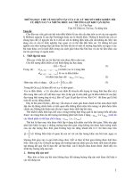
There are a variety of sensors used for speed feed-
back. The most common are optical encoders and hall
effect sensors. Optical encoders are made up of
several components. A slotted wheel is mounted to the
shaft at the non-driving end of the motor. An infrared
LED provides a light source on one side of the wheel
and a photo transistor detects light on the other side of
the wheel (see Figure 9). Light passing through the
slots in the wheel will turn the photo transistor on. As
the shaft turns, the photo transistor turns on and off with
the passing of the slots in the wheel. The frequency at
which the transistor toggles is an indication of motor
speed. In the case of positioning applications, an
optical encoder will also provide feedback as to the
position of the motor.
FIGURE 9: OPTICAL ENCODER
Note 1: Microchip Application Note AN847
provides an assembly code routine for
pulse-width modulating an I/O pin in
firmware.
V
AVERAGE
= D
×
V
SUPPLY
Note: Microchip Application Note AN893 gives a
detailed explanation of configuring the
ECCP module for driving a BDC motor.
The application note also includes
firmware and drive circuit examples.
Photo Transistor
IR LED
slotted
wheel
Front View Side View