Tài liệu Brake02 docx
Bạn đang xem bản rút gọn của tài liệu. Xem và tải ngay bản đầy đủ của tài liệu tại đây (312.23 KB, 11 trang )
10 LEXUS Technical Training
1. Explain the difference between conventional and diagonal split
piping system and their application.
2. Describe the function of the compensating port of the master
cylinder.
3. Explain the operation of the residual check valve on the drum
brake circuit of the master cylinder.
4. Explain the safety advantage of having two hydraulic circuits in
the master cylinder.
5. Describe the difference between the Portless and Lockheed master
cylinders.
Section 2
MASTER CYLINDER
Lesson Objectives
Master Cylinder
The master cylinder converts the motion of the brake pedal into hydraulic
pressure. It consists of the reservoir tank, which contains the brake fluid;
and the piston and cylinder which generate the hydraulic pressure.
The reservoir tank is made mainly of synthetic resin, while the
cylinders are made of cast iron or an aluminum alloy.
Master Cylinder
Stores brake fluid and
converts the motion of
the brake pedal into
hydraulic pressure.
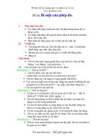
The tandem master cylinder has two separate hydraulic chambers.
This creates in effect two separate hydraulic braking circuits. If one of
these circuits becomes inoperative, the other circuit can still function to
stop the vehicle. Stopping distance is increased significantly, however,
when operating on only one braking circuit. This is one of the vehicles’
most important safety features.
On front−engine rear−wheel−drive vehicles, one of the chambers
provides hydraulic pressure for the front brakes while the other
provides pressure for the rear.
Master Cylinder
Tandem Master
Cylinder
Conventional
Piping
Section 2
12 LEXUS Technical Training
Conventional Piping
for Front Engine
Rear Drive
When one circuit fails the
other remains intact to
stop the vehicle.
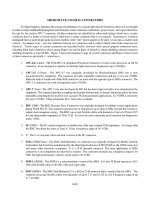
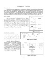
On front−engine front−wheel−drive vehicles, however, extra braking load
is shifted to the front brakes due to reduced weight in the rear. To
compensate for hydraulic failure in the front brake circuit with the
lighter rear axle weight, a diagonal brake line system is used. This
consists of one brake system for the right front and left rear wheels,
and a separate system for the left front and right rear wheels. Braking
efficiency remains equal on both sides of the vehicle (but with only half
the normal braking power) even if one of the two separate systems
should have a problem.
Diagonal Piping for
Front Engine
Front Drive
Improves braking efficiency
if one circuit fails by having
one front wheel and one
rear wheel braking.
Diagonal Split Piping
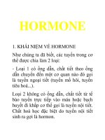
Master Cylinder
The Master Cylinder has a single bore separated into two separate
chambers by the Primary and Secondary Pistons. On the front of the
master cylinder Primary Piston is a rubber Piston Cup, which seals the
Primary Circuit of the cylinder. Another Piston Cup is also fitted at the
rear of the Primary Piston to prevent the brake fluid from leaking out
of the rear of the cylinder.
At the front of the Secondary Piston is a Piston Cup which seals the
Secondary Circuit. At the rear of the Secondary Piston the other Piston
Cup seals the Secondary Cylinder from the Primary Cylinder. The
Primary Piston is linked to the brake pedal via a pushrod.
Master Cylinder
Components
The Master Cylinder has a
single bore separated into
two separate chambers
by the Primary and
Secondary Pistons.
When the brakes are not applied, the piston cups of the Primary and
Secondary Pistons are positioned between the Inlet Port and the
Compensating Port. This provides a passage between the cylinder and
the reservoir tank.
The Secondary Piston is pushed to the right by the force of Secondary
Return Spring, but prevented from going any further by a stopper bolt.
When the brake pedal is depressed, the Primary Piston moves to the
left. The piston cup seals the Compensating Port blocking the passage
between the Primary Pressure Chamber and the Reservoir Tank. As
the piston is pushed farther, it builds hydraulic pressure inside the
cylinder and is applied or transmitted to the wheel cylinders in that
circuit. The same hydraulic pressure is also applied to the Secondary
Construction
Normal Operation
Section 2
14 LEXUS Technical Training
Piston. Hydraulic pressure in the Primary Chamber moves the
Secondary Piston to the left also. After the Compensating Port of the
Secondary Chamber is closed, fluid pressure builds and is transmitted
to the secondary circuit.
Brake Application
As the piston cup
passes the compensating
Port pressure begins
to increase in the
hydraulic circuit.
When the brake pedal is released, the pistons are returned to their
original position by hydraulic pressure and the force of the return
springs. However, because the brake fluid does not return to the
master cylinder immediately, the hydraulic pressure inside the cylinder
drops momentarily. As a result, the brake fluid inside the reservoir
tank flows into the cylinder via the inlet port, through small holes
provided at the front of the piston, and around the piston cup. This
design prevents vacuum from developing and allowing air to enter at
the wheel cylinders.
Brake Release
Brake fluid inside the
reservoir tank flows into the
cylinder via the inlet port,
through small holes
provided at the front of the
piston, and around the
piston cup.