Tài liệu Automatic Transmissions P12 ppt
Bạn đang xem bản rút gọn của tài liệu. Xem và tải ngay bản đầy đủ của tài liệu tại đây (147.55 KB, 11 trang )
182 TOYOTA Technical Training
1 Describe the control of the key lock mechanism for the mechanical
shift lock system.
2. Describe the control of the shift lock mechanism for the mechanical
shift lock systems.
3. Describe the effect of the brake pedal input on the shift lock
mechanism for electrical and electrical/mechanical systems.
4. Describe the effect of the gear shift selector position on the key lock
mechanism for electrical systems.
5. Given a voltmeter and repair manual, demonstrate the pin checks of
the shift position switch.
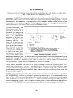
Section 12
SHIFT LOCK SYSTEM
Lesson Objectives:
SHIFT LOCK SYSTEM
Automatic Transmissions - Course 262 183
The shift lock system is designed to ensure the proper operation of the
automatic transmission. The driver must depress the brake pedal in
order to move the gear selector from Park to any other range. In
addition, the ignition key cannot be turned to the Lock position and
removed from the ignition switch unless the gear selector is placed in
the Park position.
There are three systems available in Toyota models; electrical,
electrical/ mechanical and mechanical. We will not cover the
application by model but rather by system type. For the specifics on a
particular model, consult the repair manual.
Shift Lock Systems
Section 12
184 TOYOTA Technical Training
The electrical type uses electrical control of the shift lock mechanism,
as well as the key lock mechanism.
The shift lock mechanism is made up of a number of components as
seen in the illustration below.
Shift Lock
Mechanism
The shift position switch (shift lock control switch) is used to detect the
position of the shift lever. It has two contacts, PI and P2. When the
select lever is in the Park position, PI is on (closed) and P2 is off (open).
In this position, the key can be removed but the select lever is locked in
position.
When the select lever is in a position other than Park, PI is off (open)
and P2 is on (closed). In this position, the key cannot be removed.
The grooved pin is part of the normal detent mechanism which
requires that the shift lever button be depressed in order to move the
gear selector into and out of Park position and also into Manual 2 or
Manual Low positions. The shift lock plate is mounted next to the
detent plate. In the Park position, the grooved pin fits into the slot at
the top of the shift plate. The shift lock plate movement is limited by
the plate stopper when the solenoid is not energized.
Electrical Shift
Lock Type
Shift Lock
Mechanism
SHIFT LOCK SYSTEM
Automatic Transmissions - Course 262 185
Shift Lock
Mechanism
Operation
The shift lock plate is
blocked by the shift lock
solenoid and plate stopper
holding the shift lever in teh
park position until
energized.
In order to move the shift lever out of Park, the ignition switch must be
in the Accessory or ON position and the brake pedal must be
depressed. When the brake pedal is depressed, the ECU turns on the
solenoid, moving the plate stopper and allowing the shift lock plate to
move down with the grooved pin.
If the shift lock solenoid becomes inoperative, the shift lever cannot be
moved and the vehicle cannot be moved. The shift lock override button
can be used to release the plate stopper from the shift lock plate,
releasing the shift lever so it can be moved from the Park position.
The ECU is generally found near the shift select lever. The shift lock
system computer controls operation of the key lock solenoid and the
shift lock solenoid based on signals from the shift position switch and
the stop light switch.
Shift Lock Override
Button
Shift Lock ECU
Section 12
186 TOYOTA Technical Training
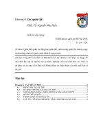
A camshaft is provided at the end of the key cylinder rotor. This
camshaft has a cam with the cut−out portion of its stroke from the ACC
position to the ON or Start position. The pin of the key lock solenoid
protrudes out against the cam when the current is on and is pulled
back by the return spring when the current is off.
When the shift lever is shifted to a range other than the P range,
current flows from the computer to the key lock solenoid, causing the
pin to protrude out. If the key cylinder is turned with the pin in this
position, it can be turned to the ACC position but cannot be turned
further, due to the pin pushing against the cam. This prevents the key
cylinder from being turned to the Lock position.
The current to the key lock solenoid is cut off when the shift lever is
shifted to the P range and the pin is pulled back by the return spring.
This allows the key cylinder to be turned to the Lock position, and the
key can be removed.
The shift lock system computer controls operation of the key lock
solenoid and the shift lock solenoid based on signals from the shift
position switch and the stop light switch.
The shift position switch P2 is on (closed) when the shift lever is in a
range other than the Park range. Current from the ACC and ON
terminals of the ignition switch flows to Tr2 through the timer circuit.
The base circuit of Tr2 is grounded by switch P2, and Tr2 goes on,
energizing the key lock solenoid, preventing the key from going to the
Lock position. The timer circuit cuts off the flow of current to Tr2
approximately one hour after the ignition switch is turned from ON to
ACC, switching off the key lock solenoid. The timer circuit prevents the
battery from being discharged.
By placing the gear selector in the Park position, switch P2 is off
(open), current no longer flows to the base of Tr2 and it goes off. The
solenoid is no longer energized, and the solenoid plunger is retracted,
and the key can be removed.
Key Interlock
System
Shift Lock System
Computer
Key Lock Solenoid
Control