Tài liệu Automatic Transmissions P3 pdf
Bạn đang xem bản rút gọn của tài liệu. Xem và tải ngay bản đầy đủ của tài liệu tại đây (329.01 KB, 25 trang )
Automatic Transmissions - Course 262
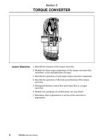
1. Manipulate transmission components to demonstrate power flow
through a simple planetary gear set for:
• Gear reduction
• Gear increase (overdrive)
• Reverse
2. Identify the three major components of the simple planetary gear set.
3. Describe the function of the simple planetary gear set to provide:
• Rotational speed change
• Rotational torque change
• Change in rotational direction
4. Demonstrate the measurement for wear on planetary carrier assembly
and determine serviceability.
5. Describe the operation of the following holding devices:
• Multiplate clutch
• Brake band
• One-way clutch
Section 3
SIMPSON PLANETARY GEAR UNIT
Lesson Objectives
SECTION 3
22 TOYOTA Technical Training
Toyota automatic transmissions use the Simpson−type planetary gear
unit. This unit is made up of two simple planetary gear sets arranged
on the same axis with a common sun gear. These gear sets are called
the front planetary gear set and the rear planetary gear set, based on
their position in the transmission. These two planetary gear sets result
in a three−speed automatic transmission having three forward gears
and one reverse gear.
Simpson Planetary
Gear Set
Made up of two
simple planetary gear
sets arranged on the
same axis with a
common sun gear.
These planetary gear sets, the brakes and clutches that control their
rotation, and the bearings and shafts for torque transmission are called
the planetary gear unit.
The planetary gear unit is used to increase or decrease engine torque,
increase or decrease vehicle speed, reverse direction of rotation or
provide direct drive. It is basically a lever that allows the engine to
move heavy loads with less effort.
There is an inverse relationship which exists between torque and speed.
For example: when a vehicle is stopped it requires a great deal of torque
to get it to move. A low gear is selected which provides high torque at
low vehicle speed. As the heavy load begins to move, less leverage is
required to keep it in motion. As the load remains in motion and speed
increases, torque requirements are low. With a suitable number of levers
or torque ratios, improved performance and economy are possible.
Before getting into simple planetary gears, it is necessary to
understand gear rotation and gear ratios or leverage. When two
Gear Rotational
Direction and
Gear Ratio
SIMPSON PLANETARY GEAR UNIT
Automatic Transmissions - Course 262
external gears are in mesh as illustrated below, they will rotate in
opposite directions. That is, when the small gear is rotated in a
clockwise direction, it will cause the larger gear to rotate in a
counter−clockwise direction. This is important to obtain a change in
output direction, such as in reverse.
Gear Rotational Di-
rection
When two external
gears are in mesh,
they will rotate in
opposite directions.
The gear ratio that these two gears provide will be a lever advantage.
The rotating speed of an output gear is determined by the number of
teeth of each gear. The gear ratio, and thus the rotational speed of the
output gear, can be found by dividing the number of output gear teeth
by the number of input gear teeth. These gear ratios are determined by
the engineers and fixed in the manufacture of the transmission.
Gear ratio
Number of output gear teeth
Gear ratio =
Number of input gear teeth
Gear ratio
24
1 6:1Gear ratio =
15
= 1.6:1
In the illustration above, if the input gear has 15 teeth and the output
gear has 24 teeth, the gear ratio is 1.6 to 1 (1.6:1). In other words, the
input gear has to turn slightly more than one and one−half turns to
have the output gear turn once. The output gear would turn slower
than the input gear which would be a speed decrease. The advantage in
this example is an increase in torque capability.
SECTION 3
24 TOYOTA Technical Training
To contrast this illustration, let’s assume that a set of gears have the
same diameter with the same number of teeth. If we determine the
gear ratio using the formula above, the ratio is 1 to 1 (1:1). In this
example there is no leverage or speed increase. One rotation of the
input gear results in one rotation of the output gear and there is no
lever advantage.
When an external gear is in mesh with an internal gear as illustrated
below, they will rotate in the same direction. This is necessary to get a
change in output gear ratio. The gear ratio here can be determined in
the same manner as was just discussed. Since the ratio is only
accomplished when all members of the planetary gear set function
together, we’ll examine gear ratios of the planetary gear set under the
Simple Planetary Gear Set.
Gear Rotational Di-
rection
When an external
gear is in mesh with
an internal gear,
they will rotate in
the same direction.
SIMPSON PLANETARY GEAR UNIT
Automatic Transmissions - Course 262
Our introduction to Toyota automatic transmissions will begin with a
simple planetary gear set. A planetary gear set is a series of three
interconnecting gears consisting of a sun gear, several pinion gears,
and a ring gear. Each pinion gear is mounted to a carrier assembly by a
pinion shaft. The sun gear is located in the center of the assembly;
several pinion gears rotate around the sun gear; and a ring gear
surrounds the pinion gears. This gear assembly is called the
planetary" gears because the pinion gears resemble planets revolving
around the sun.
In a planetary gear design, we are able to get different gear ratios
forward and reverse, even though the gear shafts are located on the
same axis.
Simple Planetary
Gear Operation
Carrier
Ring gear
Sun gear
Sun gear
Carrier
Ring gear
Ring gear
Carrier
Sun gear
HELD
POWER
INPUT
Sun gear
Ring gear
Ring gear
Carrier
Sun gear
Carrier
POWER
OUTPUT
ROTATIONAL
SPEED TORQUE
ROTATIONAL
DIRECTION
Gear ratios can also be determined in a planetary gear set although it
is not something that can easily be changed. The gear ratio of the
planetary gear set is determined by the number of teeth of the carrier,
ring gear, and sun gear. Since the carrier assembly has no teeth and
the pinion gears always operate as idle gears, their number of teeth is
not related to the gear ratio of the planetary gear set. However, an
arbitrary number needs to be assigned to the carrier in order to
calculate the ratio. Simply count the number of teeth on the sun gear
and the ring gear. Add these two numbers together and you have the
carrier gear number for calculation purposes.
Simple
Planetary
Gear Set
Planetary
Gear Ratios
SECTION 3
26 TOYOTA Technical Training
The number of carrier teeth (Zc) can be obtained by the following
equation:
Zc = Zr + Zs
where
Zc = Number of carrier teeth
Zr = Number of ring gear teeth
Zs = Number of sun gear teeth
For example, assume the number of ring gear teeth (Zr) to be 56 and
that of sun gear (Zs) to be 24. When the sun gear is fixed and the ring
gear operates as the input member, the gear ratio of the planetary gear
set is calculated as follows:
Gear ratio
Number of output gear teeth
Gear ratio =
Number of input gear teeth
Number of carrier teeth (Zc)
=
Number of ring gear teeth (Zr)
= 56 + 24 80
56
=
56
= 1.429
In other words, the input member would have to turn almost one and a
half times to one turn of the output member.
Now let’s assume that the carrier is the input member and the ring
gear is the output member. We would use the same equation in
determining the gear ratio.
Gear Ratio
56 56
Gear Ratio =
56 + 24
=
80
= 0.7
In this case, the input member would only turn a little more than a
half turn for the output member to turn once.
SIMPSON PLANETARY GEAR UNIT
Automatic Transmissions - Course 262
The operation of a simple planetary gear set is summarized in the
chart below: different speeds and rotational directions can be obtained
by holding one of the planetary members in a fixed position providing
input torque to another member, with the third member used as an
output member.
This chart represents more ratios and combinations than are used in
Toyota automatics, but are represented here to show the scope of its
design. The shaded areas represent the combinations used in Toyota
transmissions and are, therefore, the only combinations we will
discuss.
HELD
POWER POWER
ROTATIONAL
ROTATIONAL
HELD
POWER
INPUT
POWER
OUTPUT
SPEED TORQUE
ROTATIONAL
DIRECTION
Ring gear
Sun gear Carrier Reduced Increased
Same
direction as
Ring gear
Carrier Sun gear Increased Reduced
direction as
drive member
S n gear
Ring gear Carrier Reduced Increased
Same
direction as
Sun gear
Carrier Ring gear Increased Reduced
direction as
drive member
Carrier
Sun gear Ring gear Reduced Increased
Opposite
direction as
Carrier
Ring gear Sun gear Increased Reduced
direction as
drive member
Operation
Simple Planetary
Gear Operation
SECTION 3
28 TOYOTA Technical Training
When the ring gear or sun gear is held in a fixed position, and either of
the other members is an input member, the output gear rotational
direction is always the same as the input gear rotational direction.
When the internal teeth of the ring gear turns clockwise, the external
teeth of the pinion gears walk around the fixed sun gear while rotating
clockwise. This causes the carrier to rotate at a reduced speed.
Reduction
Example: Speed
reduction -
torque increase
Sun gear - Held member
(15 teeth)
Ring gear - Input member
(45 teeth)
Carrier - Output member
(45 + 15 teeth)
The gear ratio is computed as follows:
Gear ratio =
Number of output gear teeth
Gear ratio =
Number of input gear teeth
Gear ratio
45 + 15
1 3:1Gear ratio =
45
= 1.3:1
In this example, the input gear (ring gear) must turn 1.3 times to 1
rotation of the output gear (carrier). This example is used in second
gear.
Forward Direction
SIMPSON PLANETARY GEAR UNIT
Automatic Transmissions - Course 262
When the carrier turns clockwise, the external toothed pinion gears
walk around the external toothed sun gear while rotating clockwise.
The pinion gears cause the internal toothed ring gear to accelerate to a
speed greater than the carrier speed in a clockwise direction.
Overdrive
Example: Speed
increase -
torque reduction
Sun gear - Held member
(15 teeth)
Carrier - Input member
(45 + 15 teeth)
Ring Gear - Output member
(45 teeth)
The gear ratio is computed as follows:
Gear ratio
45
75:1Gear ratio =
45 + 15
= .75:1
In this example, the input gear (carrier) must turn three−quarters of a
turn (.75) to 1 rotation of the output gear (ring gear). This example is
used in overdrive.
SECTION 3
30 TOYOTA Technical Training
Whenever the carrier is held and either of the other gears are input
members, the output gear will rotate in the opposite direction.
With the carrier held, when the external toothed sun gear turns
clockwise, the external toothed pinion gears on the carrier idle in place
and drive the internal toothed ring gear in the opposite direction.
Reverse
Example: Speed
reduction -
torque increase
Carrier - Held member
(45 + 75 teeth)
Sun gear - Input member
(15 teeth)
Ring gear - Output member
(45 teeth)
The gear ratio is computed as follows:
Gear ratio
45
3:1Gear ratio =
15
= 3:1
In this example, the input gear (sun) must turn three (3) times to 1
rotation of the output gear (ring gear). This example is used in first
gear and reverse gear.
When any two members are held together and another member
provides the input turning force, the entire assembly turns at the same
speed as the input member.
Now the gear ratios from a single planetary set do not give us the
desired ratios which take advantage of the optimum torque curve of the
engine. So it is necessary to use two single planetary gear sets which
share a common sun gear. This design is basic to most all automatic
transmissions in production today.
Reverse Direction
Direct Drive -
(One-To-One Ratio)