Tài liệu Basic Networking Technologies docx
Bạn đang xem bản rút gọn của tài liệu. Xem và tải ngay bản đầy đủ của tài liệu tại đây (512.16 KB, 36 trang )
1
○○○○○○○○○○○○○○○○○○○○○○○○○○○○○○○○○○○○○○○○○○○○○○○○
4
Basic Networking
Technologies
Terms you’ll need to understand:
✓ Media Access Control (MAC)
addressing
✓ Ethernet 802.3
✓ Ethernet_II
✓ Fast Ethernet
✓ Gigabit Ethernet
✓ Token Ring 802.5
✓ Fiber Distributed Data Interface
(FDDI)
✓ Copper Distributed Data Interface
(CDDI)
✓ Carrier Sense Multiple Access with
Collision Detect (CSMA/CD)
✓ Beaconing
✓ Ring insertion
✓ Ring monitor
✓ Dual homing
✓ H.323
✓ Signaling System 7 (SS7)
✓ Realtime Transport Protocol (RTP)
✓ RTP Control Protocol (RTCP)
✓ Quality Of Service (QOS)
Techniques you’ll need to master:
✓ Describing layer 2 MAC addresses
✓ Working with Ethernet, Token
Ring, and FDDI characteristics and
limitations
✓ Understanding basic multiservice
theory
2
○○○○○○○○○○○○○○○○○○○○○○○○○○○○○○○○○○○○○○○○
Chapter 4
This chapter concentrates on the characteristics and limitations of the different
types of Ethernet, Token Ring, and Fiber Distributed Data Interface (FDDI)
technologies. After reviewing each of these technologies, the chapter briefly turns
to voice and video communications that can be delivered over existing data net-
works. These topics are called Multiservice Services by Cisco.
The following CCIE blueprint objectives as determined by the Cisco Systems
CCIE program are covered in this chapter:
➤ Data Link layer—MAC addressing and IEEE 802.2 standards
➤ Ethernet/Fast Ethernet/Gigabit Ethernet—Encapsulation, Carrier Sense Mul-
tiple Access with Collision Detect (CSMA/CD), topology, speed, controller
errors, limitations, and the IEEE 802.3 standards
➤ Token Ring—Token passing, beaconing, active monitor, ring insertion, soft and
hard errors, topology, maximum transmission unit (MTU), speed, limitations
➤ FDDI/CDDI—Dual ring, encapsulation, class, redundancy, dual homing,
medium (including copper and fiber), claims, station management (SMT),
limitations
➤ Voice/Video—H.323, codecs, Signaling System 7 (SS7), Realtime Transport
Protocol (RTP), RTP Control Protocol (RTCP), Quality Of Service (QOS)
Additional information is provided for completeness and in preparation for addi-
tional subjects as the CCIE program expands. We will begin by discussing what
makes up a MAC address.
MAC Addressing
All devices that operate over a physical LAN medium require a unique address,
called the Media Access Control (MAC) address. The MAC address is also some-
times referred to as the physical address, burned-in address (BIA), or hardware
address. A MAC address is assigned to each hardware device that connects to a
LAN, such as an Ethernet NIC. In Token Ring networks, the MAC address can
be set in software.
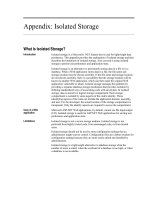
In IEEE 802 networks, the Data Link Control (DLC) layer of the OSI reference
model is divided into two sublayers: the Logical Link Control (LLC) layer and
the Media Access Control (MAC) layer. Figure 4.1 displays the location of the
LLC sublayer and the MAC sublayer in relation to the OSI model.
LLC Sublayer Functions
The LLC sublayer provides networks with connection or connectionless
enviroments. The LLC sublayer simply sits on top of all 802.x protocols and
provides a service to the Network layer.
3
○○○○○○○○○○○○○○○○○○○○○○○○○○○○○○○○○○○○○○○○
Basic Networking Technologies
Using IP as an example, we know that IP is a connectionless service, but the role
of the LLC sublayer is to identify that an IP packet is carried in the data portion
of the frame. The IP software then looks further into the frame to locate the
header information and the IP address.
MAC Sublayer Functions
The MAC sublayer simply provides access to the Physical layer, whether Ethernet
or any other medium is in use. To allow this communcaition each device must
have a unique address.
To enable all devices to have a unique address or MAC address, the network
interface cards have a unique MAC address located in Read Only Memory
(ROM). This unique address allows communication between devices regardless
of the physical medium. Let’s now describe the format of the MAC address.
MAC addresses are 48 bits long, and they are expressed primarily in two formats:
➤ 0060.7015.5e4d
➤ 00-60-70-15-5e-d4
The first byte, or octet, of a MAC address also contains two reserved bits that are
used to identify what destination device or devices are intended to be the recipent
of the frame:
➤ I/G—Individual/Group
➤ L/G—Local/Global
Layer 2 frames can be directed to one (I bit) or more devices (G bit). The Local/
Global bit defines whther the address is the burned in address or a locally as-
signed address.
OSI Model IEEE 802 Network
Network
Data Link
Physical
Logical Link Control
Media Access Control
Figure 4.1 IEEE 802 DLC.
4
○○○○○○○○○○○○○○○○○○○○○○○○○○○○○○○○○○○○○○○○
Chapter 4
Canonical vs. Non-Canonical
The IEEE refers to MAC addresses as Universal Addresses. The IEEE also specified
that when the bits are sent across the Ethernet Physical layer the least significant
bit is transmitted first. This is referred to as
non-canonical
. Token Ring is canonical,
which means that the most significant bit is transmiited first. Let’s look at a simple
example of sending the number 1 (decimal) across an Ethernet network. The num-
ber 1 in binary is 00000001. The non-canonical format of this is 10000000. This
means that on the Ethernet wire the bits 10000000 will be reversed by the receiving
device back to 00000001.
The majority of modern networks use a 48-bit addressing scheme or plan. MAC
addresses are represented using the hexadecimal numbering system. The first 24
bits represent the manufacturer’s identification, vendor’s code, or the organiza-
tion unique identifier (OUI). The next 24 bits typically provide a serial number
assigned by the vendor. To illustrate, here is an example of a Cisco MAC address:
006070-155e4d
In the preceding address, 00-60-70 (24 bits) identifies Cisco as the manufacturer
or vendor code, and 15-5e-4d (24 bits) identifies the serial number assigned by
Cisco. Manufacturers such as Cisco may have more than one OUI. For instance,
Cisco Systems has more than 20 OUIs from the IEEE.
Frames sent to MAC addresses can be classified as being sent to either unicast,
multicast, or broadcast addresses:
➤ Unicast Frame—A frame destined for a specific device. In the destination
address, a unicast frame will appear as 0xxxxxxx in the first byte.
➤ Multicast Address—A special address reserved for communication among a
group of devices. For example, 1xxxxxxx in the first byte.
➤ Broadcast Address—An address destined for all devices on the wire. For ex-
ample, FF-FF-FF-FF-FF-FF in the destination field indicates all devices
must read the frame.
Note that all frames will have their source MAC address as a single node (unicast).
Ethernet, Fast Ethernet, and
Gigabit Ethernet
Ethernet is one of the most popular local area network (LAN) technologies used
today. Ethernet can operate at three speeds:
5
○○○○○○○○○○○○○○○○○○○○○○○○○○○○○○○○○○○○○○○○
Basic Networking Technologies
➤ Ethernet—Allows transmission speeds of 10Mbps
➤ Fast Ethernet—Allows transmission speeds of 100Mbps
➤ Gigabit Ethernet—Allows transmission speeds of 1,000Mbps
10 Gigabit Ethernet is coming soon. The networking industry has formed
a coalition to make 10G a reality.
Originally, Ethernet started when the Xerox Corporation released a method of
allowing devices to share a common medium and communicate together. Table 4.1
shows a summary of Ethernet’s recent evolution.
In this section, we’ll review the three main Ethernet types, starting with a discus-
sion about traditional Ethernet.
Ethernet 802.3 and Ethernet_II
Ethernet has two versions available—Ethernet 802.3 and Ethernet_II. The main
difference between Ethernet 802.3 and Ethernet_II can be found within the
frame formats, as discussed later in this section. Original Ethernet and then the
second version called Ethernet_II was jointly developed by the Digital Equip-
ment Corporation, Intel, and Xerox Corporation, also know as the DIX Consor-
tium. Ethernet 802.3 is the standard defined by the IEEE.
The Ethernet specifications also define the frame sizes as follows:
➤ Minimum Ethernet Frame Size—64 bytes
➤ Maximum Ethernet Frame Size—1,514 bytes
Table 4.1 Ethernet history.
Date Timeline Event
1972 Work begins on Ethernet by Xerox
1980 Ethernet released
1982 Version II released by DIX (Digital, Intel, and Xerox)
1985 IEEE 802.3 Ethernet Standard is released
1994 Transmission of Ethernet over twisted pair wiring is released
1995 Fast Ethernet
1998 Gigabit Ethernet
6
○○○○○○○○○○○○○○○○○○○○○○○○○○○○○○○○○○○○○○○○
Chapter 4
When running IP, Ethernet_II is the default transmission method for
Cisco Routers.
Both Ethernet 802.3 and Ethernet_II are shared physical media technologies.
This means that when an end device on an Ethernet network needs to send data,
it first must wait to see if the physical medium is not being used before transmis-
sion can commence. The end device will listen to the wire using its ability to
carrier sense, which is part of the CSMA/CD. (CS stands for carrier sense.)
Further, while the data is transmitting, the end device must ensure no other de-
vice has transmitted at the same time on its receive interface. The sending station
will also listen to see if received data is different from the transmitted data. If it is
different, a collision occurred. Specifically, the end device is listening for a change
in voltage on the wire.
When a collision occurs, the sending end device transmits a jam signal (a random
signal used to inform all devices that a collision has been detected) and backs off
for a random value calculated with the back off algorithm. This method is called
Collision Sense Multiple Access with Collision Detection (CSMA/CD). As a result
of Ethernet’s shared-medium properties, Ethernet is sometimes referred to as
undeterministic. This is because end devices don’t know when they can send data
(that is, when the wire is clear), and end devices aren’t aware that another device
will transmit at the same time. A deterministic device is able to calculate the
maximum time that will pass before any end station will be able to transmit.
What is half-duplex and full duplex Ethernet? Half duplex Ethernet al-
lows only one device to send data or receive data at a time. Full duplex
Ethernet allows the capability of simultaneous data transmission be-
tween two devices. Full duplex Ethernet allows for better use of the
available bandwidth because both devices can send and receive data
at the same time.
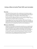
To illustrate CSMA/CD in action, Figure 4.2 shows an Ethernet network with
four PCs (end devices) trying to communicate. The following occurs:
1. PC-1 listens and determines that no one else is sending data.
2. PC-1 starts to transmit information if the wire is clear. At exactly the same
time, PC-2 decides to send data after also determining that no other device
was using the media to send data.
7
○○○○○○○○○○○○○○○○○○○○○○○○○○○○○○○○○○○○○○○○
Basic Networking Technologies
4. At some point, the bits will collide, a collision will be detected by the colli-
sion detection circuitry within each PC’s NIC, and both devices will send a
jam signal and then back off for a random amount of time before attempting
to retransmit.
5. PC-1 sends data once more after completing Step 1 again. This will be tried
up to 15 times before an error is sent to the user applications.
When using a shared media, such as Ethernet, collisions are a part of Ethernet’s
operation, and they are considered normal. However, excessive collisions can cause
delays and reduce available bandwidth to end devices. Typically, after network
utilization goes above 12 percent, you will start to see excessive collisions. Exces-
sive collisions will result in time delays, and end user performance will be im-
pacted. When utilization reaches 30 percent, Ethernet networks will start to
experience longer delays and excessive collisions.
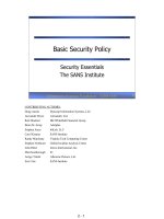
As mentioned earlier, there are two types of Ethernet—Ethernet 802.3 and
Ethernet_II. There are four frame type formats that are supported in Ethernet.
The frame formats vary for each of these Ethernet types. Figure 4.3 displays the
PC-1 has
data to send
PC-2 has
data to send
PC-3 has no
data to send
PC-4 has no
data to send
Collision
occurs
Figure 4.2 Using Ethernet devices to send data using CSMA/CD.
8
○○○○○○○○○○○○○○○○○○○○○○○○○○○○○○○○○○○○○○○○
Chapter 4
four Ethernet frame formats, which can contain the Ethernet_II, Ethernet 802.3,
Ethernet 802.2, and the SNAP Ethernet frame.
Note: Previously, we mentioned that the minimum size of an Ethernet frame is 64
bytes. Now that we have introduced the preamble, it is crucial to note that while the
preamble is part of the Ethernet frame, it is not considered when determining size.
Thus, an Ethernet frame with a size of 64 bytes (minimum) or 1518 bytes
(maximum) has a preamble that is not counted in the frame size.
We will now cover what each field is responsible for in the four Ethernet frame types.
Ethernet_II has the following frame format parameters:
➤ Preamble (8 bytes)—The preamble is used to synchronize all stations.
➤ Destination Address (6 bytes)—The destination address can be unicast (spe-
cific device), multicast (group of addresses), or broadcast (all devices).
➤ Source Address (6 bytes)—The source address identifies the sender.
➤ Type (2 bytes)—The type field describes the protocol been carried in the frame.
➤ Data (46 to 1,500 bytes)—The data field carries end user information, such as
an email message.
➤ Frame Checksum (4 bytes)—This frame checks sequence and calculates all fields,
except the preamble and the frame checksum (FCS), to make sure the frame
is not corrupted.
(All lengths in bytes)
Ethernet_II Frame
Preamble
8
DA
6
SA
6
Type
2
Data
46 to 1500
FCS
4
Ethernet 802.3 Frame
Preamble
8
DA
6
SA
6
Length
2
802.2 or SNAP Header (see below)
46 to 1500
FCS
4
Ethernet 802.2 Frame
Preamble
8
DA
6
SA
6
Length
2
802.2 Field
DSAP
1
SSAP
1
CTRL
1
Data
46 to 1497
FCS
4
Ethernet SNAP Frame
Preamble
8
DA
6
SA
6
Length
2
AA
1
AA
1
CTRL
1
Data
46 to 1496
Ethernet Type
1
FCS
4
SNAP Fields
Figure 4.3 Four Ethernet frame types.
9
○○○○○○○○○○○○○○○○○○○○○○○○○○○○○○○○○○○○○○○○
Basic Networking Technologies
The total length of an Ethernet frame must never exceed 1,518 bytes,
or a frame called a
giant
will be generated. The smallest frame size is
64 bytes. A frame smaller than 64 bytes is called a
runt
.
Ethernet 802.3 has the following frame format parameters:
➤ Preamble (8 bytes)—The preamble is used to synchronize all stations.
➤ Destination Address (6 bytes)—The destination address can be unicast (spe-
cific device), multicast (group of addresses), or broadcast (all devices).
➤ Source Address (6 bytes)—The source address identifies the sender.
➤ Length (2 bytes)—The length field describes data length.
➤ Data (46 to 1,500 bytes)—The data field carries end user information, such as
an email message.
➤ Frame Checksum (4 bytes)—This frame checks sequence and calculates all fields,
except the preamble and the frame checksum (FCS), to make sure the frame
is not corrupted.
The main difference between Ethernet_II and Ethernet 802.3 is that
Ethernet_II has a type field and 802.3 has a length field. If the contents
of this field exceed a value of 1,518, devices will know they are in
possession of a Ethernet_II frame and read the field as a type field. If
the value is less than 1,518, the field is treated as a length field.
Ethernet 802.2 has the following frame format parameters:
➤ Preamble (8 bytes)—The preamble is used to synchronize all stations.
➤ Destination Address (6 bytes)—The destination address can be unicast (spe-
cific device), multicast (group of addresses), or broadcast (all devices).
➤ Source Address (6 bytes)—The source address identifies the sender.
➤ DSAP (1 byte)—The Destination Service Access Point field together with
the SSAP define the source and destination protocol of the frame.
➤ SSAP (1 byte)—The Source Service Access Point field together with the DSAP
define the source and destination protocol of the frame.
➤ CTRL (1 byte)—The control field.
➤ Data (46 to 1,497 bytes)—The data field carries end user information, such as
an email message.
10
○○○○○○○○○○○○○○○○○○○○○○○○○○○○○○○○○○○○○○○○
Chapter 4
➤ Frame Checksum (4 bytes)—This frame checks sequence and calculates all fields,
except the preamble and the frame checksum (FCS), to make sure the frame
is not corrupted.
Note: With an IPX packet, the 802.2 header is set to E0 E0 03.
Ethernet SNAP header has the following frame format parameters:
➤ Preamble (8 bytes)—The preamble is used to synchronize all stations.
➤ Destination Address (6 bytes)—The destination address can be unicast (spe-
cific device), multicast (group of addresses), or broadcast (all devices).
➤ Source Address (6 bytes)—The source address identifies the sender.
➤ DSAP (1 byte)—The Destination Service Access Point field together with
the SSAP define the source and destination protocol of the frame. For a SNAP
frame, this field is set to AA.
➤ SSAP (1 byte)—The Source Service Access Point field together with the DSAP
define the source and destination protocol of the frame. For a SNAP frame,
this field is set to AA.
➤ CTRL (1 byte)—The control field.
➤ Data (46 to 1,496 bytes)—The data field carries end user information, such as
an email message. For a SNAP frame will include a type field that will iden-
tify the payload type like IP for example.
➤ Frame Checksum (4 bytes)—This frame checks sequence and calculates all fields,
except the preamble and the frame checksum (FCS), to make sure the frame
is not corrupted.
In the Control Fields (CTRL), 03 indicates Logical Link Control Type I or
datagram service. In Ethernet_II, the type field identifies the
payload
or
end user data
. Some common type field examples include the following:
➤
0x0800
—TCP/IP
➤
0x6004
—Local Area Transport (LAT)
➤
0x8037
—IPX
Table 4.2 summarizes a number of standards for Ethernet. Notice that Ethernet
802.3 and Ethernet_II run at 10Mbps. This was found to be too slow for today’s
networks, so a new standard was developed, called Fast Ethernet.
Table 4.2 displays three different physical Ethernet standards used in Ethernet
networks. The first two digits display the speed (in this case 10, it could be 100 or
11
○○○○○○○○○○○○○○○○○○○○○○○○○○○○○○○○○○○○○○○○
Basic Networking Technologies
1,000 for example), the word Base identifies this as baseband (BASE, where one
carrier frequency is used), and finally the last digit identifies the length and cable
type. For example,10BaseT is 10Mb Ethernet, Baseband, Unshielded twisted pair
and a maximum length of 100m.
Fast Ethernet
Fast Ethernet operates at 100Mbps. Fast Ethernet’s frame format and MAC
addresses are the same as Ethernet’s frame format and MAC addresses. The major
differences between Ethernet and Fast Ethernet is that Fast Ethernet can oper-
ate over many types of physical layer connections, including four pair twisted pair
cable. Another major difference is that Fast Ethernet, when cabled with twisted
pair cable, has a maximum network diameter of only 205 meters. Both Ethernet
and Fast Ethernet use CSMA/CD to gain access to media. Table 4.3 summa-
rizes a number of standards for Fast Ethernet (802.3u).
Today, an even faster version of Ethernet is available, called Gigabit Ethernet.
Gigabit Ethernet allows transmissions rates up to 1,000Mbps.
Gigabit Ethernet
Gigabit Ethernet is a recent development that enables transmissions up to
1,000Mbps. Gigabit Ethernet is an extension of the IEEE 802.3 standard and
was developed to meet the needs of an industry that demands more bandwidth
as time goes by. Gigabit Ethernet uses the same frame formats and MTU sizes,
and uses the CSMA/CD algorithm as well. 802.3z defines Gigabit Ethernet.
(For more information about Gigabit Ethernet, visit the IEEE Web site at
www.ieee.com.)
Table 4.2 Ethernet (802.3) characteristics.
Ethernet Standard Characteristic
10BaseT 10Mbps over two pair twisted cable. Maximum length 100m.
10Base2 10Mbps over coaxial cable (RG58). Maximum length 185m.
10Base5 10Mbps over thick Ethernet. Maximum length 500m.
Table 4.3 Three Fast Ethernet (802.3u) characteristics.
Ethernet Standard Characteristic
100Base-Tx 100Mbps over two pair twisted wire. Maximum length 100m.
100Base-T4 100Mbps over four pairs of category 3, 4, or 5 cable.
Maximum length 100m.
100Base-Fx 100Mbps over two strands of fiber. Maximum length 400m.
12
○○○○○○○○○○○○○○○○○○○○○○○○○○○○○○○○○○○○○○○○
Chapter 4
Verifying Ethernet Operation
Now that we’ve talked a little bit about theory, let’s look at a Cisco router’s statis-
tical display on a 10Mbps Ethernet interface and review the fields you need to be
aware of that are provided to you in a show interface command. Listing 4.1 pro-
vides a sample Ethernet statistical display taken from a Cisco router.
Listing 4.1 The show interface Ethernet0 command.
Ethernet0 is up, line protocol is up
Hardware is Lance, address is 0000.0c92.2ed4
Internet address is 10.99.34.50/24
MTU 1500 bytes,BW 10000 Kbit,DLY 1000 usec,rely 255/255,load 1/255
Encapsulation ARPA, loopback not set, keepalive set (10 sec)
ARP type: ARPA, ARP Timeout 04:00:00
Last input 00:00:00, output 00:00:00, output hang never
Last clearing of "show interface" counters never
Queuing strategy: fifo
Output queue 0/40, 0 drops; input queue 0/75, 0 drops
5 minute input rate 2000 bits/sec, 2 packets/sec
5 minute output rate 1000 bits/sec, 2 packets/sec
533880 packets input, 74463913 bytes, 0 no buffer
Received 524894 broadcasts, 0 runts, 0 giants, 0 throttles
0 input errors, 0 CRC, 0 frame, 0 overrun, 0 ignored, 0 abort
0 input packets with dribble condition detected
94282 packets output, 8713055 bytes, 0 underruns
1 output errors, 141 collisions, 2 interface resets
0 babbles, 0 late collision, 230 deferred
0 lost carrier, 0 no carrier
0 output buffer failures, 0 output buffers swapped out
The following list highlights the most important fields relative to troubleshoot-
ing and understanding how Ethernet is operating:
➤ MTU—Maximum transmission unit.
➤ BW—Interface bandwidth, measured in Kbps.
➤ DLY—Interface delay, measured in microseconds.
➤ rely—Reliability of the interface; 255 out of 255 means the interface is 100
percent reliable.
➤ load—Interface load; 255/255 means the interface is 100 percent loaded.
➤ ARP type—Type of Address Resolution Protocol assigned.
➤ packets input—Total number of error-free packets received by the system.
➤ bytes—Total number of bytes received by the interface. (Note that this is on
the same line as packets input.)
13
○○○○○○○○○○○○○○○○○○○○○○○○○○○○○○○○○○○○○○○○
Basic Networking Technologies
➤ no buffers—Number of packets discarded because the router had no available
buffers to store the packet before delivery. (Broadcast storms can typically
make this number high, because the router might not be able to handle the
amount of packets received.)
➤ Received broadcasts—Broadcast or multicast packets received by the interface.
➤ runts—Packets less than the minimum 64 bytes required for Ethernet.
➤ giants—Packets greater than the maximum allowable frame size in Ethernet.
Maximum frame size is set to 1,500 on Cisco router (MTU 1500).
➤ input errors—Number of runts, giants, no buffer available, CRC, frame, over-
run, and ignored counts.
➤ CRC—Cyclic redundancy checksum. Calculated by the source station and
checked by the router.
➤ frame—Number of frames received that have incorrect checksum errors.
➤ overrun—Number of times the receiver hardware was unable to hand re-
ceived data to a hardware buffer because the input rate exceeded the receiver’s
ability to handle the data.
➤ ignored—An internal condition on the router that indicates how many times
the interface runs low on internal buffers.
➤ input packets—A dribble bit error that indicates that a frame is slightly
too long.
➤ with dribble—Number of packets that have been seen by the router that are
slightly larger than the maximum frame size.
➤ packets output—Total number of messages transmitted by the system.
➤ bytes—Total number of bytes put out by the interface.
➤ underruns—Number of times the transmitter (Tx) has run faster than the
router can handle.
➤ output errors—Sum of all errors.
➤ collisions—Number of collisions detected by the router on the local Ethernet.
➤ interface resets—Number of times the interface has been reset. Interface re-
sets can occur manually with the clear interface E0 command or due to an
error condition on the segment, such as excessive broadcasts.
The preceding fields are important when troubleshooting Ethernet networks from
the viewpoint of a Cisco router. For example, an interface that reports a high
number of collisions is indicative of a device that might be faulty on the network.
14
○○○○○○○○○○○○○○○○○○○○○○○○○○○○○○○○○○○○○○○○
Chapter 4
Note: The interface command show interface fastethernet followed by the interface
number displays the same statistical display shown by the show interface Ethernet0
command. The notable difference is the bandwidth parameter, which is set to
100000 Kbit as opposed to 10000 Kbit for Ethernet.
The overriding benefits of Ethernet are that it’s cheap and easy to install. Further,
with Gigabit Ethernet’s recent developments, the future looks good. Now, let’s
turn to the most common networking technology used in the late 1970s and
’80s—Token Ring.
Token Ring 802.5
Token Ring networking was developed by IBM and Texas Instruments in the
1970s in response to the growing popularity of the personal computer. The IEEE
committee defined Token Ring in 802.5 to provide a standard to be used by non-
IBM devices.
In a Token Ring network, a device must have possession of the token frame before
it can transmit data onto the ring. Possession of the token frame allows a device
to send data onto the ring. Without a token frame, devices are not permitted to
transmit. Hence, Token Ring networks are sometimes called deterministic, be-
cause the possession of a free token determines whether a device can transmit
across a medium. Figure 4.4 displays a typical scenario where a group of devices
attached to the ring must wait for a free token before data can be sent across the
network. The free token is placed onto the ring once a device has finished send-
ing data. Token Ring networks are deterministic because each station has equal
access to the token and, therefore, equal access to the network. The token rotates
through the ring in a predictable fashion.
In a Token Ring network, a station must wait for the token to be available before
it can send data on to the ring. After a device possesses the token, the device can
then send data. The data is circulated around the ring until the destination device
has copied the frame and returned the frame into the ring. Then, the sending
device must remove the frame from the ring and place the free token back onto
the ring. The exception to this rule is in the case of early release, when the receiv-
ing station can release the free token.
Token Ring 802.5 can run at two speeds—4Mbps and 16Mbps. To modify the
ring speed on a Cisco router, you use the following IOS command:
ring-speed <4 or 16>
In summary format, the main characteristics of Token Ring 802.5 are:
➤ Star topology
➤ Star cabling