Slide điện tử tương tự chapter 5 frequency response
Bạn đang xem bản rút gọn của tài liệu. Xem và tải ngay bản đầy đủ của tài liệu tại đây (646.36 KB, 26 trang )
.c
om
ng
co
an
th
ng
DR. PHẠM NGUYỄN THANH LOAN
cu
u
du
o
CHAPTER 5: FREQUENCY RESPONSE
Hà Nội, 9/24/2014
CuuDuongThanCong.com
/>
ng
co
an
th
ng
du
o
u
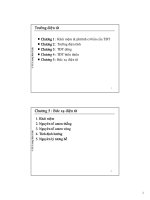
Introduction
Models
Low frequency response
Miller effect
High frequency response
cu
.c
om
Frequency Response
CuuDuongThanCong.com
/>
Relation of gain and input
frequency: Bode diagram
cu
u
du
o
ng
th
an
co
ng
.c
om
Introduction
CuuDuongThanCong.com
/>
.c
om
Introduction
f1 : fc at low frequency region
f2: fc at high frequency region
cu
u
du
o
ng
th
an
co
ng
Cut-off frequency (fc): gain
decrease of 3dB (0.707)
CuuDuongThanCong.com
/>
.c
om
Filter models
…. pass filter
cu
u
du
o
ng
th
an
co
ng
…. pass filter
CuuDuongThanCong.com
/>
.c
om
Filter models
High pass filter
cu
u
du
o
ng
th
an
co
ng
Low pass filter
CuuDuongThanCong.com
/>
u
du
o
ng
th
an
co
ng
.c
om
High pass filter
cu
Equivalent capacitor
short circuit at high frequency
open circuit at low frequency
CuuDuongThanCong.com
/>
Model
.c
om
pass filter
u
du
o
ng
th
an
co
ng
Low frequency
Open-circuit equivalent Capacitor
=>
Vo=0, Av=0
cu
- High
CuuDuongThanCong.com
High frequency
Short - circuit equivalent Capacitor
=> Vo=Vi, Av=1
/>
Model
pass filter
u
du
o
ng
th
an
co
ng
.c
om
- Low
cu
Equivalent capacitor
short circuit at high frequency
open circuit at low frequency
CuuDuongThanCong.com
/>
Model
.c
om
pass filter
th
an
co
ng
Low frequency,
Open-circuit eq. capacitor
=>
Vo= Vi , Av= 1
ng
du
o
u
cu
- Low
CuuDuongThanCong.com
High frequency,
Short-circuit eq. capacitor
=> Vo= 0 , Av=0
/>
Model
frequency
cu
u
du
o
ng
th
an
co
ng
.c
om
- Cut-off
CuuDuongThanCong.com
/>
Model
frequency
co
ng
fc: gain reduces 0,707 times (3dB)
.c
om
- Cut-off
2
w C
2
1
2
du
o
ng
R
2
th
AV
an
R
cu
u
w 2 f
f
1
2 R C
CuuDuongThanCong.com
/>
.c
om
Low frequency response
EC amplifier
Low frequency can be
determined from:
Cin (fLs) at input
Cout (fLo) at output
Cemitter (fLe)
f1 = fL = Max( fLs, fLo, fLe )
cu
u
du
o
ng
th
an
co
ng
CuuDuongThanCong.com
/>
cu
u
du
o
ng
th
an
co
ng
.c
om
fc introduced by input capacitor
with
f LS
1
2 ( R S R i )C S
CuuDuongThanCong.com
R
i
R 1 / / R 2 / / re
/>
cu
u
du
o
ng
th
an
co
ng
.c
om
fc introduced by output capacitor
f Lo
1
2 ( R o R L )C C
CuuDuongThanCong.com
with
R
O
R C / / r0
/>
cu
u
du
o
ng
th
an
co
ng
.c
om
fc introduced by emitter capacitor
f LE
1
2 R eC E
CuuDuongThanCong.com
with R
e
R E / / ( re R S / )
/>
co
VDD
Cc
th
VDD
an
5V
ng
RD
Rsig
7
Q1
u
5
du
o
1
CG
cu
4
Vs
3
RG
Similar to BJT amplifier
3 capacitors: mCG, CC, CS
fLG=1/[2π(Rsig+Ri)CG] with
Ri=RG
fLC=1/[2π(Ro+RL)CC] with
Ro=RD//rd
fLs=1/[2π(ReqCs] with
Req=Rs/[1+Rs(1+gmrd)/(rd+R
D//RL)]
ng
.c
om
FET amplifier
6
RL
RS
Cs
0
CuuDuongThanCong.com
/>
u
Cf: feedback capacitor
Inverting amplifier
Equivalent of Input and output capacitance
CMin = (1-Av)Cf
CMout = (1-1/Av)Cf ≈ Cf when Av is very big
cu
du
o
ng
th
an
co
ng
.c
om
Miller effect
CuuDuongThanCong.com
/>
Vùng tần số cao bị giới
hạn bởi các khâu lọc
thông thấp do các tụ kí
sinh Cbc, Cce, Cbe, Cwi,
Cwo
cu
u
du
o
ng
th
an
co
ng
.c
om
High frequency response
EC amplifier
CuuDuongThanCong.com
/>
du
o
ng
th
an
co
ng
.c
om
High frequency response
EC amplifier
cu
u
Ci=CWi+Cbe+CMi
CuuDuongThanCong.com
Co=CWo+Cce+CMo
/>
cu
u
du
o
ng
th
an
co
ng
.c
om
High frequency response
EC amplifier
CuuDuongThanCong.com
/>
cu
u
du
o
ng
th
an
co
ng
.c
om
How to choose cutoff frequency?
CuuDuongThanCong.com
/>
.c
om
High frequency response
FET amplifier
an
co
ng
VDD
th
Cc
6
Q1
Rsig
7
Cds
Cgs
cu
u
4
RD
1
du
o
5
VDD
Cgd
ng
CG
5V
3
Vs
RG
RS
CWi
RL
Cs
0
Tham khảo 11.10 trang 546, Electronic devices and circuit theory
CuuDuongThanCong.com
/>
CWo
u
du
o
ng
th
an
co
ng
Given Bode diagram
cu
.c
om
Determine ao, ao(dB) bandwidth, fc?
CuuDuongThanCong.com
/>
ng
co
an
th
ng
du
o
u
A)Determine voltage gain
B) Determine fLs, flC, FlE
C) Determine fHi, fH0
D) Plot Bode diagram
cu
.c
om
Example
CuuDuongThanCong.com
/>