Tài liệu Silicon_Wafer_Processing pdf
Bạn đang xem bản rút gọn của tài liệu. Xem và tải ngay bản đầy đủ của tài liệu tại đây (1.41 MB, 15 trang )
Silicon Wafer Processing
Dr. Seth P. Bates
Applied Materials
Summer, 2000
Objective
To provide an overview for manufacturing systems students of the steps and processes required to make
integrated circuits from blank silicon wafers.
Goals
The Transfer Plan provides a curriculum covering the process of manufacturing integrated circuits from
the silicon wafer blanks, using the equipment manufactured by Applied Materials, Lam Research, and
others of its competitors. The curriculum will be modular, with each module covering a process in
sequence. This curriculum will be developed for internet access.
Outline
Introduction
Preparation of the Silicon Wafer Media
Silicon Wafer Processing Steps
Seth Bates SJSU / Applied Materials / IISME-ETP page 1
Silicon Wafer Processing
Outline of Contents
Introduction................................................................................................................2
Preparation of the Silicon Wafer Media......................................................................3
Crystal Growth and Wafer Slicing Process
Thickness Sorting
Lapping & Etching Processes
Thickness Sorting and Flatness Checking
Polishing Process
Final Dimensional and Electrical Properties Qualification
Silicon Wafer Processing Steps.................................................................................8
Fabrication
Diffusion
Coat-Bake
Align
Develop
Dry etch
Wet etch & clean
Photolithography
Implant / Masking Steps
Die Attach / Wire Bond
Encapsulation
Lead Finish / Trim and Form
Final Testing / Shipping
Seth Bates SJSU / Applied Materials / IISME-ETP page 2
Introduction
The processing of Silicon wafers to produce integrated circuits involves a good deal of chemistry and
physics. In order to alter the surface conditions and properties, it is necessary to use both inert and toxic
chemicals, specific and unusual conditions, and to manipulate those conditions with both plasma-state
elements and with RF (Radio Frequency) energies. Starting with thin, round wafers of silicon crystal, in
diameters of 150, 200, and 300mm, the processes described here build up a succession of layers of
materials and geometries to produce thousands of electronic devices at tiny sizes, which together
function as integrated circuits (ICs). The devices which now occupy the surface of a one-inch square IC
would have occupied the better part of a medium-sized room 20 years ago, when all these devices
(transistors, resistors, capacitors, and so on) were only available as discreet units.
The conditions under which these processes can work to successfully transform the silicon into ICs
require an absolute absence of contaminants. Thus, the process chambers normally operate under
vacuum, with elemental, molecular, and other particulate contaminants rigorously controlled. In order to
understand these processes, then, we will begin the study of semiconductor processing with an overview
of vacuum systems and theory, of gas systems and theory, as applied specifically to these tools, and of
clean room processes and procedures
The semiconductor industry reflects and serves an extraordinary revolution in both materials science and
in data processing and storage. As recently as 1980, most individuals had no idea that computers would
ever impact their personal lives. Today, many families own one or two computers, and use many other
computers and dedicated processor systems in their appliances and automobiles. The intrusion of
electronics and computer technology into our lives and the devices we use daily is growing at an
exponential rate, and Moore’s Law still applied in the computer world. This is one of the few markets in
which, as time passes, the power and capacity of the products grows steadily, while the cost of that
power and capacity drops.
Today, only twenty years later, we are continually pushing the envelope of capabilities of the data
processing and storage systems that are now in the mainstream. Ingenuity and creativity, along with
great strides in quality control, process control, and worker productivity, are leading daily to new ideas
about how to further reduce device size and data density. On the horizon are visions of biochemically-
based devices which will be far smaller, work faster, and generate less heat than current devices. It is
worth spending some time imagining where this evolving technology will take us, and the society we
live in.
Seth Bates SJSU / Applied Materials / IISME-ETP page 3
Preparation of the Silicon Wafer Media
From:
Wafer products are measured at various stages of the
process to identify defects inducted by the manufacturing
process. This is done to eliminate unsatisfactory wafer
materials from the process stream and to sort the wafers
into batches of uniform thickness and at a final inspection
stage. These wafers will become the basic raw material for
new integrated circuits. The following is a summary of the
steps in a typical wafer manufacturing process.
Crystal Growth and Wafer Slicing Process
The first step in the wafer manufacturing
process is the formation of a large, perfect silicon crystal. The
crystal is grown from a ‘seed crystal’ that is a perfect crystal.
The silicon is supplied in granular powder form, then melted in
a crucible. The seed is immersed carefully into the crucible of
molten silicon, then slowly withdrawn.
Step 1: Obtaining the Sand
The sand used to grow the wafers has to be a very clean and good form of silicon. For this reason not just
any sand scraped off the beach will do. Most of the sand used for these processes is shipped from the
beaches of Australia.
Step 2: Preparing the Molten Silicon Bath
The sand (SiO
2
)is taken and put into a crucible and is heated to about 1600 degrees C – just above its
melting point. The molten sand will become the source of the silicon that will be the wafer.
Step 3: Making the Ingot
A pure silicon seed crystal is now placed into the molten sand
bath. This crystal will be pulled out slowly as it is rotated. The
dominant technique is known as the Czochralski (cz) method.
The result is a pure silicon cylinder that is called an ingot. As
description or a variant on the Czochralski method is available at
/>
The Czochralski method
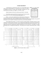
Silicon Thermal Properties
Thermal Conductivity (solid) 1.412 W/cm-K
Thermal Conductivity (liquid) 4.3 W/cm-K
Specific Heat 0.70 J/g-K
Thermal Diffusivity .9 cm**2/s
Melting Point 1683 K
Boiling Point 2628 K
Critical Temperature 5159 K
Density (solid) 2.33 g/cm**3
Density (liquid) 2.53 g/cm**3
Vapor pressure
at 1050C 1e-7 Torr
at 1250C 1e-5 Torr
Molar heat capacity 20.00 J/mol-K
Seth Bates SJSU / Applied Materials / IISME-ETP page 4
Examples of some completed ingots An epitaxial reactor.
Growth of Epitaxial Silicon
This step is done to provide a good clean surface for later processing. If a layer of Silicon is grown onto
the top of the wafer using chemical methods then that layer is of a much better quality then the slightly
damaged or unclean layer of silicon in the wafer. The
epitaxial layer is where the actual processing will be
done.
The diameter of the silicon ingot is determined by the
temperature variables as well as the rate at which the
ingot is withdrawn. When the ingot is the correct
length, it is removed, then ground to a uniform
external surface and diameter.
Each of the wafers is given either a notch or a flat
edge that will be used later in orienting the wafer into
the exact position for later procedures. In these two figures you can see a notch (above) and flats. Flats
in this image are exaggerated for clarity.
Step 4: Preparing the Wafers
After the ingot is ground into the correct diameter for the wafers, the
silicon ingot is sliced into very thin wafers. This is usually done with a
diamond saw.
A diamond saw for cutting wafers
Each of these wafers will then go through polishing until they are very smooth and just the right
thickness (see Polishing Process, below).
Thickness Sorting
Seth Bates SJSU / Applied Materials / IISME-ETP page 5
Following slicing, silicon wafers are often sorted on an automated basis into
batches of uniform thickness to increase productivity in the next process step,
lapping. During thickness sorting, the wafer manufacturer can also identify defect
trends resulting from the slicing process.
Lapping & Etching Processes
Lapping removes the surface silicon which has been cracked or otherwise damaged
by the slicing process, and assures a flat surface. Wafers are then etched in a
chemically active reagent to remove any crystal damage remaining from the
previous process step.
Thickness Sorting and Flatness Checking
Following lapping or etching, silicon wafers are measured for flatness to identify and control defect
trends resulting from the lapping and etching processes. Wafers are also often sorted on an automated
basis according to thickness in order to increase productivity in the next process step, polishing.
Polishing Process
Polishing is a chemical/mechanical process that smoothes the uneven surface left by the lapping and
etching processes and makes the wafer flat and smooth enough to support optical photolithography.
A wafer polishing machine Wafers in storage trays
Final Dimensional and Electrical Properties Qualification
The wafers undergo a final test, performed in order to demonstrate conformance with customer
specification for flatness, thickness, resistivity and type. Process induced defect and defect trend
information is used by the wafer manufacturer for yield and process management of the immediately
preceding steps. Information regarding surface defects, such as scratches and particles, and defect trend
information are used by the wafer manufacturer for yield and process improvement.