Tài liệu InDesign CS5 Bible- P8 pdf
Bạn đang xem bản rút gọn của tài liệu. Xem và tải ngay bản đầy đủ của tài liệu tại đây (1.07 MB, 50 trang )
Chapter 12: Applying Effects to Objects
305
Applying feathering
A similar option to drop shadows is feathering, which essentially softens the edges of objects.
Figures 12.12 through 12.14 show all three types of feathering.
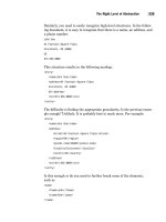
Applying basic feathering
To apply basic feathering, where the edges are blurred around all sides of an object, select the Basic
Feather option. The controls are simple:
l
In the Feather Width field, enter a value for the degree of feathering — smaller numbers
have the least effect; larger numbers have the most effect. The feathering area starts at the
outside edge of the object, so a larger number eats into the object, making it a wispier ver-
sion of itself.
l
The Choke field and pop-up menu let you set where the frame edge begins to get fuzzy
(a value of 0 starts immediately at the object edge, whereas a larger value pushes the fuzzy
part into the object).
l
The Noise field and pop-up menu let you add visual noise to the shadow, making it less
smooth as the value increases.
l
The Corners pop-up menu gives you three options:
l
Sharp
l
Rounded
l
Diffused
The Sharp option retains the original corner shape as much as possible. The Rounded
option rounds the corners of the object; it can distort the shape dramatically at larger
Feather Width settings. The Diffused option creates a soft, almost smoky effect by making
the object borders and corners more translucent.
FIGURE 12.12
The Basic Feather pane of the Effects dialog box
20_607169-ch12.indd 30520_607169-ch12.indd 305 4/22/10 7:54 PM4/22/10 7:54 PM
Please purchase PDF Split-Merge on www.verypdf.com to remove this watermark.
Part III: Object Fundamentals
306
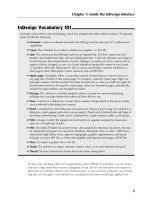
Applying directional feathering
The Directional Feather controls act like a drop shadow in that there is an external light source that
determines how the feathering’s blur appears along an object’s edges.
The effect is more like a shadowy smear. The controls are similar to that of Basic Feather, with
these exceptions:
l
Rather than have one Width setting, there are separate settings for the Top, Bottom, Left,
and Right. If the chain icon is a solid chain, all edges have the same width; click it to get
the broken-chain icon, which lets you control each edge independently.
l
The Shape pop-up menu lets you choose what edges are feathered: First Edge Only (the
ones specified in the Width fields), Leading Edges (any in the path of the light source),
and All Edges.
l
Set the light source angle by entering a value in the Angle field or by clicking a location in
the circle.
FIGURE 12.13
The Directional Feather pane of the Effects dialog box
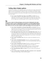
Applying gradient feathering
The Gradient Feather controls create the effect of having a strong light source near the object,
washing out part of the object. Here’s how the controls work:
l
You set the gradient itself in the Gradient Stops area. You add stop points, choose opacity
for each, and set the location for both gradient stops and transition points just as you do
for any gradient (see Chapter 8). You can reverse the gradient’s direction by clicking the
iconic button to the right of the gradient ramp.
l
In the Options area, you set the gradient type — Linear or Radial — and the lighting angle.
20_607169-ch12.indd 30620_607169-ch12.indd 306 4/22/10 7:54 PM4/22/10 7:54 PM
Please purchase PDF Split-Merge on www.verypdf.com to remove this watermark.
Chapter 12: Applying Effects to Objects
307
FIGURE 12.14
The Gradient Feather pane of the Effects dialog box
Cross-Reference
You can also apply gradient feathering using the Gradient Feather tool, as described in Chapter 8.
n
Applying outer and inner glows
Glows are what they sound like: A lighting effect that makes it seem as if there is light behind an
object that causes it to glow (an outer glow) or a light source within the object’s frame that causes
a glow inside (an inner glow). Figure 12.15 and Figure 12.16 show the panes.
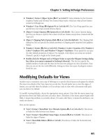
Applying an outer glow
Here’s how the controls for outer glow work (note that the first three options are the same as for
transparency effects):
l
Choose the blending mode in the Mode pop-up menu, the glow color in the Color pop-up
menu (the square swatch to the right of the Mode pop-up menu), and the transparency
level in the Opacity field or pop-up menu.
l
Choose the glow’s intensity by choosing Software or Precise in the Technique pop-up
menu. The Precise option creates a more saturated, harsher glow.
l
Choose how far away from the frame the glow begins to dissipate by entering a value in
the Spread field. A value of 0 starts the fade immediately.
l
Choose the width of the glow in the Size field.
l
Add visual noise to the shadow, making it less smooth as the value increases, by entering a
value in the Noise field or choosing a value from the pop-up menu.
20_607169-ch12.indd 30720_607169-ch12.indd 307 4/22/10 7:54 PM4/22/10 7:54 PM
Please purchase PDF Split-Merge on www.verypdf.com to remove this watermark.
Part III: Object Fundamentals
308
FIGURE 12.15
The Outer Glow pane of the Effects dialog box
Applying an inner glow
The controls for inner glows are nearly identical to those for outer glows, with these two exceptions:
l
The Spread field in the Options area is called Choke. It does the same as Spread but
applies inside the frame rather than outside of it.
l
The Source options — Center and Edge — let you choose the light source’s location
relative to the object.
FIGURE 12.16
The Inner Glow pane of the Effects dialog box
20_607169-ch12.indd 30820_607169-ch12.indd 308 4/22/10 7:54 PM4/22/10 7:54 PM
Please purchase PDF Split-Merge on www.verypdf.com to remove this watermark.
Chapter 12: Applying Effects to Objects
309
Applying beveling and embossing
Beveling means to make an object appear to be above the plane of other objects, thus casting a
shadow at the edges. Embossing is a variation of beveling where only the edges are raised; the con-
tents are lowered back to the normal plane. Figure 12.17 shows the Bevel and Emboss pane.
FIGURE 12.17
The Bevel and Emboss pane of the Effects dialog box
The controls for beveling and embossing combine controls from several other lighting effects:
l
In the Structure area, choose the bevel or emboss style from the Style pop-up menu:
Outer Bevel (the bevel extends outside the frame), Inner Bevel (the bevel extends inside
the frame), Emboss, and Pillow Emboss (a shallower embossing).
l
In the Technique pop-up menu, choose the type of shadow effects: Smooth, Chisel Hard,
and Chisel Soft.
l
Choose the apparent height of the effect by entering a value in the Depth field or using the
Depth slider. Similarly, choose the shadow’s thickness by entering a value in the Size field.
l
Choose the direction of the effect by selecting either Up (raised) or Down (etched out) in
the Direction pop-up menu.
l
Adjust the shadow’s intensity by entering a value in the Soften field.
l
In the Shading area, choose the light source’s direction by entering a value in the Angle
field, clicking a point in the circle, or checking the Use Global Light option. Similarly,
adjust the light source’s height in the Altitude field.
l
Adjust the blending mode applied to areas of the bevel or emboss that the light hits by
using the Highlight Mode pop-up menu, and the blending mode applied to the shadowed
areas using the Shadow Mode pop-up menu. In both cases, there is also a combination
field and pop-up menu labeled Opacity where you can adjust the effect’s transparency.
20_607169-ch12.indd 30920_607169-ch12.indd 309 4/22/10 7:54 PM4/22/10 7:54 PM
Please purchase PDF Split-Merge on www.verypdf.com to remove this watermark.
Part III: Object Fundamentals
310
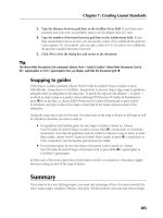
Applying satin effects
The satin effect is similar to a glow, except that it applies a shadow to the frame’s edges, as if the
object were made of satin cloth and bowed slightly out from its edges. Figure 12.18 shows the
Satin pane.
FIGURE 12.18
The Satin pane of the Effects dialog box
To apply a satin effect:
l
Choose the blending mode in the Mode pop-up menu, the glow color in the Color pop-up
menu (the square swatch to the right of the Mode pop-up menu), and the transparency
level in the Opacity field or pop-up menu.
l
Choose the light source’s direction by entering a value in the Angle field, or by clicking a
point in the circle to designate the light’s location relative to the object (represented by the
center of the circle).
l
Choose the width of the satin effect in the Size field.
l
Specify the shadow’s size by typing a value in the Distance field.
l
To have the satin effect appear as if the object were sinking slightly from the edges (mak-
ing it darker), check Invert.
Summary
If you have a frame or shape selected, you can add a stroke around its border or add a color to its
background, as well as apply transparency to an object or its contents. You can apply strokes (and
colors) to lines and text as well.
20_607169-ch12.indd 31020_607169-ch12.indd 310 4/22/10 7:54 PM4/22/10 7:54 PM
Please purchase PDF Split-Merge on www.verypdf.com to remove this watermark.
Chapter 12: Applying Effects to Objects
311
The Eyedropper tool lets you sample much of the formatting of an object and then apply it to other
objects using the Marker tool.
You can further enhance these attributes with the corner-options capabilities, which let you apply
fancy shapes to one or more corners of an object. A new capability in InDesign CS5 lets you edit
the corners’ shape with the mouse.
InDesign has a broad palette of lighting effects capabilities, including inner shadow, glow, feather,
bevel, emboss, and satin effects, as well as more traditional transparency and drop shadow effects.
You can apply these effects to entire objects, to just their frames, just their fills, or just their text.
20_607169-ch12.indd 31120_607169-ch12.indd 311 4/22/10 7:54 PM4/22/10 7:54 PM
Please purchase PDF Split-Merge on www.verypdf.com to remove this watermark.
20_607169-ch12.indd 31220_607169-ch12.indd 312 4/22/10 7:54 PM4/22/10 7:54 PM
Please purchase PDF Split-Merge on www.verypdf.com to remove this watermark.
313
CHAPTER
Orchestrating Objects
IN THIS CHAPTER
Changing the stacking order of
objects
Working with groups
Locking objects
Nesting objects
Inserting objects within a text
thread
Anchoring objects to text
Setting text wrap
Working with object styles
Managing source links
Adding metadata captions
F
rames, shapes, lines, and paths are the building blocks with which
you construct InDesign pages. Becoming familiar with creating and
modifying individual objects, which is the focus of Chapters 9
through 12, is a key step in learning how to create publications with
InDesign. The next step is to learn how to use several features that let you
manipulate multiple objects simultaneously and quickly adjust the relation-
ships among the various objects that make up a page. A good InDesign user
can handle individual objects one at a time with ease; a virtuoso user can
simultaneously juggle several objects with equal ease.
Think of it this way: As an InDesign user, you’re much like an architect. You
begin with a blueprint — perhaps a rough, felt-tip pen sketch or maybe just
a graphic in your mind’s eye — open a new document, and start construc-
tion. The settings you establish in the New Document dialog box (choose
File ➪ New ➪ Document or press Ô+N or Ctrl+N) — the page size, margin
placement, column arrangement, and number of pages — serve as the foun-
dation as you begin adding objects to your pages.
You must then construct your building, or rather, your publication, using
four basic components:
l
Text frames
l
Graphics frames
l
Shapes
l
Lines
You can tweak and twist each of those components in a nearly endless vari-
ety of ways while retaining basic properties. After all, a sheared (skewed) and
21_607169-ch13.indd 31321_607169-ch13.indd 313 4/22/10 7:55 PM4/22/10 7:55 PM
Please purchase PDF Split-Merge on www.verypdf.com to remove this watermark.
Part III: Object Fundamentals
314
mirrored text frame with a purple dashed stroke, a gradient background, and magenta text out-
lined in cyan is still just a text frame.
As a publication evolves, plans invariably change: An advertiser pulls out and a magazine article
needs to be stretched an extra half-page by enlarging an InDesign-created illustration. A client
loves his company’s newsletter but wants the front-page graphic cropped differently. A new prod-
uct is added to a catalog and half the pages reflow. If you build your documents soundly from the
ground up and use the features covered in this chapter, you should be prepared to handle even the
most challenging page building — and rebuilding — tasks.
Stacking Objects
Each time you begin work on a new page, you start with a clean slate (unless the page is based on
a master page, in which case the master objects act as the page’s background; see Chapter 7 for
more on master pages). Every time you add an object to a page — either by using any of InDesign’s
object-creation tools or with the Place command (choose File ➪ Place or press Ô+D or Ctrl+D) —
the new object occupies a unique place in the page’s object hierarchy, or stacking order.
The first object you place on a page is automatically positioned at the bottom of the stacking order;
the next object is positioned one level higher than the first object (that is, on top of and in front of
the backmost object); the next object is stacked one level higher; and so on for every object you
add to the page. It’s not uncommon for a page to have several dozen or even several hundred
objects.
Tip
When building pages, always try to keep the number of objects to a minimum. For example, instead of putting
a headline in one text frame and a subhead in a separate text frame directly below the one that contains the
headline, use a single text frame. Lean documents save and print more quickly and are less problematic to
modify than bloated documents.
n
Although each object occupies its own level, if the objects on a page don’t overlap, then the stack-
ing order is not an issue. However, some of the most interesting graphic effects you can achieve
with InDesign involve arranging several overlapping objects, so it’s important to be aware of the
three-dimensional nature of a page’s stacking order.
Because objects are added in back-to-front order, it makes sense to build your pages from back to
front. For example, if you want to use a lightly tinted version of a scanned image as the back-
ground for a page, you first place the image on the page and then add other objects on top of or in
front of the graphics frame.
In an ideal world, the first object you place on a page would remain forever the backmost, the last
object would be the frontmost, and every object in between — created in perfect order from back
to front — would relate correctly with every other object. In this perfect world, you would never
have to worry about moving objects backward or forward.
21_607169-ch13.indd 31421_607169-ch13.indd 314 4/22/10 7:55 PM4/22/10 7:55 PM
Please purchase PDF Split-Merge on www.verypdf.com to remove this watermark.
Chapter 13: Orchestrating Objects
315
But the world is not perfect, and you may change your mind about what you want to achieve in
your layout after you’ve already placed objects in it. To change an object’s position in a page’s
stacking order, use the Arrange menu option (choose Object ➪ Arrange), which offers four sub-
menus:
l
Bring to Front (Shift+Ô+] or Ctrl+Shift+])
l
Bring Forward (Ô+] or Ctrl+])
l
Send to Back (Shift+Ô+[ or Ctrl+Shift+[)
l
Send Backward (Ô+[ or Ctrl+[)
For example, you might want to see how a piece of text looks in front of an illustration; but if you
create the text frame before you create or place the illustration, you have to move the text frame
forward (or the illustration backward) in the stacking order.
Cross-Reference
In addition to letting you change the stacking order of objects on a page, InDesign also lets you create docu-
ment-wide layers. Each layer contains a separate collection of stacked objects. You can both reorder individual
objects within a layer and reorder whole layers using the Layers panel. For more information about using lay-
ers, see Chapter 6.
n
To change the stacking order of objects:
1.
Use any of the object-creation tools to create four overlapping shapes, as shown in
Figure 13.1. The numbers in parentheses indicate the order in which you should create
the shapes.
FIGURE 13.1
Left: The first shape you create is the backmost, the second is one level above, and so on.
In this example, the three smaller boxes partially overlap each other and they are all in
front of the largest box. Right: Applying tints to the shapes lets you see the stacking order
of the four rectangles. Every InDesign object occupies one level in the stacking order.
21_607169-ch13.indd 31521_607169-ch13.indd 315 4/22/10 7:55 PM4/22/10 7:55 PM
Please purchase PDF Split-Merge on www.verypdf.com to remove this watermark.
Part III: Object Fundamentals
316
2.
If it’s not already displayed, open the Swatches panel by choosing
Window ➪ Color ➪ Swatches or pressing F6. You use this panel to change the shade of
each object so you can easily tell it apart from the others.
3.
Click the Selection tool, click the last object you created and then use the color
tools in the Tools panel or the Swatches panel to fill the object with a color.
Cross-Reference
See Chapters 8 and 12 for more information about applying fills and strokes to objects.
n
4.
Use the Swatches panel to fill each of the remaining boxes with a successively
lighter tint of the color, as shown in Figure 13.1. In the example, the remaining
shapes are tinted at 25 percent, 50 percent, and 75 percent, respectively.
5.
Click the frontmost shape (the last one you created) and then choose
Object ➪ Arrange ➪ Send Backward or press Ô+[ or Ctrl+[. Notice that the Bring to
Front and Bring Forward menu options are not available. That’s because you can’t move
the frontmost object any farther forward in the stacking order.
6.
Click the backmost shape (the first one you created) and then choose
Object ➪ Arrange ➪ Bring Forward or press Ô+] or Ctrl+]. When you bring the object
forward, one of the objects becomes obscured.
7.
Choose Object ➪ Arrange ➪ Bring to Front or press Shift+Ô+] or Ctrl+Shift+]. The
smaller shapes are now obscured by the largest one.
8.
Choose Object ➪ Arrange ➪ Send to Back or press Shift+Ô+[ or Ctrl+Shift+[. The
hidden objects are once again visible.
New Feature
To select an object partially obscured behind one or more objects, click a portion that is not covered, or hover
over it with the Selection tool and click the content grabber (the doughnut icon) in its center to select it.
n
To select an object completely hidden behind one or more other objects, press and hold Ô or Ctrl
and then click anywhere within the area of the hidden object. The first click selects the topmost
object; each successive click selects the next lowest object in the stacking order. When the bottom
object is selected, the next click selects the top object. If you don’t know where a hidden object is,
you can simply click the object or objects in front of it and then send the objects to the back.
Another way to select objects that are in a stack or group is to use the Select Previous Object or
Select Next Object iconic buttons in the Control panel. If you Shift+click either button, InDesign
jumps past four objects and selects the fifth one. If you Ô+click or Control+click either button,
InDesign selects to the bottommost or topmost object, respectively.
Cross-Reference
See Chapter 10 for more details on selecting objects.
n
21_607169-ch13.indd 31621_607169-ch13.indd 316 4/22/10 7:55 PM4/22/10 7:55 PM
Please purchase PDF Split-Merge on www.verypdf.com to remove this watermark.
Chapter 13: Orchestrating Objects
317
Combining Objects into a Group
InDesign lets you combine several objects into a group. A group of objects behaves like a single
object, which means that you can cut, copy, move, or modify all the objects in a group in a single
operation. Groups have many uses. For example, you might create a group to:
l
Combine several objects that make up an illustration so that you can move, modify, copy,
or scale all objects in a single operation.
l
Keep a graphics frame and its accompanying caption (text) frame together so that if you
change your mind about their placement, you can reposition both objects at one time.
l
Combine several vertical lines used to separate the columns of a table so that you can
quickly change the stroke, color, length, and position of all lines.
Tip
If you want to manipulate a group, select any object in the group with the Selection tool. The group’s bounding
box appears. Any transformation you perform is applied to all objects in the group. If you want to manipulate a
specific object in a group, choose the Direct Selection tool.
n
To create a group:
1.
Select all the objects you want to include in your group.
2.
Choose Object ➪ Group or press Ô+G or Ctrl+G.
That’s all there is to it. When you create a group from objects that do not occupy successive levels
in the stacking order, the objects are shuffled as necessary so that the grouped objects are stacked
on adjacent layers directly below the topmost object. If you create a group from objects on differ-
ent layers, all objects are moved to the top layer and stacked in succession beneath the topmost
object.
Cross-Reference
See Chapter 6 for more about layers.
n
Note
You cannot create a group if some of the selected objects are locked and some are not locked. All selected
objects must be locked or unlocked before you can group them. (Locking and unlocking objects is covered
later in this chapter.)
n
Using groups within groups
One nifty thing about groups is that you can include a group within a group. For example, all the
objects in Figure 13.2 — five stars and two circles (a gray circle and a white circle form the moon) —
have been grouped, making it easy to manipulate the whole illustration, but that’s not all. The stars
within the group are also a group. So are the two circles that make up the crescent moon. That is,
21_607169-ch13.indd 31721_607169-ch13.indd 317 4/22/10 7:55 PM4/22/10 7:55 PM
Please purchase PDF Split-Merge on www.verypdf.com to remove this watermark.
Part III: Object Fundamentals
318
first the stars were grouped together, then the two circles were grouped together, and finally the
group of stars was grouped with the circles that form the moon to create a larger group.
Grouping the stars makes it easy to change all of them at one time, as shown in Figure 13.2, and
grouping the two circles that make up the crescent moon makes it easy to move the moon.
Note
A group can contain as many levels of subgroups, or nested groups, as you want, but it’s best to keep things as
simple as you can. The more levels of nested groups you have within a group, the more work it is to ungroup
the objects.
n
FIGURE 13.2
The bounding box indicates that all the objects within it have been grouped (at left). What you can’t tell
from this illustration is that the five stars are a group within the larger group, which lets you move or mod-
ify all of them in a single operation, as shown at right.
Selecting objects within groups
The main reason you create groups in the first place is so that you can delete, copy, move, or mod-
ify all the objects at one time. However, sometimes you may want to modify an object within a
group. No problem. You don’t have to ungroup objects to modify an individual object. InDesign
offers several options for selecting objects — and nested groups — within groups. You can:
l
Select an individual object by clicking it with the Direct Selection tool. Note that — if the
group has not been selected — InDesign automatically selects an object as you hover the
Direct Selection tool over it.
l
Double-click an object in a group with the Selection tool to select just that object. You can
then single-click any other object in that group. (Double-clicking again selects the entire
group.) Note that if you want to select an empty frame or shape (one with neither a fill
nor contents), you must click the frame itself; clicking inside the frame won’t work when
the frame or shape is empty.
l
Select the bounding box of an individual object by clicking it with the Direct Selection
tool and then switching to the Selection tool.
21_607169-ch13.indd 31821_607169-ch13.indd 318 4/22/10 7:55 PM4/22/10 7:55 PM
Please purchase PDF Split-Merge on www.verypdf.com to remove this watermark.
Chapter 13: Orchestrating Objects
319
l
If you have selected an object in a group of objects, choose Object ➪ Select ➪ Previous
Object in Group to navigate to the previous object in the group, or choose Object ➪
Select ➪ Next Object in Group to navigate to the previous object in the group. Or use the
Select Previous Object or Select Next Object iconic buttons in the Control panel, as shown
in Figure 13.3. (You may need to first click the Select Content iconic button for these two
buttons to become available.)
l
Select multiple objects within a group by Shift+clicking each object with the Direct
Selection tool.
l
Select the bounding box of multiple objects within a group by Shift+clicking each object
with the Direct Selection tool and then switching to the Selection tool.
l
Select a nested group by clicking any object within the nested group with the Direct
Selection tool and then pressing and holding Option or Alt and clicking the object again.
Pressing and holding Option or Alt in this situation temporarily accesses the Group
Selection tool, indicated by a small plus sign (+) below and to the right of the arrow
pointer.
FIGURE 13.3
The selection buttons on the Control panel
Ungrouping
After creating a group, you may eventually decide that you want to return the objects to their origi-
nal, ungrouped state. To do so, simply click any object in the group with the Selection tool to
select the entire group and then choose Object ➪ Ungroup or press Shift+Ô+G or Ctrl+Shift+G. If
you ungroup a group that contains a group, the contained group is not affected. To ungroup this
subgroup, you must select it and then choose Ungroup again.
Locking Objects
If you’re certain that you want a particular object to remain where it is, you can choose
Object ➪ Lock or press Ô+L or Ctrl+L to prevent the object from being moved. (A lock icon
appears on the upper left of its frame edge; for paths, the lock appears toward the top of the path.)
Generally, you want to lock repeating elements such as headers, footers, folios, and page numbers
so that they’re not accidentally moved. (Such repeating elements are usually placed on a master
page; you can lock objects on master pages, too.)
21_607169-ch13.indd 31921_607169-ch13.indd 319 4/22/10 7:55 PM4/22/10 7:55 PM
Please purchase PDF Split-Merge on www.verypdf.com to remove this watermark.
Part III: Object Fundamentals
320
So what does locking do, exactly? A locked object can’t be moved whether you click and drag it
with the mouse or change the values in the X and Y fields in the Control panel or Transform panel.
Not only can you not move a locked object, but you can’t delete one, either.
However, you can change other attributes of a locked object, including its stroke and fill — unless
you disable selection of locked objects. To do so, select Prevent Selection of Locked Objects in the
General pane of the Preferences dialog box (which you open by choosing InDesign ➪ Preferences
or pressing Ô+K on the Mac or by choosing Edit ➪ Preferences or pressing Ctrl+K in Windows).
To unlock an object, choose Object ➪ Unlock All on Spread or press Option+Ô+L or Ctrl+Alt+L.
Note that this action unlocks all the objects on the current spread, not just whatever objects might
be selected.
New Feature
InDesign CS5 changes how unlocking works: You no longer unlock individual objects; instead, you now unlock
all objects on the current spread. InDesign CS5 has also changed the name of the menu option for locking from
Lock Position to simply Lock, and InDesign CS5 adds the Prevent Selection of Locked Objects option in the
Preferences dialog box’s General pane.
n
Cross-Reference
You can also lock entire layers, as described in Chapter 6.
n
InDesign lets you not only combine several objects into a group but also place an object within the
boundaries of a frame. Just as a group embedded within a larger group is said to be a nested group,
an object that’s been placed within another frame is said to be a nested object. When you place an
object within a frame, the containing frame acts as the cropping shape for the object within.
One of the more common uses of nested frames is for cropping imported graphics. When you
place a graphic onto a page, the graphic is automatically placed within a frame. (You can also place
a graphic within an existing frame.) You can reveal and hide different areas of the graphic by resiz-
ing or reshaping the container frame. Figure 13.4 shows an imported graphic that’s been placed
within a circular frame.
Clicking the graphic with the Direct Selection tool selects the nested object rather than the con-
tainer frame. To work on that nested object’s frame, you can then switch to the Selection tool after
the nested object is selected with the Direct Selection tool. To select the container frame’s bound-
ing box instead of the nested object, click the object with the Selection tool.
Cross-Reference
For more information about importing and modifying graphics, see Part IV.
n
21_607169-ch13.indd 32021_607169-ch13.indd 320 4/22/10 7:55 PM4/22/10 7:55 PM
Please purchase PDF Split-Merge on www.verypdf.com to remove this watermark.
Chapter 13: Orchestrating Objects
321
FIGURE 13.4
Left: In this example, the rectangle displayed with handles indicates the border of a graphic that’s been placed
into a triangular frame. Right: I created the squiggly line (left) with the Pen tool. I then copied and pasted it into
(Edit
➪
Paste Into) a circular frame (right). Selecting the line with the Direct Selection tool (not shown) would dis-
play the visible portion of the line within the oval cropping frame, as well as the cropped parts of the line.
As you can with groups, you can place a frame within a frame within a frame and so on, to create
as many nested levels as you want. The same caveat applies: Keep things as simple as possible to
achieve the desired effect. To nest a frame within a frame:
1.
Select the frame you want to nest within another frame.
2.
Choose Edit ➪ Copy or press Ô+C or Ctrl+C.
3.
Select the frame into which you want to place the copied object and then choose
Edit ➪ Paste Into or press Option+Ô+V or Ctrl+Alt+V. Figure 13.4 shows a before/
after example of a squiggly line that’s been pasted into a circular frame that serves as the
masking shape for the line.
Tip
Selecting nested objects can be tricky. In general, the same selection techniques that work with groups also
work with nested frames. If you need to modify text within a nested or grouped text frame, simply click within
the frame with the Type tool.
n
Creating Inline Frames
In most cases, you want the objects you place on your pages to remain precisely where you put
them. However, sometimes you want to place objects relative to related text in such a way that the
objects move when the text is edited. For example, if you’re creating a product catalog that’s essen-
tially a continuous list of product descriptions and you want to include a graphic with each
description, you can paste graphics within the text to create inline graphics frames.
21_607169-ch13.indd 32121_607169-ch13.indd 321 4/22/10 7:55 PM4/22/10 7:55 PM
Please purchase PDF Split-Merge on www.verypdf.com to remove this watermark.
Part III: Object Fundamentals
322
An inline frame is treated like a single character. If you insert or delete text that precedes an inline
frame, the frame moves forward or backward along with the rest of the text that follows the
inserted or deleted text. Although inline frames usually contain graphics, they can just as easily
contain text or nothing at all.
Caution
Inline frames may interfere with line spacing in paragraphs with automatic leading. If the inline frame is larger
than the point size in use, the automatic leading value for that line is calculated from the inline frame. This
leads to inconsistent line spacing in the paragraph. To work around this, you can either apply a fixed amount of
leading to all characters in the paragraph, adjust the size of inline frames, place inline frames at the beginning
of a paragraph, or place inline frames in their own paragraphs.
n
There are three ways to create inline frames. The first two are the simplest, but the third, using the
Anchored Object command, gives you more control over the inline frame when you create it.
Note
You can set text wraps on inline frames using the standard Text Wrap panel (choose Window ➪ Text Wrap, or
press Option+Ô+W or Ctrl+Alt+W), as described later in this chapter. However, note that such wraps affect
only text that appears on the same line or below the inline frame, not text above the inline frame or text in
other frames.
n
Tip
To delete an inline frame, you can select it and then choose Edit ➪ Clear or Edit ➪ Cut, or you can position the
text cursor next to it and then press Delete or Backspace.
n
Creating an inline frame with the Paste command
If you want to create an inline frame from an object you’ve already created, all you have to do
is copy or cut the object and then paste it into text as you would a piece of highlighted text.
Here’s how:
1.
Select the object you want to paste within text. You can use any type of object: a line,
an empty shape, a text or graphics frame, even a group of objects.
2.
Choose Edit ➪ Copy or press Ô+C or Ctrl+C. If you don’t need the original item, you
can use the Cut command (Edit ➪ Cut, or Ô+X or Ctrl+X) instead of the Copy command.
An object that you cut or copy remains on the Clipboard until you cut or copy something
else or you turn off your computer. If you intend to use the original object elsewhere, it’s
better to use the Copy command when creating an inline frame.
3.
Select the Type tool (or press T) and then click within the text where you want to
place the copied object. Make sure the cursor is flashing where you intend to place the
inline frame.
4.
Choose Edit ➪ Paste or press Ô+V or Ctrl+V. Figure 13.5 shows an example of an
inline frame.
21_607169-ch13.indd 32221_607169-ch13.indd 322 4/22/10 7:55 PM4/22/10 7:55 PM
Please purchase PDF Split-Merge on www.verypdf.com to remove this watermark.
Chapter 13: Orchestrating Objects
323
FIGURE 13.5
The icon identifying a tip (next to Go Further) is placed in the text as an inline frame so
that it moves up and down with the surrounding text.
Tip
Inline frames often work best when placed at the beginning of a paragraph. If you place an inline frame within
text to which automatic leading has been applied, the resulting line spacing can be inconsistent. To fix this
problem, you can resize the inline frame.
n
To change the position of an inline frame, choose Object ➪ Anchored Object ➪ Options. The
Anchored Object Options dialog box that appears is the same as the Insert Anchored Object dialog
box covered later in this section and shown in Figure 13.6.
Creating an inline frame with the Place command
In addition to using the Paste command to create an inline frame from an existing object, you can
use the Place command to create an inline graphics frame from an external graphics file. (You can’t
use this technique for inline text frames.) Here’s how:
1.
Select the Type tool (or press T) and then click within a text frame to establish the
insertion point.
2.
Choose File ➪ Place or press Ô+D or Ctrl+D.
3.
Locate and select the graphics file (including InDesign files and snippets) you want
to place within the text and then click Choose or Open.
Tip
You can use the transformation tools (Rotate, Scale, Shear, and Free Transform) and the Control panel or
Transform panel to modify an inline frame as you modify any other frame.
n
Creating an inline frame using the Anchored Object
command
You can also choose Object ➪ Anchored Object ➪ Insert to insert an inline frame. This option
opens a dialog box, shown in Figure 13.6, that lets you control the positioning of the inline frame
as you insert it.
21_607169-ch13.indd 32321_607169-ch13.indd 323 4/22/10 7:55 PM4/22/10 7:55 PM
Please purchase PDF Split-Merge on www.verypdf.com to remove this watermark.
Part III: Object Fundamentals
324
FIGURE 13.6
The Insert Anchored Object dialog box for inline frames (left) and anchored objects (right)
Note
This method inserts a new frame in your text, in which you paste or place a graphic or text. To create an inline
frame using an existing frame, use the cut-and-paste method described earlier in this section.
n
To create an inline frame with the Anchored Object command, follow these steps:
1.
Select the Type tool (or press T) and then click within a text frame to establish the
insertion point.
2.
Choose Object ➪ Anchored Object ➪ Insert.
3.
Choose Inline or Line Above from the Position pop-up menu. The Insert Anchored
Object dialog box shown in Figure 13.6 appears.
4.
In the Object Options section, specify inline frame’s settings. You choose the type of
frame (text, graphics, or unassigned) using the Content pop-up menu, apply an object
style if desired using the Object Style pop-up menu, apply a paragraph style if desired
using the Paragraph Style pop-up menu, and set the inline frame’s dimensions using the
Height and Width fields.
21_607169-ch13.indd 32421_607169-ch13.indd 324 4/22/10 7:55 PM4/22/10 7:55 PM
Please purchase PDF Split-Merge on www.verypdf.com to remove this watermark.