Basic hydraulics
Bạn đang xem bản rút gọn của tài liệu. Xem và tải ngay bản đầy đủ của tài liệu tại đây (12.51 MB, 916 trang )
Thepiratebay.org
Hydraulics
Training Manual 1
BASIC HYDRAULICS AND HYDRAULIC PLUMBING
TABLE OF CONTENTS
Section
Page
Subcourse Overview ................................................. i
Administrative Instructions ....................................... iv
Grading and Certification Instructions ............................ iv
Lesson 1:
Basic Hydraulics ....................................... 1
Practice Exercise ..................................... 19
Answer Key and Feedback ............................... 22
Lesson 2:
Hydraulic Plumbing .................................... 25
Practice Exercise ..................................... 69
Answer Key and Feedback ............................... 71
Appendix A: Proof Testing of Hose Assemblies ...................... 72
Appendix B: Glossary .............................................. 73
Examination ....................................................... 78
Student Inquiry Sheet
iii
AL0907
THIS PAGE IS INTENTIONALLY LEFT BLANK
iv
AL0907
LESSON 1
BASIC HYDRAULICS
STP TASK: 551-758-1071
OVERVIEW
LESSON DESCRIPTION:
In this lesson you will learn the definition of
hydraulics,
its
basic
applications
and
characteristics, and the types of hydraulic
fluid used.
LEARNING OBJECTIVE:
ACTION:
After this lesson you will demonstrate a knowledge of
the principles of hydraulics, its characteristics and
applications, and the fluids used in the system.
CONDITIONS:
You will study the material in
classroom environment or at home.
STANDARD:
You will correctly answer all the questions in the
practice exercise before you proceed to the next
lesson.
REFERENCES:
The material contained in this lesson was derived from
the following publications, FM 1-509, FM 10-69, and TM
1-1500-204-23 Series
this
lesson
in
a
INTRODUCTION
Hydraulics has proven to be the most efficient and economical system
adaptable to aviation. First used by the ancient Greeks as a means
of elevating the stages of their amphitheaters, the principles of
hydraulics were explained scientifically by the seventeenth century
scholars Pascal and Boyle. The laws
1
AL0907
discovered by these two men regarding the effects of pressure and
temperature on fluids and gases in confined areas form the basis of
the principle of mechanical advantage; in other words, the "why and
how" of hydraulics.
This chapter explains to you the basic applications of hydraulics in
Army aviation and the characteristics of these systems.
The
explanations include detailed definitions of the terminology peculiar
to hydraulics with which you must be familiar to fully understand
this subject.
In aviation, hydraulics is the use of fluids under pressure to
transmit force developed in one location on an aircraft or other
related equipment to some other point on the same aircraft or
equipment.
Hydraulics also includes the principles underlying
hydraulic action and the methods, fluids, and equipment used in
implementing those principles.
HYDRAULIC AND HYDRAULICS
The word "hydraulic" is derived from two Greek words: "hydro" meaning
liquid or water and "aulos" meaning pipe or tubing.
"Hydraulic,"
therefore, is an adjective implying that the word it modifies is in
some major way concerned with liquids. Examples can be found in the
everyday usage of "hydraulic" in connection with familiar items such
as automobile jacks and brakes.
As a further example, the phrase
"hydraulic freight elevator" refers to an elevator ascending and
descending on a column of liquid instead of using cables and a drum.
On the other hand, the word "hydraulics" is the generic name of a
subject.
According to the dictionary "hydraulics" is defined as a
branch of science that deals with practical applications (such as the
transmission of energy or the effects of flow) of a liquid in motion.
USES OF HYDRAULICS ON ARMY AIRCRAFT
On fixed-wing aircraft, hydraulics is used to operate retractable
landing gear and wheel brakes and to control wing flaps and propeller
pitch.
In conjunction with gases, hydraulics is used in the
operation of-•
•
•
•
Rotor and wheel brakes.
Shock struts.
Shimmy dampers.
Flight control systems.
2
AL0907
•
•
•
Loading ramps.
Folding pylons.
Winch hoists.
CHARACTERISTICS OF HYDRAULIC SYSTEMS
Hydraulic systems have many desirable features.
However, one
disadvantage is the original high cost of the various components.
This is more than offset by the many advantages that make hydraulic
systems the most economical means of power transmission.
The
following paragraphs discuss some of the advantages of hydraulic
systems.
Efficiency.
Discounting any losses that can occur in its
mechanical linkage, practically all the energy transmitted through a
hydraulic system is received at the output end -- where the work is
performed.
The electrical system, its closest competitor, is 15
percent to 30 percent lower in efficiency.
The best straight
mechanical systems are generally 30 percent to 70 percent less
efficient than comparable hydraulic systems because of high inertia
factors and frictional losses. Inertia is the resistance to motion,
action, or change.
Dependability.
The hydraulic system is consistently reliable.
Unlike the other systems mentioned, it is not subject to changes in
performance or to sudden unexpected failure.
Control Sensitivity.
The confined liquid of a hydraulic system
operates like a bar of steel in transmitting force.
However, the
moving parts are lightweight and can be almost instantaneously put
into motion or stopped.
The valves within the system can start or
stop the flow of pressurized fluids almost instantly and require very
little effort to manipulate. The entire system is very responsive to
operator control.
Hydraulic lines can be run almost
Flexibility of Installation.
anywhere. Unlike mechanical systems that must follow straight paths,
the lines of a hydraulic system can be led around obstructions. The
major components of hydraulic systems, with the exception of powerdriven pumps located near the power source, can be installed in a
variety of places.
The advantages of this feature are readily
recognized when you study the many locations of hydraulic components
on various types of aircraft.
Low Space Requirements.
The functional parts of a hydraulic
system are small in comparison to those of other systems; therefore,
the total space requirement is comparatively low.
3
AL0907
These components can be readily connected by lines of any length or
contour.
They can be separated and installed in small, unused, and
out-of-the-way spaces.
Large, unoccupied areas for the hydraulic
system are unnecessary; in short, special space requirements are
reduced to a minimum.
The hydraulic system weighs remarkably little in
Low Weight.
comparison to the amount of work it does. A mechanical or electrical
system capable of doing the same job weighs considerably more. Since
nonpayload weight is an important factor on aircraft, the hydraulic
system is ideal for aviation use.
Self-Lubricating. The majority of the parts of a hydraulic system
operate in a bath of oil.
Thus, hydraulic systems are practically
self-lubricating.
The few components that do require periodic
lubrication are the mechanical linkages of the system.
Low Maintenance Requirements.
Maintenance records consistently
show that adjustments and emergency repairs to the parts of hydraulic
systems are seldom necessary.
The aircraft time-change schedules
specify the replacement of components on the basis of hours flown or
days elapsed and require relatively infrequent change of hydraulic
components.
FORCE
The word "force," used in a mechanical sense, means a push or pull.
Force, because it is a push or pull, tends to cause the object on
which it is exerted to move.
In certain instances, when the force
acting on an object is not sufficient to overcome its resistance or
drag, no movement will take place.
In such cases force is still
considered to be present.
Direction of Force.
Force can be exerted in any direction.
It
may act downward: as when gravity acts on a body, pulling it towards
the earth.
A force may act across: as when the wind pushes a boat
across the water. A force can be applied upwards: as when an athlete
throws (pushes) a ball into the air.
Or a force can act in all
directions at once: as when a firecracker explodes.
Magnitude of Force.
The extent (magnitude) of a given force is
expressed by means of a single measurement.
In the United States,
the "pound" is the unit of measurement of force.
For example, it
took 7.5 million pounds of thrust (force) to lift the Apollo moonship
off its launch pad.
Hydraulic force is measured in the amount of
pounds required to displace an object within a specified area such as
in a square inch.
4
AL0907
PRESSURE
The word "pressure," when used in conjunction with mechanical and
hydromechanical systems, has two different uses.
One is technical;
the other, nontechnical. These two uses can be easily distinguished
from each other by the presence or absence of a number. In technical
use, a number always accompanies the word "pressure."
In
nontechnical use no number is present. These definitions are further
explained in the following paragraphs.
Technical.
The number accompanying pressure conveys specific
information about the significant strength of the force being
applied. The strength of this applied force is expressed as a rate
at which the force is distributed over the area on which it is
acting.
Thus, pounds per square inch (psi) expresses a rate of
pressure just as miles per hour (mph) does of speed. An example of
this is: "The hydraulic system in UH-1 aircraft functions at 1500
psi."
Nontechnical. The word "pressure," when used in the nontechnical
sense simply indicates that an unspecified amount of force is being
applied to an object.
Frequently adjectives such as light, medium,
or heavy are used to remove some of the vagueness concerning the
strength of the applied force.
PRESSURE MEASUREMENT
When used in the technical sense, pressure is defined as the amount
of force per unit area. To have universal, consistent, and definite
meaning, standard units of measurement are used to express pressure.
In the United States, the pound is the unit of measurement used for
force, and the square inch is the unit for area. This is comparable
with the unit of measurement used for speed: the mile is the unit of
measurement for distance, and the hour is the measurement for time.
A pressure measurement is always expressed in terms of both units of
measurement just explained: amount of force and unit area. However,
only one of these units, the amount of force, is variable.
The
square inch is used only in the singular -- never more or less than
one square inch.
A given pressure measurement can be stated in three different ways
and still mean the same thing. Therefore, 50 psi pressure, 50 pounds
pressure, and 50 psi all have identical meanings.
5
AL0907
Examples of Pressure Measurement. A table with a 10-inch by 10inch flat top contains 100 square inches of surface. If a 100-pound
slab of exactly the same dimensions is placed on the table top, one
pound per square inch pressure is exerted over the entire table
surface.
Now, think of the same table (100 square inches) with a 100-pound
block instead of the slab resting on its top. Assume this block has
a face of only 50 square inches contacting the table.
Because the
area of contact has been cut in half and the weight of the block
remains the same, the pressure exerted on the table doubles to 2 psi.
As a final example, suppose a long rod weighing 100 pounds with a
face of 1 square inch is balanced upright on the table top.
The
pressure now being exerted on the table is increased to 100 psi,
since the entire load is being supported on a single square inch of
the table surface. These examples are illustrated in Figure 1-1.
Force-Area-Pressure Formulas. From the preceding discussion, you
can see that the formula to find the pressure acting on a surface is
"pressure equals force divided by area."
If "P" is the symbol for
pressure, "A" the symbol for area, and “F" the symbol for force, the
formula can be expressed as follows:
By transposing the symbols in this formula, two other important
formulas are derived: one for area; one for force.
Respectively,
they are--
However, when using any of these formulas, two of the factors must
be known to be able to determine the third unknown factor.
6
AL0907
Figure 1-1.
Measuring Pressure.
7
AL0907
The triangle shown in Figure 1-2 is a convenient memory device for
the force-area-pressure formulas.
It helps you recall the three
factors involved: F, A, and P.
Because the F is above the line in
the triangle, it also reminds you that in both formulas indicating
division, F is always divided by one of the other two factors.
Figure 1-2.
Relationship of Force, Area, and Pressure.
TRANSMISSION OF FORCE
Two means of transmitting force are through solids and through
liquids.
Since this text is on hydraulics, the emphasis is on
fluids.
Force transmission through solids is presented only as a
means of comparison.
Transmission of Force Through Solids. Force applied at one point
on a solid body follows a straight line undiminished to an opposite
point on the body. This is illustrated in Figure 1-3.
Transmission of Force Through Confined Liquids.
Applied forces
are transmitted through bodies of confined liquids in the manner
described by Pascal's Law.
This law of physics, formulated in the
seventeenth century by the French mathematician Blaise Pascal,
states: pressure applied to any part of a confined liquid is
transmitted without change in intensity to all parts of the liquid.
This means that wherever it is applied on the body of liquid, pressure
pushes equal force against every square inch of the interior surfaces
of the
8
AL0907
liquid's container. When pressure is applied to a liquid's container
in a downward direction, it will not only act on the bottom surface;
but on the sides and top as well.
Figure 1-3.
Transmission of Force Through Solids.
The illustration in Figure 1-4 helps to better understand this
explanation.
The piston on the top of the tube is driven downward
with a force of 100 psi.
This applied force produces an identical
pressure of 100 psi on every square inch of the interior surface.
Notice the pressure on the interior surface is always applied at
right angles to the walls of the container, regardless of its shape.
From this it can be seen that the forces acting within a body of
confined liquid are explosive in pattern. If all sides are equal in
strength, they will burst simultaneously if sufficient force is
applied.
9
AL0907
Figure 1-4.
Transmission of Force Through
Confined Liquids.
CHARACTERISTICS OF FLUIDS
The vast difference in the manner in which force is transmitted
through confined liquids, as compared with solid bodies, is due to
the physical characteristics of fluids -- namely, shape and
compressibility.
Liquids have no definite shape; they readily and
instantly conform to the form of the container.
Because of this
characteristic the entire body of confined fluid tends to move away
from the point of the initial force in all directions until stopped
by something solid such as the walls of the container. Liquids are
relatively incompressible.
That is, they can only be compressed by
approximately 1 percent of their volume. Because liquids lack their
own shape and are incompressible, an applied force transmitted
through a body of liquid confined in a rigid container results in no
more compression than if it were transmitted through solid metal.
10
AL0907
Movement of Fluid Under Pressure.
Force applied to a confined
liquid can cause the liquid to move only when that force exceeds any
other force acting on the liquid in an opposing direction.
Fluid
flow is always in the direction of the lowest pressure.
If the
opposing forces are equal, no movement of fluid takes place.
Fluid under pressure can flow into already filled containers only
if an equal or greater quantity simultaneously flows out of them.
This is an obvious and simple principle, but one that is easily
overlooked.
Effects of Temperature on Liquids.
As in metals, temperature
changes produce changes in the size of a body of liquid.
With the
exception of water, whenever the temperature of a body of liquid
falls, a decrease (contraction) in size of the body of fluid takes
place. The amount of contraction is slight and takes place in direct
proportion to the change in temperature.
When the temperature rises, the body of liquid expands. This is
referred to as "thermal expansion."
The amount of expansion is in
direct proportion to the rise in temperature.
Although the rate of
expansion is relatively small, it is important; some provision is
usually necessary in a hydraulic system to accommodate the increase
in size of the body of liquid when a temperature rise occurs.
MECHANICAL ADVANTAGE
By simple definition, mechanical advantage is equal to the ratio of a
force or resistance overcome by the application of a lesser force or
effort through a simple machine.
This represents a method of
multiplying forces.
In mechanical advantage, the gain in force is
obtained at the expense of a loss in distance.
Discounting
frictional losses, the percentage gain in force equals the percentage
loss in distance.
Two familiar applications of the principles of
mechanical advantage are the lever and the hydraulic jack.
In the
case of the jack, a force of just a pound or two applied to the jack
handle can raise many hundreds of pounds of load. Note, though, that
each time the handle is moved several inches, the load is raised only
a fraction of an inch.
Application in Hydraulics.
The principle used in hydraulics to
develop mechanical advantage is simple.
Essentially it is obtained
by fitting two movable surfaces of different sizes to a confining
vessel, such as pistons within cylinders. The vessel is filled with
fluid, and force (input) is applied to
11
AL0907
the smaller surface. This pressure is then transferred, by means of
the fluid, to the larger surface where a proportional force (output)
is produced.
Rate.
The rate mechanical advantage is produced by hydraulic
means is in direct proportion to the ratio of the size of the smaller
(input) area to the size of the larger (output) area.
Thus, 10
pounds of force applied to one square inch of surface of a confined
liquid produces 100 pounds of force on a movable surface of 10 square
inches. This is illustrated in Figure 1-5. The increase in force is
not free, but is obtained at the expense of distance. In this case,
the tenfold increase in output force is gained at the expense of a
tenfold increase in distance over which the initial force is applied.
Figure 1-5.
Hydraulics and Mechanical Advantage.
THE ROLE OF AIR IN HYDRAULICS
Some hydraulic components require air as well as hydraulic oil for
their operation.
Other hydraulic components do not, and instead
their performance is seriously impaired if air accidentally leaks
into the system.
Familiarization with the basic principles of pneumatics aids in
understanding the operation of both the hydraulic components
requiring air as well as those that do not.
It aids, also, in
understanding how air can upset the normal operation of a hydraulic
system if it is present in the system where it must not be.
12
AL0907
Air. When used in reference to hydraulics, air is understood to
mean atmospheric air.
Briefly, air is defined as a complex,
indefinite mixture of many gases. Of the individual gases that make
up atmospheric air, 90 percent or more is oxygen and nitrogen.
Some knowledge of the physical characteristics of air is quite
important to this instruction.
Because the physical properties of
all gases, including air, are the same, a study of these properties
is made with reference to gases in general.
It is important to
realize, however, though similar in physical characteristics, gases
differ greatly in their individual chemical composition.
This
difference makes some gases extremely dangerous when under pressure
or when they come in contact with certain substances.
Air and Nitrogen. Air and pure nitrogen are inert gases and are
safe and suitable for use in hydraulic systems.
Most frequently the air used in hydraulic systems is drawn out of the
atmosphere and forced into the hydraulic system by means of an air
compressor.
Pure nitrogen, however, is available only as a
compressed bottle gas.
Application in Hydraulics.
The ability of a gas to act in the
manner of a spring is important in hydraulics.
This characteristic
is used in some hydraulic systems to enable these systems to absorb,
store, and release fluid energy as required. These abilities within
a system are often provided by means of a single component designed
to produce a springlike action.
In most cases, such components use
air, even though a spring might be equally suitable from a
performance standpoint.
Air is superior to a spring because of its
low weight and because it is not subject to failure from metal
fatigue as is a spring.
The most common use of air in hydraulic
systems is found in accumulators and shock struts.
13
AL0907
Malfunctions Caused by Air.
In general, all components and
systems that do not require gases in their operation are to some
extent impaired by the presence of air.
Examples are excessive
feedback of loud noises from flight controls during operation, and
the failure of wheel and rotor brakes to hold.
These malfunctions
can be readily corrected by "bleeding the system": a controlled way
of allowing the air to escape. The process is explained in detail in
the -20 TMs of the particular aircraft involved.
FLUIDS USED IN HYDRAULICS
Two general types of fluids can be used in the operation and
maintenance of hydraulic systems and equipment: vegetable-base and
mineral-base. Although both types of fluids possess characteristics
suitable for hydraulic use, they are not interchangeable, nor are
they compatible as mixtures.
At present, only mineral base fluids
are used for the maintenance and operation of hydraulic systems and
self-contained hydraulic components of Army aircraft. Despite this,
vegetable-base hydraulic fluids cannot be left entirely out of this
discussion.
In the past, some Army aircraft have used vegetable-base fluids for
hydraulic system maintenance and operation.
Also, all known brake
systems in automotive vehicles are currently being operated on
vegetable-base fluid.
It is quite possible that a supply of this
type of fluid may erroneously fall into the aviation supply system.
Therefore, maintenance personnel must be familiar with both types of
fluids so they can recognize the error and avoid use of the improper
fluid.
Moreover, knowledge of the effects of using the improper
fluid and the corrective action to take if this occurs is as
important as knowledge of the system itself.
Rubber parts of hydraulic systems are particularly sensitive to
incorrect fluids.
The rubber parts used in systems operating on
vegetable-base fluids are made of natural rubber; those operating on
mineral-base fluids are made of synthetic rubber.
Both types of
rubber are seriously damaged by contact with the wrong type of fluid.
Vegetable-Base Hydraulic Fluids. Vegetable-base hydraulic fluids
are composed essentially of castor oil and alcohol.
These fluids
have an easily recognized pungent odor, suggestive of their alcohol
content.
There are two types of vegetable-base hydraulic fluids that
aviation personnel can be issued in error; aircraft and automotive
types. Their descriptions follow:
14
AL0907
•
The aircraft vegetable-base fluid is colored with a blue dye
for identification and is designated MIL-H-7644.
•
The
vegetable-base
hydraulic
fluid
currently
used
for
automotive hydraulic systems is amber in color.
The military
designation of this fluid is MIL-F-2111.
Remember: Neither of these fluids are acceptable for use in
aircraft hydraulic systems, and are NOT to be used in hydraulic jacks
or other aircraft ground-handling equipment.
Mineral-Base Hydraulic Fluids.
Three categories of mineral base
hydraulic fluids are used in Army aviation today: operational,
preservative, and cleaning.
Operational Fluid.
During extreme cold weather the operational
fluid now used in aircraft hydraulic systems and components is MIL-H5606.
This fluid is colored with a red dye for identification and
has a very distinctive odor. MIL-H-83282 is to be used in components
and systems as prescribed in TB 55-1500-334-25.
Preservative Fluid.
Preservative fluid contains a special
corrosion-inhibiting additive.
Its primary purpose is to fill
hydraulic components as a protection against corrosion during
shipment or storage.
Designated as MIL-H-6083A, preservatite fluid
is very similar to operational fluid in viscosity, odor, and color.
Operational fluid, MIL-H-5606, and preservative fluid, MIL-H-6083A,
are compatible but not interchangeable. Therefore, when preparing to
install components preserved with 6083A, the preservative fluid must
be drained to the drip point before installation, and the components
refilled with operational fluid. The preservative fluid, 6083A, need
not be flushed out with 5606.
When using MIL-H-83282, the
preservative must be flushed as prescribed in TB 55-1500-334-25.
Cleaning Fluid. TM 55-1500-204-23-2 contains a list of authorized
cleaning agents and details their use in hydraulic systems and
components.
Because of constant improvement of cleaning agents,
changes to the basic technical manual are printed and distributed as
necessary.
For that reason, always refer to the current technical
manual and its latest changes, for the authorized cleaning agent to
be used on types of hydraulic systems and components.
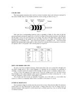
Table of Fluid Uses.
The following table is a brief summary of
the permissible uses of mineral-base hydraulic fluids.
15
AL0907
Table 1-1.
Uses of Mineral-Base Hydraulic Fluids.
Corrective Action Following Improper Servicing.
If a hydraulic
system or component is erroneously serviced with vegetable-base
fluid, the system must be drained immediately and then flushed with
lacquer thinner: military specification MIL-T-6094A. Following this,
the components of the system must be removed and disassembled to the
extent necessary to remove all seals.
The components are washed,
seals are replaced with new ones, and the system is reassembled for
return to operation.
HANDLING OF FLUIDS
Trouble-free operation of hydraulic systems depends largely on the
efforts made to ensure the use of pure hydraulic fluid in a clean
system.
Bulk containers of fluids must be carefully opened and
completely closed immediately after dispensing any fluid.
After
dispensing, unused fluid remaining in gallon and quart containers
must be disposed of according to TM 10-1101.
Dispensing equipment
must be absolutely clean
16
AL0907