Solar Guideline Jinkosolar_Kien Do Trung
Bạn đang xem bản rút gọn của tài liệu. Xem và tải ngay bản đầy đủ của tài liệu tại đây (3.5 MB, 48 trang )
Confidential
Solar system – Basic guideline
Customer-Oriented
Technology-Driven
Brand-Reliable
品质中心
Content
1
Forewords
2
Preparation
3
Design
4
Installation
5
Operation & Maintenance
Confidential
1. Forewords
The purchase and installation of a solar electric system start with plenty of research and planning. Even if you hire a solar
company or certified installer to do the work, your informed participation will ensure that quality products get installed at a
competitive price, with the right system size chosen and placed at an optimum orientation to the sun and finally, building a
strong, highly efficient solar power system which can generate power in a long term.
This guide introduces you to the basic steps of solar system implementation – focus on the components of a residential gridtied PV system. It walks you through the site assessment, system sizing, component selection, installation details and other steps
involved. For the Operation & Maintenance – it focuses on the larger scale solar projects.
Customer-Oriented
Technology-Driven
Brand-Reliable
Confidential
2. Preparation
2.1 Rule out any potential showstoppers / obstacles:
- House/roof-top/land ownership: A solar system need time to achieve payback and profit.
- Mechanical ability of the roof, land area compare with ability windstorm, meteorological and hydrological
characteristics of the area.
- Trees, tall buildings or other significant shade obstacles: To avoid any unexpected lost of power capacity, we
should make a careful survey and design.
- Power system / grid requirement for solar system tie-ins to the grid.
Customer-Oriented
Technology-Driven
Brand-Reliable
Confidential
2. Preparation
2.2 Review building, electrical, fire and other codes that apply to your PV installation:
- Local permitting
- Power grid interconnection
- Electrical codes
- Fire codes
- Safety regulations
Customer-Oriented
Technology-Driven
Brand-Reliable
Confidential
2. Preparation
2.3 Perform an energy audit and load analysis:
- Energy audits serve three basic objectives:
To find out how much solar power you need
To fulfill a key requirement of some tax credits, rebates and loans
To lower your monthly electricity bill by eliminating wasteful consumption
- You need to perform a load analysis for a grid-tied PV system if you plan to include battery back-up
Items
Capacity
(W)
Quantity
Hourly
Usage Daily
Daily consumption
Wh
Refrigerator
275
1
10h
2750
Fan
100
4
6h
2400
…
Customer-Oriented
Technology-Driven
Brand-Reliable
Note
Confidential
2. Preparation
2.4 Perform a site survey:
- The site survey scopes out the property to determine the
following:
To find out the best spot for a PV array
Determine square footage available for module placement
Realize shading obstructions (if any)
Checking status of the roof
Status and size of the home's main electric panel
Available locations for mounting electrical components
Customer-Oriented
Technology-Driven
Brand-Reliable
Confidential
2. Preparation
2.4 Perform a site survey:
- While on the roof, you or your contractor should make a quick sketch of the
area. Things to include:
overall roof material, conditions, dimensions, thickness, dimensions of the
rafters or beams...etc
slope angles (especially for the most southerly facing areas)
locations of the chimney and vents
available array spaces (including length and width)
compass orientation of the array spaces or roof slopes
thickness of the roof (i.e. the distance from the surface down to the rafter,
truss or beam)
tall trees or other obstructions on or near the property
Customer-Oriented
Technology-Driven
Brand-Reliable
Confidential
3. Design
3.1 Select System capacity and Main equipment:
Depends on your power demand (kWh) or your applicable
area (m2) , you should choose a fix capacity for your Solar
system
Base on the DC capacity , choose the type of module which will
be used for your system (for example if we need a 1000 watt
system, then that’s 10 x 100 watt panels or 5 x 200 watt panels)
Choosing main equipment: PV module and Inverter
High power rate: reduce the BOS cost, save the
land/rooftop area, O&M cost… thereby reduce LCOE,
higher IRR.
Durability: Using high quality BoM.
Reliability: Meet the testing requirement by 3rd party
Customer service – Reputation branding
Customer-Oriented
Technology-Driven
Brand-Reliable
Confidential
3. Design
3.2 System configuration:
There
are 03 types of system configuration, base on the types of Inverter used:
Micro inverter - the best solution for shading area and prevent mismatch losses, however, its cost
also the highest one apply for system has a small capacity (d)
The string inverter – often be used for residential rooftop system, serving self-powered demand
with small capacity (b)
We also have Multistring inverter - often be used for commercial system, medium capacity – often
under 1 MW (c)
Central inverter – for the utility project with large capacity. Central inverters are less expensive than
string overall for large utility-scale installations because fewer are required per site. But for smaller
utility-scale projects, multistring inverters could win out for their easier serviceability
In this slide talking about system design, we focus on the System using String inverter.
Array layout & String calculation: Incase you don’t use the Micro inverter, the array layout should be compatible
with the string calculation to minimize the number of DC cable required to use, thereby reducing the voltage drop on
cable and saving the materials needed. For example: If you make it 12 modules per string, the array layout should be
designed for 12 or 24 or 36 modules...
Customer-Oriented
Technology-Driven
Brand-Reliable
Confidential
3. Design
3.2 System configuration:
The smaller size of the maximum power point tracking (MPPT) zone: from a central inverter (E.g. 300kW), to
zone-level MPPT (E.g. 30kW), to string-level MPPT (E.g. 3kW), and finally module-level MPPT (E.g. 300W)
results in an improvement to the mismatch losses.
Customer-Oriented
Technology-Driven
Brand-Reliable
Confidential
3. Design
3.2 System configuration:
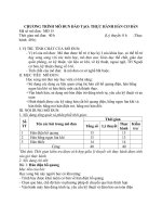
How many PV modules per string ?
Module maximum Open-Circuit voltage:
VDCmax MOD = Voc STC x [ 1 + (Temperature coefficient of Voc x ΔT)]
Module minimum MPP voltage:
VDCmin MOD = VMPP STC x [ 1 + (Temperature coefficient of Voc x ΔT)]
ΔT = Temperature expected - Standard test temperature (STC: 25°C)
Maximum number of modules per string
Nmax st = Vdc max Inv / VDCmax MOD ;
E.g. Calculation for VDCmax MOD of Cheetah
module HC 72M-V at lowest temperature –
assume at -10°C and highest temperature
70 °C
Minimum number of modules per string
VDCmax MOD = 49.8 x [1+(-0.28% x (-35))]
Nmin st = VDCMPP min Inv / VDCmin MOD ;
= 54.68 VDC (ΔT1 = -10-25 = -35 (°C ))
Number of PV Modules per String (Nst)
VDCmin MOD = 41.7 x [1+(-0.28% x 45)]
Nmin st ≤ Nst ≤ Nmax st ( Nst is an integer number)
= 36.45 VDC (ΔT2 = 70-25 = 45 (°C ))
Customer-Oriented
Technology-Driven
Brand-Reliable
Confidential
3. Design
3.2 System configuration:
How many strings ?
String number for system = System capacity (DC) / Nst
Oversize design: Oversizing a PV array, also referred to as under sizing a PV inverter, involves installing a PV array with a rated DC
power (STC) which is larger than an inverter’s rated AC output power (i.e. DC @ STC > AC). It can be a valuable tool for system
designers seeking to deliver a maximum amount of energy at a lowest possible specific cost.
Many people think DC/AC ratios of 1.1 are ideal, with 1.2 as slightly aggressive. Instead, design values of 1.2 often result in minimal
losses, while a 1.25 or 1.3 value can improve project economics, especially when a project size is constrained by the AC capacity.
Higher ratio will significant increase “clipping loss”
Simulation is carried out for 3 kW inverter at various overloading ratio by gradually increasing the DC power:
Customer-Oriented
Technology-Driven
Brand-Reliable
Confidential
3. Design
3.3 Select and sizing your PV array and modules:
After you have detail information of System capacity, PV
module type and Inverter type, let’s start doing the
design for the solar system.
To size an array, you need the following variables and
specs for mechanical works:
array area length and width (avoid shading)
module length and width (from catalogue,
datasheet)
module orientation (output cable length, cabling
method…)
hardware requirements (mounting racks, purlin,
clamp sizes…)
Customer-Oriented
Technology-Driven
Brand-Reliable
Confidential
3. Design
3.1 Select and sizing your PV array and modules:
Tilted Array Sizing:
Use PvSyst for optimization the module tilt and azimuth
Each row of modules must be separated by extra spacing.
Otherwise, when the sun is low in the sky, each row closer to the sun
will shade the one behind it.
Row Spacing = [Module height ÷ TAN(solar altitude angle)] X
COS(array azimuth)
o Height = Module Length X Sin(array tilt angle)
o Solar altitude angle: lowest sun altitude angle at either 9 AM or
3PM on winter solstice. In the Northern Hemisphere, this is the
December solstice (usually 21 or 22 December)
Experience equation
Latitude => Row spacing:
30° - - 2 X Module Height
35° - - 2.5 X Module Height
40° - - 3 X Module Height
45° - - 4 X Module Height
Pakistan 30.3753° N:
Row spacing = 2 x Module Height
Customer-Oriented
Technology-Driven
Brand-Reliable
Confidential
3. Design
3.2 Select and size your racking and mounts: A solar mount (or solar racking system) is the foundation that holds your
solar array in place. Mounts are used to attach solar panels to the roof, ground, or another surface on your property. With
proper installation, a sturdy mount secures your panels in harsh weather and protects your investment.
The solar mounting system basically divided into 03 types: Rooftop mounts, Ground mounts and Floating mounts
Quantity: Base on the Number of module and string.
Structure: Base on the design of tilt and row spacing, wind speed at the installed location, roof’s specifications…
Installation method (using bolt or clamp) which is suitable for difference module types (Monofacial or bifacial; Frame
or frameless…) NEVER FORGET THE GAP BETWEEN MODULES
Customer-Oriented
Technology-Driven
Brand-Reliable
Confidential
3. Design
3.4 Select and size the electrical components:
Once you finished the system configuration, you'll be ready to size wire, overcurrent devices (fuses and breakers), and conduit for the
circuit and chosen all your smaller electrical devices (i.e. combiner or junction box, disconnects, etc.). For residential solar electric
systems, always use copper wire. Aluminum wire is less expensive but breaks easily and corrodes. It's also less efficient in conducting
electricity.
Wire sizing calculations typically require the following information:
Module and Inverter spec sheets.
Array configuration (i.e. how many modules are wired in series and the number of series strings).
Whether or not you'll be using a junction or combiner box.
The placement, sizes and quantity of overcurrent devices in the circuit.
Hottest local temperature on record (or what's called the "2% Average" temperature for your region), as well as the coldest
you can expect.
Height of conduit running across the roof surface.
The types of wire you'll be using. (In home PV installations, the three most common are PV wire for the array (4mm2), bare
copper wire for the array ground wire)
Approximate wire travel distances.
Customer-Oriented
Technology-Driven
Brand-Reliable
Confidential
3. Design
3.4 Select and size the electrical components:
Combiner box (string inverter), Surge protection device, Fuse, Circuit Breaker:
Combiner box should be chosen base on the String configuration: How many module per string and how many string per box
The Surge protection device: Nominal voltage ≥ Nominal Inverter DC voltage.
Fuse: Base on PV module’s maximum seriesfuserating.
Circuit breaker: Base on the maximum working current of each line DC or AC
Customer-Oriented
Technology-Driven
Brand-Reliable
Confidential
4. Installation
4.1 Preparation for Installation works
Inspect, then store purchased components in a secure, dry place.
Read the installation guides, shop-drawing, engineering specs included with the modules, racks,
mounts, inverter and electrical devices or design-related documents
Devise a safety plan
Set up your staging area and logistics
Assemble the tools you'll need
Customer-Oriented
Technology-Driven
Brand-Reliable
Confidential
4. Installation
4.2 Measure out and install the mounting system (for the Ground mounting system – another document)
Before installing a solar array, be sure you understand how the roof is constructed. It's essential to secure your
mounts to the beams, trusses or rafters, which all refer to the 2 X 6 or 2 X 4 inch studs holding up the plywood
decking and other roofing material. These studs are normally spaced 24 inches apart, and have a relatively
narrow 1.5 inch thickness in which to drill into
Filling by waterproof silicon whenever hole penetrations are made into a roof
Customer-Oriented
Technology-Driven
Brand-Reliable
Confidential
4. Installation
4.3 Install the microinverters (if applicable), then the modules and grounding cable
If you're using microinverters for your array, you must install these on the rails prior to the modules.
Otherwise, you'll have to refer to your designer's electrical diagram to see how the modules will
connect together (and to the junction box) in a series/parallel configuration.
Normally, the grounding cable connect from Modules frame to the mounting system, then from
mounting system to Grounding pile, so before install the Module, you need to check the grounding
connection point.
Customer-Oriented
Technology-Driven
Brand-Reliable
Confidential
4. Installation
4.4 Mount your inverter, junction box and other electrical components
Based on your site survey and/or site drawing, you should know the location for the combiner box, inverter, and
any other components that are part of the solar electric system. This electrical equipment carries the wire
between the array and the home's main service panel. The junction box should be connected close to the array,
while the inverter and other components are usually placed on the ground, within proximity of the main panel.
Depending on their weight and dimensions, your electrical components may lay on the base or mount on a wall
Like any other electrical equipment, the inverter needs to be installed in a place that is safe, convenient for
operation and maintenance. The communication unit for the Inverter (if have) – also need to install.
Customer-Oriented
Technology-Driven
Brand-Reliable
Confidential
4. Installation
4.5 Cabling works and make all electrical connections
Cabling works includes connecting array cables and connect to combiner box, from combiner box to inside a central or string
inverter (if you use them), inside distribution boxes (if you use any) and most importantly inside the main service panel.
Remember these connections will have to remain snug for 25 years or more. Any loose ones can result in lost energy (at best) and
an electrical fire (at worst)
The on/off lever for disconnects, the central inverter and other components used in the circuit should likewise stay in the off
position until it's time to commission and test the solar electric system. Keep in mind that installed solar modules may be
transmitting DC current downstream (unless microinverters are used), even when the PV system is turned off.
All of the cable and connector should be marked with label and protected inside the conduit or trunking
Customer-Oriented
Technology-Driven
Brand-Reliable
Confidential
4. Installation
4.6 Test and inspect your solar system
Visual inspection – You could verify that:
The number of modules wired in series and parallel is correct.
The mounts are fastened securely to the roof and caulked.
All the bonding clips and jumpers, grounding wire and lug connections are tightly secured on the array.
All the module leads are snapped securely together and the array wiring is neatly fastened to the rails with
zip ties or clips.
The microinverter or combiner box is secured on the roof in an upright position, with no open holes, and
the conduit fastened.
All connections inside electrical enclosures (combiner box, disconnects, inverter, etc.) are complete and the
designated amount of torque applied to the screws.
The conduit is securely clamped to the walls and all fittings fastened or cemented as needed.
The inverter and other wall-mounted electrical components are mounted securely in place and an awning
constructed (if needed).
The required safety labels have been attached to the disconnects, inverter and at any other required
location.
Customer-Oriented
Technology-Driven
Brand-Reliable
Confidential
4. Installation
4.6 Test and inspect your solar system
Measurements & Electrical characteristic inspection for DC side:
The Polarity of all DC positive and negative wires
Open circuit voltage on each array string
Short circuit current on each array string
Voltage and current readings at the junction box or combiner, disconnects and inverter
System operating voltages and current
Wire resistance
Grounding connections
Once the DC side of the circuit is tested and the readings accurate, you can flip the DC disconnect switch to "On"
and take some more measurements. If everything looks good, you can turn on the inverter and see how it
responds. Note that all these tests are under no Load condition – Because you must have the inspection and
permit from Power grid management unit before connect your system with grid.
Customer-Oriented
Technology-Driven
Brand-Reliable