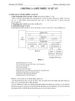
Bài giảng Vi xử lý: Chương 5 - Bùi Minh Thành (tt)
Bạn đang xem bản rút gọn của tài liệu. Xem và tải ngay bản đầy đủ của tài liệu tại đây (2.51 MB, 84 trang )
Chương 5
Thiết kế hệ vi xử lý
1
5.6 Giao tiếp bộ hiển thị (Display)
5.6.2 Giao tiếp với LCD
2
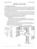
LCD controller
3
LCD Operation
LCD is gaining popular and replacing LEDs
(7-segment …), due to
1. declining price
2. the ability to display numbers, characters,
and graphics
3. relieving the CPU task by incorporating a
refreshing controller
4. ease of programming for characters and
graphics (OLED is the coming display)
4
LCD Pin Descriptions
14-pin LCD module is discussed here, table 12-1 lists pin’s function,
Fig 12-1 shows the pin positions for various LCDs
– Vcc, Vss provide +5V and ground
– Vee is used for contrast controlling
– RS (register select) is used to select the instruction command code
register (RS = 0) or data register (RS = 1)
– LCD command codes is listed at table 12-2
– R/W (read/write) allows user to write to (R/W = 0) or read from
(R/W = 1) information
– E (enable) latch information at data pins; when data is supplied to
data pins, a high-to-low pulse must be applied to this pin
– D0-D7 are the 8-bit data pins; send information to LCD (R/W = 0)
and read contents of LCD internal registers (R/W = 1)
– to display letters and numbers, ASCII codes are sent while RS = 1
5
6
7
Pin diagrams
– RS = 0, the command code register is selected, we can send instruction
to LCD to perform clear, shift, blink …
– when RS = 0, and R/W = 1, D7 is busy flag, when D7 = 0, LCD is ready
to receive new information; it is recommended to check the busy flag
before writing any data to the LCD
8
LCD Interfacing
• Liquid Crystal Displays (LCDs) have become a cheap and
easy way to display text for an embedded system
– Various configurations (1 line by 20 characters upto 8
lines by 80 characters).
• LCD needs a driving circuit to work.
• Driving circuit and LCD are often integrated into a single
chip Hitachi LM015 can display one line of 16 characters
• The display has one register into which commands are sent
and one register into which data to be displayed are sent
• Two registers are differentiated by the RS input
• Data lines (DB7-DB0) are used to transfer both commands
(clearing, cursor positioning, etc) and data (character to be
9
displayed)
Alphanumeric LCD Interfacing
Microcontroller
• Pinout
E
communications
bus
– 8 data pins D7:D0
R/W
RS
– RS: Data or Command
DB7–DB0
Register Select
8
LCD
controller
– R/W: Read or Write
LCD Module
– E: Enable (Latch data)
• RS – Register Select
– RS = 0 → Command Register
– RS = 1 → Data Register
• R/W = 0 → Write, R/W = 1 → Read
• E – Enable
– Used to latch the data present on the data pins.
• D0 – D7
– Bi-directional data/command pins.
10
– Alphanumeric characters are sent in ASCII format.
LCD Commands
• The LCD’s internal controller can accept several
commands and modify the display accordingly.
These commands would be things like:
– Clear screen
– Return home
– Decrement/Increment cursor
• After writing to the LCD, it takes some time for it
to complete its internal operations. During this
time, it will not accept any new commands or
data.
– We need to insert time delay between any two
commands or data sent to LCD
11
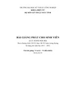
Interfacing LCD with 8051
8051
LM015
P3.4
RW
P3.5
E
P3.3
RS
P1.7-P1.0
D7-D0
12
Interfacing LCD with 8051
In main program:
...
MOV A, COMMAND
CALL CMD
CALL DELAY
MOV A, ANOTHER_CMD
CALL CMD
CALL DELAY
MOV A, #’A’
CALL DATA
CALL DELAY
MOV A, #’B’
CALL DATA
CALL DELAY ….
Command and Data Write Routines
DATA: MOV P1, A ; A is ascii data
SETB P3.3 ; RS=1 data
CLR P3.4 ; RW=0 for write
SETB P3.5 ; H->L pulse on E
CLR P3.5
RET
CMD: MOV
CLR
CLR
SETB
CLR
RET
P1, A
P3.3
P3.4
P3.5
P3.5
; A has the cmd word
; RS=0 for cmd
; RW=0 for write
; H->L pulse on E
13
14
15
16
17
LCD
18
LCD Timing
19
20
21
Stepper Motors
• more accurately controlled than a normal motor
allowing fractional turns or n revolutions to be
easily done
• low speed, and lower torque than a comparable
D.C. motor
• useful for precise positioning for robotics
• Servomotors require a position feedback signal
for control
22
Stepper Motor Diagram
23
Stepper Motor Step Angles
24
Terminology
• Steps per second, RPM
– SPS = (RPM * SPR) /60
• Number of teeth
• 4-step, wave drive 4-step, 8-step
• Motor speed (SPS)
• Holding torque
25