Analyzing the causes of strong seepage on xahuong dam and proposing solutions for handling master thesis major sustainble hydraulic structures coastal engineering and management code 62 58 02 0
Bạn đang xem bản rút gọn của tài liệu. Xem và tải ngay bản đầy đủ của tài liệu tại đây (3.14 MB, 79 trang )
THUY LOI UNIVERSITY & UNIVERSITY OF LIEGE
FACULTY OF CIVIL ENGINEERING
Presented by
MAI THI NGAT
ANALYZING THE CAUSES OF STRONG SEEPAGE
ON XAHUONG DAM AND PROPOSING SOLUTIONS
FOR HANDLING
Major :
Sustainable Hydraulic Structures
Student ID #
148ULG09
MASTER THESIS
Supervisor
: Dr. HO SY TAM
- Thuy Loi University
Co-supervisor : Prof. RADU SARGHIUTA - University of Liege
Ha Noi, 2016
MASTER THESIS
SUSTAINABLE HYDRAULIC STRUTURES
REASSURANCES
NAME: MAI THI NGAT
Major: Sustainable Hydraulic structure
Student Number: 148ULG09
I hereby declare that I am the person who conducted this master thesis under the
guidance of Dr. Ho Sy Tam and Prof.Radu Sarghiuta with the research topic in the
thesis “Analyzing the causes of strong seepage on XaHuong dam and proposing the
solution for handling”.
This is a new research topic which does not overlap with any dissertation before, so
there is no copy of any public dissertation. The contents of the thesis are presented in
accordance with regulations; the data resources and materials used in research are
quoted sources.
If there is any problem with the contents of this thesis, I would like to take full
responsibility as prescribed.
SIGN
MAI THI NGAT
MaiThiNgat
Supervisor: Dr. Ho Sy Tam
Co-Supervisor: Prof Radu Sarghiuta
MASTER THESIS
SUSTAINABLE HYDRAULIC STRUTURES
ACKNOWLEDGEMENTS
Master Thesis in major of sustainable hydraulic structure “Analyzing the causes
of strong seepage on XaHuong dam and proposing the solution for handling” was
completed in August, 2016
In the process of implementation of the thesis, I always get the encouragement
and devoted directions from my instructors _ Dr. Ho Sy Tam and Prof. Radu
Sarghiuta. I am really grateful for their invaluable help.
I also would like to express our sincere thanks to all of my teachers in
Sustainable Hydraulic structure Master course at Thuy Loi University, along with
professors from University of Liege had imparted valuable specialized knowledge for
me so that i can get this result.
Finally, I sincerely thank my family, my friends, and especially my classmates
who had exchanged enthusiastically, contributed and encouraged me to complete this
thesis.
Sincerely
SIGN
MAI THI NGAT
MaiThiNgat
Supervisor: Dr. Ho Sy Tam
Co-Supervisor: Prof Radu Sarghiuta
MASTER THESIS
SUSTAINABLE HYDRAULIC STRUTURES
CATEGORY
PREMISE ................................................................................ 1
1.1 THE URGENCY OF THE PROJECT ..................................................................... 1
1.2 RESEARCH OBJECTIVES ..................................................................................... 2
1.3 METHODOLOGY TO STUDY THE SUBJECT .................................................... 3
1.4 RESEARCH SCOPE OF THE STUDY ................................................................... 3
CHAPTER 1. GENERAL INTRODUCTION...................... 4
1.1 INTRODUCTION OF THE PROJECT ................................................................... 4
1.1.1 Location of Project area ................................................................................. 4
1.1.2 Topographical and geomorphological conditions ......................................... 4
1.1.3 Geological features ........................................................................................ 5
1.1.4 XaHuong reservoir ......................................................................................... 6
1.1.5 XaHuong Dam ............................................................................................. 10
1.1.5.1 Dam crest ................................................................................................... 10
1.1.5.2 Upstream dam slope .................................................................................. 11
1.1.5.3 Downstream dam slope ............................................................................. 12
1.2 SEEPAGE PROBLEM TO XAHUONG DAM ..................................................... 13
1.3 STUDIES ON SEEPAGE INSTABILITY THROUGH EARTH DAM ............... 16
1.3.1 Seepage flow ................................................................................................ 16
1.3.1.1 Causes of permeability .............................................................................. 17
1.3.1.2 Basic principle of seepage flow ................................................................. 18
1.3.1.3 Hydraulic gradient ..................................................................................... 19
1.3.1.4 Darcy law ................................................................................................... 19
1.3.1.5 Hydraulic conductivity .............................................................................. 21
1.3.1.6 Basic principle of seepage line .................................................................. 22
1.3.1.7 Permeable basic equation .......................................................................... 23
1.3.1.8 Planar permeable equation......................................................................... 24
1.3.2 Calculation of perfect anisotropy................................................................. 26
MaiThiNgat
Supervisor: Dr. Ho Sy Tam
Co-Supervisor: Prof Radu Sarghiuta
MASTER THESIS
SUSTAINABLE HYDRAULIC STRUTURES
1.3.2.1 Definition ................................................................................................... 26
1.3.2.2 Analysis about cause of permeability ........................................................ 30
CHAPTER 2: STUDY ABOUT CAUSES MAKING
SEEPAGE INSTABILITY THROUGH THE BODY OF
XA HUONG DAM ................................................................ 33
2.1 INTRODUCTION ABOUT CALCULATION SOFTWARE ............................... 33
2.1.1 Description ................................................................................................... 33
2.1.2 Steps to calculate ......................................................................................... 35
2.2 CALCULATION .................................................................................................... 40
2.2.1 Case 1: Normal working filter layer ............................................................ 42
2.2.2 Case 2: Clogged filter layer ......................................................................... 44
2.2.3 Case 3: Effects of anisotropic permeability ................................................. 46
2.2.4 Case 4: Effect of Anisotropy interlayer ....................................................... 52
CHAPTER 3: SEEPAGE TREATMENT SOLUTIONS .. 60
3.1 PROPOSED SOLUTION ....................................................................................... 60
3.1.1 Solution for case 3: Effect of anisotropic permeability ............................... 60
3.1.2 Solution for case 4: effect of anisotropic interlayer ..................................... 64
3.2 ASSESSMENTS ABOUT RESULTS ................................................................... 67
CHAPTER 4: CONCLUSION & RECOMMENDATION 68
REFFERENCES ................................................................... 70
MaiThiNgat
Supervisor: Dr. Ho Sy Tam
Co-Supervisor: Prof Radu Sarghiuta
MASTER THESIS
SUSTAINABLE HYDRAULIC STRUTURES
LIST OF FIGURE
Figure 1- 1: Location of XaHuong reservoir ensembles .................................................4
Figure 1- 2: XaHuong reservoir......................................................................................7
Figure 1- 3: Upstream view of XaHuong Dam .............................................................10
Figure 1- 4: Dam crest from the right abutment ...........................................................10
Figure 1- 5: Dam crest from the left abutment .............................................................10
Figure 1- 6: Crest of parapet wall ................................................................................11
Figure 1- 7: Foot of parapet wall..................................................................................11
Figure 1- 8: Dam slope in the left abutment .................................................................12
Figure 1- 9: Dam slope in the right abutment ...............................................................12
Figure 1- 10: Overall downstream dam slope ..............................................................13
Figure 1- 11: Dam slope m = 2.5, from elevation of +83.0m to dam crest ..................13
Figure 1- 12: The first dam berm at elevation of +83.0 m ...........................................13
Figure 1- 13: Dam slope m = 3.0 from elevation of +71.5 to +83.0 ............................13
Figure 1- 14: Handling the seepage of dam slope from elevation +71.5 to +83.0 ......15
Figure 1- 15: Concentrated rocks for seepage drainage on slope................................15
Figure 1- 16: Seepage drainage on berm at elevation +71.5 .......................................16
Figure 1- 17: Cross-section of dam...............................................................................26
Figure 1- 18: Transformation for Anisotropic Conditions ...........................................28
Figure 1- 19: Effect of Anisotropy on Seepage through an Earth Dam .......................29
Figure 2- 1: Geoslope software interface .....................................................................33
Figure 2- 2: Creating analysis properties .....................................................................35
Figure 2- 3: Importing region from AutoCAD program ...............................................36
Figure 2- 4: Defining material layers ...........................................................................36
Figure 2- 5:Defining hydraulic boundary conditions ...................................................37
Figure 2- 6: Drawing material layers ...........................................................................37
Figure 2- 7: Drawing boundary conditions ..................................................................38
Figure 2- 8: Solving data ..............................................................................................38
Figure 2- 9: Displaying results .....................................................................................39
MaiThiNgat
Supervisor: Dr. Ho Sy Tam
Co-Supervisor: Prof Radu Sarghiuta
MASTER THESIS
SUSTAINABLE HYDRAULIC STRUTURES
Figure 2- 10: Viewing report ........................................................................................39
Figure 2- 11: Drawing permeable grid and sliding center ...........................................40
Figure 2- 12: Contributed material layers ....................................................................40
Figure 2- 13: Calculated diagram of seepage stability for case 1 ................................42
Figure 2- 14: Seepage calculation results for case 1 ....................................................42
Figure 2- 15: Calculated result of slope slide stability (Normal load combination) ....43
Figure 2- 16: Calculated diagram of seepage stability for case 2 ................................44
Figure 2- 17: Seepage calculation results for case 2 ....................................................44
Figure 2- 18: Calculated result of slope slide stability (Normal load combination) ....45
Figure 2- 19: Calculated diagram of seepage stability for case 3 ................................46
Figure 2- 20: Calculated diagram of slope stability (Normal load combination) ........46
Figure 2- 21: Seepage calculation results for case 3 (ratio=7) ...................................47
Figure 2- 22: Calculated result of slope slide stability (Normal load combination) ....47
Figure 2- 23: Seepage calculation results for case 3(ratio=10) ..................................48
Figure 2- 24: Calculated result of slope slide stability (Normal load combination) ....48
Figure 2- 25: Seepage calculation results for case3(ratio=14) ...................................49
Figure 2- 26: Calculated result of slope slide stability (Normal load combination) ....49
Figure 2- 27: Seepage calculation results for case3(ratio=20) ...................................50
Figure 2- 28: Calculated result of slope slide stability (Normal load combination) ....50
Figure 2- 29: Contributed material layers ....................................................................52
Figure 2- 30: Calculated diagram of seepage stability for Z=70m ..............................53
Figure 2- 31: Seepage calculation results for Z=70m ..................................................53
Figure 2- 32: Calculated result of slope slide stability (Normal load combination) ....54
Figure 2- 33: Calculated diagram for Z=80m ..............................................................55
Figure 2- 34: Seepage calculation results for Z=80m ..................................................55
Figure 2- 35: Calculated result of slope slide stability (Normal load combination) ....56
Figure 2- 36: Calculated diagram for Z=84m ..............................................................57
Figure 2- 37: Seepage calculation results for Z=84m ..................................................57
Figure 2- 38: Calculated result of slope slide stability (Normal load combination) ....58
Figure 3- 1: Contributed material layers ......................................................................61
MaiThiNgat
Supervisor: Dr. Ho Sy Tam
Co-Supervisor: Prof Radu Sarghiuta
MASTER THESIS
SUSTAINABLE HYDRAULIC STRUTURES
Figure 3- 2: Calculated diagram of seepage stability ..................................................61
Figure 3- 3: Seepage calculation result ........................................................................62
Figure 3- 4: Calculated diagram of slople stability (Normal load combination) .........62
Figure 3- 5: Calculated result of slope slide stability (Normal load combination) ......63
Figure 3- 6: Contributed material layers ......................................................................64
Figure 3- 7: Calculated diagram of seepage stability ..................................................65
Figure 3- 8: Seepage calculation result ........................................................................65
Figure 3- 9: Calculated diagram of slople stability (Normal load combination) .........66
Figure 3- 10: Calculated result of slope slide stability (Normal load combination) ....66
MaiThiNgat
Supervisor: Dr. Ho Sy Tam
Co-Supervisor: Prof Radu Sarghiuta
MASTER THESIS
SUSTAINABLE HYDRAULIC STRUTURES
LIST OF TABLE
Table 2. 1: Mechanical and physical indicators of fill-soil for dam body and
foundation ......................................................................................................................41
Table 2. 2: Output data of case 3 ..................................................................................51
Table 2. 3: Output data of case 4 ..................................................................................58
Table 3. 1: Output data .................................................................................................67
MaiThiNgat
Supervisor: Dr. Ho Sy Tam
Co-Supervisor: Prof Radu Sarghiuta
MASTER THESIS
SUSTAINABLE HYDRAULIC STRUTURES
PREMISE
1.1 THE URGENCY OF THE PROJECT
Earth dam is a type of dam built by the existing soils in the building region such
as clay, clayed , sandy loam, sand, gravel, cobbles ... Earth dam has simple and stable
structure, capable of highly mechanized during the construction and in most cases.
Earth dam is widely applied in most countries. This type of dam has advantage of
using local materials which are available at construction area, so it has cheaper
construction costs comparing to other types of the same scale dams. However, earth
dam also contains many risks, easy to occur unsafe incident to dams if the designing
work and construction does not guarantee the requirements such as foundation
treatment, dam structure selection, appropriate material planning for fill soil of an
embankment dam as well as densification ensure uniformity and tightness of each fill
layer. According to statistic, permeability occupies high rate in the cause of making
reservoir built with local materials unsafe.
In our country, most of the earth dams are made of homogeneous soil. When
water level rise and lowered erratically, it will destabilize the slope of dam, leading to
sliding, subsidence, local erosion...
Therefore, the calculation of stability mode for the earth dam is very
important… Usually we only calculate permeability in homogeneous environments.
Concept of permeability of earth dams in case of homogeneous soil often do not lead
to significant errors comparing to fact. If the dam body or the dam's waterproofing
parts are constructed with materials relatively homogeneous with small value of
heterogeneous coefficient then we can solve the seepage problem with homogeneous
environment.
Moreover, beside case of normal calculation (isotropic environment), we must
pay attention to the heterogeneity of the material (anisotropy of permeability). The
inhomogeneous - anisotropic usually occur because of earth dam construction
MaiThiNgat
1
Supervisor: Dr. Ho Sy Tam
Co-Supervisor: Prof Radu Sarghiuta
MASTER THESIS
SUSTAINABLE HYDRAULIC STRUTURES
technology with horizontal soil layers, having the difference in permeability
coefficient between horizontal and vertical layers (ktx,kty); whereas: ktx, kty are
permeability coefficients of horizontal x and vertical y.
In fact, we often see the type of land with permeable foundation, soil
foundation and fill soil of dam includes many different layers. The problems of this
type are complicated, because we have to mention the environment with multiple
layers as well as complex boundary conditions. The seepage problem solutions that we
had learned only approximate and simple.
When calculating permeability, we must analyze the viability of the material
with anisotropic permeability coefficient with different values to take measures to
overcome the adverse consequences of distortion repellent.
Recently, there are 2 methods to calculate permeability: permeability
calculation by analytical method (straight-line rate method of Lence - American
engineer, published in 1934) and by numerical model method (using software SEEP /
W version in 2007 by GEO-SLOPE International, Ltd. Development Canada).
Today, beside the the significant progress in using numerical methods in
particular and the strong development of modern technology in general, we can solve
the permeability problem more quickly and easily... In my thesis which is “Analyzing
the causes of strong seepage on XaHuong dam and proposing the solution for
handling”, the auther will apply calculation software namely GEOSLOPE to calculate
the anisotropic permeability of XaHuong dam.
1.2 RESEARCH OBJECTIVES
The main purposes of this research are to study the causes of the permeability
phenomenon occuring inside XaHuong dam body and based on basic theoretical to
calculate and propose solutions to handle this problem.
MaiThiNgat
2
Supervisor: Dr. Ho Sy Tam
Co-Supervisor: Prof Radu Sarghiuta
MASTER THESIS
SUSTAINABLE HYDRAULIC STRUTURES
1.3 METHODOLOGY TO STUDY THE SUBJECT
Using Geoslope software (Seep/W and Slope/W) to calculate seepage and slope
stability of dam in different cases, especially in two cases: Anisotropic seepage and
anisotropic interlayer, based on calculations results, comparing and assessing effect of
seepage instability to XaHuong dam; then analyzing and giving the best waterproofing
solutions for seepage problem of XaHuong dam.
1.4 RESEARCH SCOPE OF THE STUDY
In this research, I just focus on study application of GEO-SLOPE to calculate
stability for XaHuong earth dam in isotropic and anisotropic cases.
MaiThiNgat
3
Supervisor: Dr. Ho Sy Tam
Co-Supervisor: Prof Radu Sarghiuta
MASTER THESIS
SUSTAINABLE HYDRAULIC STRUTURES
CHAPTER 1. GENERAL INTRODUCTION
1.1 INTRODUCTION OF THE PROJECT
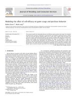
1.1.1 Location of Project area
Is managed by Limited Company MTV Thuy Loi Tam Dao, Xa Huong
reservoir is located in Buffalo Valley, at the foot of Tam Dao moutain of Xa Huong
village (Minh Quang, Tam Dao, Vinh Phuc), away about 2 km from the National
Highway 2B at Km13 and about 15 km North East to Vinh Yen city [1].
Management
house
Water intake
culvert
Management
road
Earth dam
Flood discharge
spillway
Figure 1- 1: Location of XaHuong reservoir ensembles
1.1.2 Topographical and geomorphological conditions
Headwork area of XaHuong dam cut across a narrow valley - in the foot of Tam
Dao mountain (Vinh Phuc). With a slope towards the northeast – southwest, the main
river originates from the Tam Dao mountain (Tam Dao has mountain side with steep
slopes and high level of coverage) [1].
MaiThiNgat
4
Supervisor: Dr. Ho Sy Tam
Co-Supervisor: Prof Radu Sarghiuta
MASTER THESIS
SUSTAINABLE HYDRAULIC STRUTURES
1.1.3 Geological features
In the hydrological report of the Company Consulting and Technology Transfer
(in 2009) , the characteristics of natural features, climate as well as meteorology in
area of work was described as following:
There are 3 pits (symbol KM1 - KM3) had dilled at the dam route area,
wheareas:
- The borehole KM1 with a depth of 30.5 m was laid out on the dam berm at
elevation +83.0 m
- The boreholes Km2 and KM3 with a depth of 20 m was laidout on the berm at
elevation +71.5 m
Besides, drill holes are arranged to form the vertical and horizontal geologic
cross sections . Stratigraphic layers are described from top to bottom [1]:
- Dam fill - soil (symbolized A): reddish brown clay, gray, hard plastic to the
semi-rigid state, tight texture, stones mingled with small debris with thickness
decreasing towards the foot of the dam, the bottom layer at elevation +59.0 m.
At layer A conducted the experiment pouring water into borehole KM1, KM2
and KM3, with hydraulic conductivity K = 10-4 to 10-5 cm/s.
- Stone weathered completely -Tropical IA1 (symbol 2): clay mingled stone
debris which have still not weathered all, has brown red, white and semi-rigid
state. Layer 2 is present in three drilled holes with relatively uniform thickness,
approximately 3-4 m. At group of completely weathered rock, conducted
pouring water testing at Km1 and KM3, hydraulic conductivity was 2 × 10⁻⁵
m/s.
- Stone weathering light, fresh - Tropical IIB (symbol 3): underlying layer 2,
slightly discolored rocks, closed cracks, unbroken peeled drilling; very rigid,
MaiThiNgat
5
Supervisor: Dr. Ho Sy Tam
Co-Supervisor: Prof Radu Sarghiuta
MASTER THESIS
SUSTAINABLE HYDRAULIC STRUTURES
hard to break by hammer pounding. At moderate weathered group, conducted
pouring water at KM2, hydraulic conductivity is K = 2×10⁻⁵ m/s.
Based on the design documents of the Corporation Construction Consulting
VN-2013 about urgent waterproofing handling for Xa Huong dam body; we can drawn
the following assessments about geological conditions:
- From the results of the survey, the dam fill - soil had uneven compaction factor
due to distribution area and the height of the dam. From elevation +84.8 m
+80.5 m to the dam surface, filled Soil have better compacted factor, but there
are some places still have unsatisfactory compacted factor. Or we can say that,
filled soil quality is not satisfactory if comparing with the standard design of the
dam and earth dam construction in past as well as present (with the required
density Kc 0.95).
- According the the previous design, the dam was remolded homogenate, but the
actual check shown that filled soil of the dam body is not homogenate, reflected
by the results of experiments undisturbed soil samples
- Results geophysical survey by electrical symmetry depth also showed dam
body locally have voids (in the dry part has high resistivity = 2000 2500
m and more hydrated wet section has electricity low resistivity = 50 100
m. These positions can be the termite nest or fill soil has not been compacted.
1.1.4 XaHuong reservoir
XaHuong reservoir is located in Minh Quang commune, Tam Dao district, Vinh
Phuc province.
This is a quite deep lake, about 83 hectares wide, with many large niche
through the woods, was started construction in 1977 and was completed and put into
operation in 1984 with a capacity of over 12 million m3 of water, enough irrigation
MaiThiNgat
6
Supervisor: Dr. Ho Sy Tam
Co-Supervisor: Prof Radu Sarghiuta
MASTER THESIS
SUSTAINABLE HYDRAULIC STRUTURES
water for 1,850 hectares farmland of the three districts Tam Dao, Binh Xuyen and Tam
Duong. (Wikipedia, the free encyclopedia)
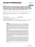
Figure 1- 2: XaHuong reservoir
The crest elevation of XaHuong dam is +94m, dam toe elevation is +50m and
the largest dam height is 41m. This reservoir is also put on the list of important
projects of the Ministry of Agriculture and Rural Development.
Being one of the reservoirs with a large dam height and volume in VinhPhuc
province, XaHuong reservoir plays an important role in the development of the
economy, especially the development of the province. After being put into operation,
so far, XaHuong reservoir has undergone some major repairs in order to improve the
level of safety of the construction in the years 1991, 2009 and 2013, 2015.
MAJOR SPECIFICATIONS:
Reservoir:
- Construction grade: I
- Design flood frequency: PTK = 2%
MaiThiNgat
7
Supervisor: Dr. Ho Sy Tam
Co-Supervisor: Prof Radu Sarghiuta
MASTER THESIS
SUSTAINABLE HYDRAULIC STRUTURES
- Irrigation ensure percentage: P = 75%
- Flood control regulation: Year
- Normal Water level ( NWL): 91.5m
- Hi-rising water level (CFL): 93.5m
- Dead water level (DWL): 66 m
- Basin area : FLV = 24km2
- Reservoir’s surface area corresponding to NWL: 0.853km2
- Reservoir’s surface area corresponding to DWL : 0.15km2
- Reservoir’s storage corresponding to CFL: 15.8×10⁶m3
- Effective storage: 13.43×10⁶m3
- Dead storage : 0.7×10⁶m3
Headworks clusters
Hydraulic works system of Xa Huong reservoir include items such as: homogeneous
soil; spillway in left abutment of dam; offtake culvert in right abutment of dam ;
systems of managed road from inter-village roads and manager house.
Earth dam
Xa Huong dam is homogeneous dam with a height of about 41m, 252m length
and 5m crest width ; the crest elevation of earth dam is + 94m, the crest elevation
MaiThiNgat
8
Supervisor: Dr. Ho Sy Tam
Co-Supervisor: Prof Radu Sarghiuta
MASTER THESIS
SUSTAINABLE HYDRAULIC STRUTURES
of breakwater wall is + 95m. Upstream slope has slope coefficient are 4.5 ; 3.5
and 2.75, which are separated by berms at the elevations +64m; +70m, +84m,
+94m; The upstream slope with slope coefficient of 2.5, 3.0 and 3.5, are
separated by berm at elevations +83m; +71.5m; and +60m.
Culvert
Offtake culvert is arranged at the dam right abutment, with reinforced concrete
structure size b × h = 1 × 1.4 m. The elevation of the sewer inlet is +64.0 m.
Length of culvert L = 200 m. Form of culvert is non-pressure box (RC box
culvert), using reinforced concrete material; steel valve gate operated by V30),
and is regulated by flat valve placed in the culvert tower in upstream. Design
flow Q = 2.1 m3/s and culvert slope i = 5%.
Main spillway
Spillway of XaHuong reservoir is form of Broad-crested weir , is regulated by
Arch-shaped valve-gate and arranged in left abutment of dam. Size of valves is
B× h = 10 × 4 m, the elevation of spillway threshold is +87.5 m. The width of
water slope is Bd = 10m. The entrance of spillway is form of gradually
narrowing, serial form following spillway are water slope - chute and energy
dissipation, whereas the design discharge = 259m3/s and the length of Chute L =
154.6m.
Management house
MaiThiNgat
9
Supervisor: Dr. Ho Sy Tam
Co-Supervisor: Prof Radu Sarghiuta
MASTER THESIS
SUSTAINABLE HYDRAULIC STRUTURES
1.1.5 XaHuong Dam
Figure 1- 3: Upstream view of XaHuong Dam
1.1.5.1
Dam crest
Figure 1- 4: Dam crest from the right
Figure 1- 5: Dam crest from the left
abutment
abutment
MaiThiNgat
10
Supervisor: Dr. Ho Sy Tam
Co-Supervisor: Prof Radu Sarghiuta
MASTER THESIS
SUSTAINABLE HYDRAULIC STRUTURES
Figure 1- 6: Crest of parapet wall
Figure 1- 7: Foot of parapet wall
(Images taken from the safety report of XaHuong Dam [1])
With the height of about 41m, the homogeneous dam XaHuong has dam crest
which is 252m length, 5m width. The earth dam crest has elevation of + 94m and
parapet wall has elevation of + 95m.
Structured by crushed gravel, due to the impact of natural conditions, dam crest
is no longer being flat as the original state (Figure 1- 4). In the top of the dam crest, a
stone parapet wall was built with the height of 1m. In some locations at the crest and
foot of this wall, the external concrete mortar layer is peeled (Figure 1- 6 and Figure 17).
The drainage ditch behind the parapet wall was strongly filled so many sections
no longer have ability of drainage (Figure 1.6).
Besides, there is no lighting equipment in the dam crest
1.1.5.2
Upstream dam slope
Slope coefficient of upstream slopes are m = 4.5; 3.5 and 2.75, which are
separated by the dam berms at elevations of +64.0; +70.0; +84.0 and 94.0 (Figure 1- 8
and Figure 1- 9). The slope is protected by stone riprap on ballast and gravel layer to
prevent wave action. The dam slope is flat and has no phenomenon of disproportion,
peeling stone or uneven.
MaiThiNgat
11
Supervisor: Dr. Ho Sy Tam
Co-Supervisor: Prof Radu Sarghiuta
MASTER THESIS
SUSTAINABLE HYDRAULIC STRUTURES
Figure 1- 8: Dam slope in the left
Figure 1- 9: Dam slope in the right
abutment
abutment
(Images taken from the safety report of XaHuong Dam [1])
1.1.5.3
Downstream dam slope
Downstream slope has slope coefficient m = 2.5; 3.0 and 3.5, are separated by
the dam berms at elevations of +83m; +71.5m; and +60m (Figure 1-12 & Figure 1-13)
[1].
Due to the relatively flat of dam slope, the grass grows evenly; leading to the
downstream slope is protected by grass.
At the present time, there are some problems to the surface drainage ditch
which is executed by stone, lied on the dam berm, at the dam foot and along the slope.
Some positions is been peeling and some are covered by grass (Figure 1- 10 to Figure
1.13).
Besides, drainage ditch at the foot of prismatic drainage is made of soil.
Monitoring the seepage flow becomes difficult because a part of water from the intake
culvert flow back into this ditch, however we can’t distinct whether water in this ditch
is permeable water or water poured into this ditch from the downstream side of
culvert.
MaiThiNgat
12
Supervisor: Dr. Ho Sy Tam
Co-Supervisor: Prof Radu Sarghiuta
MASTER THESIS
SUSTAINABLE HYDRAULIC STRUTURES
Because of working time and especially by seepage water through the dam
body, some locations of dam berm are deformed.
At the prismatic drainage in the downstream, a flow appears from this prismatic
to drainage ditch.
Figure 1- 10: Overall downstream dam
Figure 1- 11: Dam slope m = 2.5, from
slope
elevation of +83.0m to dam crest
Figure 1- 12: The first dam berm at
Figure 1- 13: Dam slope m = 3.0 from
elevation of +83.0 m
elevation of +71.5 to +83.0
(Images taken from the safety report of XaHuong Dam [1])
1.2 SEEPAGE PROBLEM TO XAHUONG DAM
Was the 2nd highest earth dam in Vietnam, XaHuong reservoir was constructed
in 1977 and in 1984 it was put into usage. After nearly 40 years of exploitation, some
works and items have been repaired and upgraded several times.
MaiThiNgat
13
Supervisor: Dr. Ho Sy Tam
Co-Supervisor: Prof Radu Sarghiuta
MASTER THESIS
SUSTAINABLE HYDRAULIC STRUTURES
In Safety report of XaHuong dam, the monitoring phenomenon in reality are
described as follow: in September of 1990, when the reservoir capacity reached at
elevation +86.0 m, the permeable water appeared and leaked more toward the
downstream slope from elevation +77.0 m and +74.0 m. Therefore, in 1991 The
Ministry of Water Resources (former) had handled waterproof by drilling grouting of
cement and clay into the dam body and simultaneously, upstream slope was paved by
stone quarry from elevation +84.0 m to +94.0 m and cobblestone chit from elevation
+84.0 m to +64.0 m.
However, after waterproof handling, the permeable phenomena still appears at
downstream slope from elevation +74.0 m to +85.0 m (including the water intake
culvert).
This safety report also records after the storm No. 5 in 2012 when the water
level raised to the designed elevation +91.50m, strong seepage phenomenon occurred
at downstream slope of earth dam, leading to drenched dam slope and creating flow on
drainage trench, then the dam body had signs of cracks, hollow inside. This is not
allowed in the dam safety regulations, particularly for earth dam as the dam XaHuong.
Besides, the dam has not built the safety system yet when exceeding the flood design
level or historical flood.
In early 2015, the next time of drilling jet grouting was conducted. The range
was around the culvert with a length of about 75 m, 0.5 m from the bottom of drain to
the elevation +71.25 m.
At the time of the survey, the October of 2015, the water level in the reservoir
was +84.55 m, the downstream slope completely dried, in stark contrast to time before
the waterproofing handling. As reported by the management unit, before the
waterproofing handling, when the level of water in the reservoir rose up to the same
elevation, the permeability flow appeared at downstream at different positions,
forming the seepage dumps. Management unit had to use stone quarry as the drainage
ditch of seepage and accumulated stone quarry on berm to handle permeability
frequently.
MaiThiNgat
14
Supervisor: Dr. Ho Sy Tam
Co-Supervisor: Prof Radu Sarghiuta
MASTER THESIS
SUSTAINABLE HYDRAULIC STRUTURES
Because of termites nesting phenomenon so in 2008, the dam was processed by
drilling termite spraying.
Figure 1- 14: Handling the seepage of dam slope from elevation +71.5 to +83.0
Figure 1- 15: Concentrated rocks for seepage drainage on slope
MaiThiNgat
15
Supervisor: Dr. Ho Sy Tam
Co-Supervisor: Prof Radu Sarghiuta
MASTER THESIS
SUSTAINABLE HYDRAULIC STRUTURES
Figure 1- 16: Seepage drainage on berm at elevation +71.5
With the complicated movements of weather situations and the risk of dam
failure, the need of finding out the causes of strong seepage on the dam body and
finding out solutions to that problem is extremely urgent to ensure the safety of
XaHuong dam.
(Source: Data and images taken from Safety report of XaHuong dam [1])
1.3 STUDIES ON SEEPAGE INSTABILITY THROUGH EARTH DAM
1.3.1 Seepage flow
Research purposes about seepage of the earth dam are to address the following
issues:
-
Identifying the discharge of seepage flow through the dam, foundation and
shore to assess water loss in calculations and balance the reservoir.
Simultaneously, based on the basis of this calculation, we will determine the
form of waterproofing for foundation and dam body.
MaiThiNgat
16
Supervisor: Dr. Ho Sy Tam
Co-Supervisor: Prof Radu Sarghiuta