Ebook Fundamentals of spun yarn technology: Part 2
Bạn đang xem bản rút gọn của tài liệu. Xem và tải ngay bản đầy đủ của tài liệu tại đây (540.55 KB, 20 trang )
<span class='text_page_counter'>(1)</span><div class='page_container' data-page=1>
Y
arn Formation Structure
and Properties
<b>6.1</b> <b>SPINNING SYSTEMS</b>
There is an extensive range of different spinning systems, not all of which are in
wide commercial use; many are still experimental or, having reached the commercial
stage, have been withdrawn from the market. A classification of the better known
spinning systems is given Table 6.1, in which the various techniques are grouped
according to five basic methods. In the first section of this chapter, we will consider
the fundamental principles of these listed spinning systems. In the sections that
follow, we will deal with the yarn structure and properties of only those that still
have commercial significance. Often, two or more yarns are twisted together to
improve yarn properties or to overcome subsequent processing difficulties in, for
example, weaving and knitting. The operating principles of the more common plying
systems will also be described in this section.
The conventional ring spinning technique is currently the most widely used,
accounting for an estimated 90% of the world market for spinning machines. The
remaining systems in Table 6.1 are often referred to as <i>unconventional spinning </i>
<i>processes </i>and, of these, rotor spinning has the largest market share. The more
knowledgeable reader will notice that mule and cap spinning have been omitted.
Although in commercial use, these two processes are very dated traditional systems,
limited to a very small market segment and well described elsewhere.1,2
Important aspects of any spinning system are the fiber types that can be spun,
the count range, the economics of the process, and — very importantly — the
suitability of the resulting yarn structure to a wide range of end uses. Except for the
twistless-felting technique, all of the systems listed in Table 6.1 will spin man-made
fibers, but because of processing difficulties and/or economic factors, the commercial
spinning of 100% cotton yarns is mainly performed on ring and rotor spinning. Wool
is principally ring spun, the main reason being that the yarn structure gives the
desired fabric properties, although a number of unconventional systems are used to
produce wool yarns. With regard to process economics, the number of stages required
to prepare the raw material for spinning, the production speed, the package size,
and the degree of automation are key factors in determining the cost per kilogram
of yarn, i.e., the unit cost.
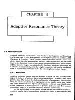
Figures 6.1 and 6.2 show that, although ring spinning has the widest spinnable
</div>
<span class='text_page_counter'>(2)</span><div class='page_container' data-page=2>
© 2003 by CRC Press LLC
<b>TABLE 6.1</b>
<b>Classification of Spinning System</b>
<b>Spinning </b>
<b>methods</b> <b>Common feature</b> <b>Technique</b>
<b>Type of </b>
<b>twisting </b>
<b>action during </b>
<b>spinning</b>
<b>Type of yarn </b>
<b>structure produced</b>
<b>for fiber consolidation</b>
<b>Trade </b>
<b>names</b>
Ring spinning Ring and traveler Single strand twisting
Double-strand ply twisting
Real
Real
Twisted: S or Z
Twisted: S or Z
Various
Sirospun/Duospun
OE spinning Break in the fiber mass flow
to the twist insertion zone
Rotor spinning
Friction spinning
Real
Real
Twisted: Z + wrapped
Twisted: Z + wrapped
Various
Dref II
Self-twist spinning Alternative S and Z folding twist False twisting of two fibrous
strands positioned to self-ply
False S and Z twisted Repco
Wrap spinning Wrap of fibrous core by either
(a) filament yarn
(b) staple fibers
Alternating S and Z twist plus
filament wrapping
Hollow spindle wrapping
Air-jet fasciated wrapping
False
False
False
S and Z + filament
wrapped
Wrap
Wrapped + twisted
Selfil
Parafil
(Dref III, MJS, Plyfil)
Twistless Coherence of the yarn constituents
</div>
<span class='text_page_counter'>(3)</span><div class='page_container' data-page=3>
with automation, does not always offer the best process economics. The key to its
dominance of world markets is the suitability of the ring-spun yarn structure and
properties to a wide range of fabric end uses.
Before explaining the operating principles of the listed spinning systems, it is
useful to consider the technological equations applicable to all of them. All spinning
systems have the three basic actions shown below for producing staple yarns:
Ring Spinning
Rotor Spinning
MJS (Air-Jet)
Dref
Hollow Spindle
Siro-Duo Spinning
Repco
Claimed Economic Count Range (Tex)
300 5
25 10
100
15 7
5K II 100 III 33
2K 16 5
100 (2 × 50’s) 20 (2 × 10’s)
<b>FIGURE 6.1</b> Economic count range of spinning systems.
Ring
Rotor
MJS/Air Jet Spinning
Dref III/Friction Spinning Dref II/Friction Spinning Hollo
w Spindle
Repco
Siro-Duo Spinning
Bob T
ex
Short Staple
Processes 25 mm – 50 mm
Long Staple
Processes 51 mm – 215 mm
Spinning Methods
Production Speed (m/min
-1)
700
600
500
400
300
200
100
0
</div>
<span class='text_page_counter'>(4)</span><div class='page_container' data-page=4>
It was explained in Chapter 1 that to spin a yarn from a given fiber type, certain
specifications are required, such as the yarn count and, in particular, the level of
twist. The concept of twist factor was also explained. These parameters are key
variables in the technological equations that give us the production rate of any
spinning system.
With respect to the yarn count, the required level of attenuation or total draft,
<i>DT</i>, of the system should allow for twist contraction as described in Chapter 1. To
do so in practice, a sample of yarn is spun to the required twist level, the resulting
increase in count is determined, and the total draft is readjusted to give the specified
count. Similar to the drafting considerations in Chapters 1 and 2, the total draft is
calculated as the ratio of the count of the feed material to the spinning machine and
the count of the yarn. This value is then used to set the relative speeds of the drafting
components of the machine.
If <i>NI</i> is the rotation speed of the twisting device used in spinning the yarn, then, as
we saw in Chapter 1, the twist factor, <i>TF</i>, the yarn count, <i>C</i> , the level of twist, <i>Y</i> <i>t</i>,
and <i>NI</i> have the relation
(6.1)
(6.2)
Assuming that a machine has <i>NM</i> number of spinning positions, commonly referred
to as the number of spindles, and an operating efficiency of ε%, then the production
per spindle, <i>PS</i>, in kg/h–1 is
(6.3)
and the production per machine, <i>PM</i>(again, in kg/h–1) is
Attenuation of the feed
material to the required
count
Insertion of twist into the
attenuated fiber mass to
bind the fibers together
Winding of the spun yarn
onto a bobbin to produce a
suitable package
<b>Basic Actions in Spinning Yarns</b>
<i>DT</i>
Sliver tex
Yarn tex
--- Delivery roller surface speed( )<i>Vd</i>
Feed roller surface speed( )<i>Vf</i>
---= =
<i>TF</i> <i>tCy</i>
1 2⁄
=
<i>t</i> <i>NI</i>
<i>Vd</i>
---=
<i>PS</i>
<i>VdCY</i>60
106
---=
<i>PM</i>
<i>VdCY</i>60<i>NM</i>ε
</div>
<span class='text_page_counter'>(5)</span><div class='page_container' data-page=5>
Substituting for <i>V</i> (Equations 6.1 and 6.2),<i>d</i>
(6.4)
The above equations are applicable to any spinning system. However, with some
systems, the rotational speed of the yarn cannot be readily determined. It then may
be estimated from twist (or some similar parameter, e.g., twist angle) and delivery
speed measurements using Equation 6.2.
<b>6.1.1 RINGAND TRAVELER SPINNING SYSTEMS</b>
<i><b>Definition: </b></i>The ring and traveler spinning method is a process that utilizes roller
drafting for fiber mass attenuation and the motion of a guide, called a
<i>traveler,</i> freely circulating around a ring to insert twist and simultaneously
wind the formed yarn onto a bobbin.
The ring and traveler combination is effectively a twisting and winding mechanism.
<b>6.1.1.1 Conventional Ring Spinning</b>
Figure 6.3 illustrates a typical arrangement of the ring spinning system. The drafting
system is a 3-over-3 apron-drafting unit. The fibrous material to be spun is fed to
the drafting system, usually in the form of a roving. Similar to the roving frame,
the back zone draft is small, on the order of 1.25, and the front zone draft is much
higher, around 30 to 40. The aprons are used to control fibers as they pass through
the front zone to the nip of the front rollers. Chapter 5 describes the principles of
roller drafting. It is nevertheless important to note here that apron drafting systems
are suitable for use only where the fiber length distribution of the material to be
processed is not wide (i.e., not a significant amount of very short and very long
fibers). When the standard distribution is higher, the material is more commonly
drafted with a false-twister, which essentially replaces the drafting apron as depicted
in Figure 6.4. This is typical of the ring spinning system for producing woolen yarns
in which the slubbings from the woolen card are fed through the false-twister to the
front rollers of the drafting system.
As Figure 6.3 shows, a yarn guide, called a <i>lappet,</i> is positioned below the
front pair of drafting rollers. The ring, with the spindle located at its center, is
situated below the lappet. Importantly, the lappet, the ring, and the spindle are
coaxial. The traveler resembles a C-shaped metal clip, which is clipped onto the
ring. A tubular-shaped bobbin is made to sheath the spindle so as to rotate with
the spindle. The ring rail is geared to move up and down the length of the spindle;
its purpose is to position the ring so that the yarn is wound onto the bobbin in
successive layers, thereby building a full package, which is fractionally smaller in
diameter than the ring. The yarn path is therefore from the nip of the front rollers
of the drafting system, through the eye of the lappet and the loop of the traveler,
and onto the bobbin.
<i>PM</i>
<i>NICY</i>
3 2⁄
</div>
<span class='text_page_counter'>(6)</span><div class='page_container' data-page=6>
Essentially, the drafting system reduces the roving or slubbing count to an
appropriate value so that, on twisting, the drafted mass of the required yarn count
is obtained. As the front rollers push the drafted material forward, twist torque
propagates up the yarn length (i.e., from <i>c</i> to <i>a</i>) and twists the fibers together to
form a new length of yarn. The tensions and twist torque cause the fibers to come
together to form a triangular shape between the nip line of the front drafting rollers
and the twist insertion point at <i>a</i>. This shape is called the <i>spinning triangle.</i> The
differing tensions between the fibers in the spinning triangle are considered to be
responsible for an intertwining of the fibers during twisting, termed migration. The
degree of migration strongly influences the properties of the spun yarn, and this
feature of the yarn will be discussed in the later section.
+
+
+
+
+
+
Roving
Drafting
System
Lappet Yarn
Guide
Nip Line
Twist Insertion
Point At "a"
Bobbin
(Or Cop)
Vien Package
Balloon
Diameter
Lb
Yarn
Balloon
Length
= bc
Traveller
Ring
Rail
Spindle
Ring
C
D
θ
Ts
Ts
Ts
σ
a
b
</div>
<span class='text_page_counter'>(7)</span><div class='page_container' data-page=7>
<b>6.1.1.2 Spinning Tensions</b>
The bobbin rotates with the spindle and, because the yarn passes through the
traveler and onto the bobbin, the traveler will be pulled around the ring and the
yarn pulled through the traveler and wound onto the bobbin. As the traveler
circulates the ring, it carries with it the yarn length, <i>Lb</i>(= <i>bc</i>),extending from the
lappet to the traveler. While <i>Lb</i>circulates the ring, the circular motion causes it to
arc outward away from the bobbin. Air drag and the inertia of <i>Lb</i> result in the arc
length having a slight spiral as it circulates with the traveler (see Chapter 8). The
rotational speed of the spindle can be up to 25,000 rpm. The three-dimensional
visual impression given by the circular motion of <i>Lb</i> is of an inflated balloon,
termed the <i>spinning balloon</i> or <i>yarn balloon.</i> Hence, <i>Lb</i> is called the <i>balloon length,</i>
<i>H</i> is the balloon height (the vertical distance from the plane of the ring to the
plane of the lappet), and <i>D</i> is the balloon diameter. The forces generated by the
motion of the traveler and the pulling of the yarn through the traveler result in
yarn tensions that govern the actual shape of the spinning balloon. Chapter 8
discusses in more detail yarn tensions and spinning balloons in relation to the
physical parameters of spinning.
Cheese Of Slubbing
Slubbing
Back Rollers
False Twister
Device
Front Rollers
Cop of Yarn
Back Rolls
Slubbing
False Twist
Front Rolls
Real Twist
Twist Runs to Nip of
Back Rollers and
Controls Fiber Flow
</div>
<span class='text_page_counter'>(8)</span><div class='page_container' data-page=8>
The tensions generated in the yarn are indicated in Figure 6.3 and are related
according to the following equations:
<i>TO</i> = <i>TSeK</i>θ (6.5)
<i>TW</i> = <i>TReP</i>α (6.6)
where <i>TS</i> = the spinning tension
<i>TO</i>, <i>TR</i> = the tensions in the balloon length at the lappet guide and at the
ring and traveler, respectively
<i>TW</i> = the winding tension
<i>K</i> = the yarn-lappet coefficient of friction
θ and α = the angles shown in the figure
<i>P</i> = yarn-traveler coefficient of friction
<i>TO</i>and <i>TR</i>are related by (see Chapter 8)
<i>TO</i> = <i>TR</i> + <i>mR</i>2ω2 (6.7)
where <i>m</i> = mass per unit length
These tensions are important to twist insertion and the winding of the yarn onto the
bobbin, and also to end breaks during spinning.
Consider first the winding action. As the traveler is pulled around the ring, the
centrifugal force, <i>C</i>, on the traveler will lead to a friction drag, <i>F</i>, where
<i>F</i> = µ<i>C</i> (6.8)
<i> </i>
<i>C</i> = <i>MRR</i>ω2 (6.9)
where <i>M</i> = traveler mass
<i>RR</i> = ring radius
ω = angular velocity of the traveler (= 2π<i>Nt</i>)
The yarn must be wound onto the bobbin at the same linear speed, <i>VF</i>, as the
front drafting rollers are delivering fibers to be twisted. This means that <i>F</i> must be
sufficient to make the traveler’s rotational speed lag that of the spindle. Hence, if
<i>DB</i> is the bobbin diameter, then
(6.10)
where <i>Ns</i> = spindle speed (rpm)
<i>Nt</i> = traveler speed (rpm)
The wind-up speed is therefore the difference between the spindle and traveler speed.
It is evident that, as the bobbin diameter increases with the buildup of the yarn, the
traveler speed increases. The traveler speed will also change with the movement of
<i>Ns</i>–<i>Nt</i>
<i>VF</i>
π<i>DB</i>
</div>
<span class='text_page_counter'>(9)</span><div class='page_container' data-page=9>
the ring rail to form successive yarn layers on the bobbin. The common way of
layering the yarn on the bobbin is known as a <i>cop build</i> in which each layer is
wound in a conical form onto the package. The top of the cone is called the <i>nose</i>
and the bottom the <i>shoulder</i>. In practice, it is found that the conical shape gives easy
unwinding of the yarn without interference between layers, as the yarn length is
pulled from the nose over the end of the bobbin. To make a cop build, the ring rail
cycles up and down over a short length of the bobbin, with a slow upward and a
fast downward motion. This increases the size of the shoulder more quickly than
the nose. This cycling action of the ring rail progresses up the bobbin length in steps,
each step taken when the shoulder size reaches almost the ring diameter.
<b>6.1.1.3 Twist Insertion and Bobbin Winding</b>
Let us consider now the action of twist insertion. From the definition, it is clear that
one revolution of the traveler around the ringinserts one turn of twist into the forming
yarn. However, for a fuller understanding of the twist insertion, we need to consider
where the twist originates, the twist propagation, and twist variation caused by the
cop build action.
Imagine two yarns of contrasting colors passed through the nip of the front
drafting rollers and threaded along the yarn path to the bobbin. With the front drafting
rollers and the ring rail stationary, and only the spindle driven, using high-speed
photography, we would see that, within the first few rotations of the traveler, the
twisting of the two yarns together originates in the balloon length between the lappet
guide and the traveler.4<sub> The action of twisting the two yarns together is called </sub><i><sub>plying</sub></i>
or <i>doubling</i>, so no ply twist would be seen in the length between the traveler and
the spindle or between the lappet guide and the front drafting rollers. It should be
clear from Equation 6.10 that no yarn would be wound onto the bobbin and that the
rotational speed of the traveler would be equal to the spindle speed.
If the above experiment is repeated, but this time with the front drafting rollers
and the ring rail operating, then the following would be observed. The initial length
wound onto the bobbin will be of the two yarns in parallel and not twisted together.
As above, the ply twist originates in the balloon length and, as it builds up in the
balloon length, it propagates toward the delivery rollers. The frictional resistance at
the lappet opposes the twist torque propagation, reducing the amount of twist passing
the guide. The forces acting at the point of contact of the yarn and traveler prevent
the twist torque propagating past the traveler toward the bobbin. However, as sections
of the yarn leave the region of the balloon length and are pulled through the traveler
and wound onto the bobbin, they retain the nominal twist given by Equation 6.2.
Hence, under steady running conditions, the twist level in the balloon length will
be greater than in the length above the lappet and slightly larger than in the length
wound onto the bobbin.
</div>
<span class='text_page_counter'>(10)</span><div class='page_container' data-page=10>
Hence,
<i>Ns</i> – <i>Nt</i> = [<i>VF</i> – <i>VR</i>]/π<i>DB</i> (6.11)
when the ring rail moves up toward the nose of the cop, and
<i>Ns</i> – <i>Nt</i> = [<i>VF</i>+ <i>VR</i>]/π<i>DB</i> (6.12)
when moving downward toward the shoulder. It is evident then that <i>Nt</i>will vary
cyclically with the movement of the ring rail. The increase in the bobbin diameter
as the yarn is wound onto the bobbin will increase <i>N</i> , and this will be superimposed <i>t</i>
on the ring rail effect. Clearly, then, there will be some variation in the twist per
unit length along the yarn length wound onto a bobbin. In practice, the variation is
small and often falls within the random variation of measurements. Furthermore,
the difference between <i>Ns</i> and <i>Nt</i> is also small, and therefore, for practical purposes,
<i>Ns</i> is used in calculating the nominal or machine twist.
From the above discussion, it should be evident to the reader that the size of the
ring diameter limits the diameter of the yarn package that can be built in ring
spinning. Package size is an important factor in machine efficiency, since each time
a package is changed, the spinning process is disrupted, adding to the stoppage or
downtime of the spindles. In modern high-speed weaving (i.e., shuttle-less looms)
and knitting processes, yarn package sizes of approximately 2.5 to 3 kg are required;
therefore, the yarn packages from ring and traveler processes have to be rewound
to make larger packages. Chapter 7 describes the principles involved in the rewinding
of spun yarns. However, here, it is important to point out that, when many ring-spun
yarn packages are involved in making a full rewound package for subsequent
pro-cesses, the quality of the fabric can be affected. This is because yarns from different
spindles on a machine may vary in properties, owing to small differences in the
machine elements from one spinning position to another. More detrimentally, there
unknowingly may be a few incorrectly functioning spinning positions, i.e., <i>rogue </i>
<i>spindles.</i> When the yarns from the different spindles are pieced together, they provide
a continuous length on a large rewound package, and the variations in this continual
length will eventually be incorporated into the fabric. If yarn from the rogue spindle
is part of the pieced length, it may lead to a degrading fault in fabric. The larger the
ring-yarn packages, the fewer for rewinding onto larger packages. There is also an
advantage for the rewinding process, as there would be few piecings and less
stoppage time to replace empty ring bobbins with full ones.
</div>
<span class='text_page_counter'>(11)</span><div class='page_container' data-page=11>
ring.5<sub> With the small contact area between the C-shaped traveler and ring, the heat </sub>
can build up locally to much higher temperatures. Increased spindle speed and/or
ring diameter, and thereby traveler speed, may then lead to a situation in which
localized melting of the traveler occurs, and the traveler can no longer be effectively
used for spinning. This is usually referred to as <i>traveler burn,</i> because, visually, the
place on the traveler that makes contact with the ring becomes the blue-black color
of heated metal.
In addition to the factor of traveler burn, there is the aspect of wear on both
traveler and ring. The faster the traveler speed, the shorter the traveler life. The
cautious spinner tends to quote a maximum practical speed for steel travelers to be
within 35 to 40 m/s. However, research and development work by ring and traveler
manufacturers, aimed at either reducing frictional wear and improving conduction
of the heat generated at the ring-traveler interface, has resulted in new designs of
the ring and traveler combination,6<sub> the use of carbon rich steels, lubricated rings (oil </sub>
impregnated sintered),7 <sub>and, in some cases, ceramic rings</sub>8<sub> and special finishes. </sub>
Certain developments have involved slowly rotating the ring while retaining the
relative speed of the traveler. This process is called <i>the living ring</i>.9
Claims have been made for maximum traveler speed of 50 to 60 m/s.10,11
Figure 6.5 shows an example of an improved design, compared with the
conven-tional ring-traveler geometry, and it can seen the greater surface contact would be
beneficial.
We can reason from the above that increasing the yarn package size by using
large diameter rings may mean reducing spindle speed and thereby production speed.
Another means of increasing package size is by using a longer package length over
which the yarn is wound. This is called the <i>lift</i>, and it inevitably means that the
spinning position has a longer balloon height and balloon length. Two main factors,
however, control the maximum balloon height: (1) balloon collapse caused by the
F.R
F.R
H
LF
LS
FTK
</div>
<span class='text_page_counter'>(12)</span><div class='page_container' data-page=12>
formation of a node in the yarn balloon during spinning and (2) increased yarn
tension and thereby increased interruptions of the spinning by yarn breaks (i.e., end
breaks) resulting in a lower machine efficiency, ε%.
From the simple theory of a vibrating string, it can be shown that the balloon
height, <i>H,</i> balloon tension, <i>TB</i>, the spindle speed, <i>NS</i>, and the yarn count, <i>C</i> , are <i>Y</i>
related by
(6.13)
where <i>C</i> = the constant of proportionality
For a given yarn count and spindle speed, there must be a minimum balloon
tension below which the balloon length, <i>Lb</i>, has the tendency to form a nodal point
between the lappet and the traveler, resulting in balloon collapses. If we therefore
wish to increase the balloon height for a given count and spindle speed, the balloon
tension must be increased. However, as was stated earlier, too high a tension could
result in increased end breaks and low machine efficiency. Since the traveler is pulled
around the ring circumference by the yarn, the drag of the traveler mass, <i>M</i>,
influ-ences the tension in the yarn. Also, if <i>H</i> is large, the required <i>M</i> could result in a
spinning tension greater than the strength of the yarn being spun. To circumvent the
use of too heavy a traveler, balloon control rings (see Figure 6.3) are used to prevent
a nodal point from forming in the balloon profile (see Chapter 8). The lightest traveler
mass, <i>M</i>, for a given balloon height, yarn count, and ring diameter <i>DR</i> is given by
(6.14)
where <i>K</i> = the constant of proportionality
With medium to coarse count yarns, say 40 to 100 tex, building sizeable packages
requires the use of a balloon control ring. For very coarse counts, such as in the
area of carpet yarns, it becomes necessary to spin with a collapsed balloon in order
to produce a useful size spinning package for rewinding. See Figure 6.6. As the
figure shows, the yarn balloon length partially wraps around the spindle, but such
coarse yarns have sufficient strength to overcome the frictional drag of the spindle
without breaking. The frictional contact with the spindle will resist the twist
prop-agation toward the front drafting rollers, this is additional to the effect of the lappet.
A false-twisting device fitted on the end of the spindle is therefore used to prevent
spinning beaks because of low twist reaching the spinning triangle.
<i>6.1.1.3.1 Spinning End Breaks</i>
The weakest part of a forming yarn will be at the point of twist insertion. In ring
spinning, this is the spinning triangle, just below the front drafting rollers (see Figure
6.3). During ring spinning, most end breakages will occur here. Three factors are
<i>H</i> <i>C</i> <i>TB</i>
<i>CYNS</i>
2
( )
---
12
---=
<i>M</i> <i>K H</i>
2
<i>CY</i>
<i>DR</i>
</div>
<span class='text_page_counter'>(13)</span><div class='page_container' data-page=13>
therefore of importance: (1) the number of fibers in the triangle and the variation of
this number, (2) the propagation of twist to the apex of the triangle, and (3) the
mean tension and tension fluctuation.
Clearly, the greater the number of fibers in the cross section of the forming yarn,
the stronger the yarn will be to withstand the spinning tension and tension
fluctua-tions, provided that the mean spinning tension is kept well below the breaking load
of the yarn (typically 30% below mean yarn strength). End breakage problems will
arise when the number of fibers in the cross section of the fiber ribbon varies
significantly and/or the peak value of tension fluctuation is too high.
The variation of the number of fibers in the cross section causes thin and thick
places in the fiber ribbon. As these pass through the twist insertion point at the apex
of the spinning triangle, the thin places are more easily twisted than thick places;
thin parts of the ribbon will tend to have more twist than thicker parts. A very thin
part of the ribbon will become over twisted and weak (see ), and this
will make the yarn susceptible to peak tension fluctuations.
From Equation 6.5, it is evident that the friction µ and the angle θ are important
factors to the mean spinning tension, <i>TS</i>, and the fluctuation of this tension. It can
</div>
<span class='text_page_counter'>(14)</span><div class='page_container' data-page=14>
be seen from Figure 6.3 that θ will vary as the balloon length, <i>H</i>, rotates with the
traveler. The spinning geometry therefore must ensure that fluctuation in <i>TS</i> is kept
small.
<i>TS </i>is also dependent on the winding tension. Consequently, it is directly
propor-tional to the mass of the traveler and inversely proporpropor-tional to the bobbin radius;
the spinning tension is usually high at the start winding and decreases as the package
builds up. The appropriate traveler mass must be used in accordance with the yarn
count (i.e., number of fiber in the yarn cross section), and the bobbin radius must
not be smaller than 40% the ring radius (see Chapter 8).
<b>6.1.1.4 Compact Spinning and Solo Spinning</b>
These two systems are essentially modifications to the conventional ring spinning
process with the aim of altering the geometry of the spinning triangle (see Figure
6.7) so as to improve the structure of the ring-spun yarn by more effective
binding-in of surface fibers binding-into the body of the yarn. This reduces yarn hairbinding-iness, and binding-in
the case of Solo spinning, makes single worsted/semi-worsted yarns suitable for use
as warps in weaving and therefore dispensing with ply twisting.
As the name implies, with compact spinning (also called <i>condensed spinning</i>),
the fibers leaving the front drafting roller nip are tightly compacted, making any
Conventional Compact Solo
To Ring and
Traveler
Nip Line
Wy
Ts
Ts Ts Ts
W2
W1
Edge
fibers
</div>
<span class='text_page_counter'>(15)</span><div class='page_container' data-page=15>
sign of a spinning triangle at the twist insertion point virtually imperceptible. The
importance of compaction can be explained with reference to Figure 6.7. In the
conventional system, the fibers are fed at width <i>W</i><sub>1</sub> into the zone of twist insertion.
This width is the result of the attenuation by roller drafting and is dependent on
such factors as the count of the in put material to the drafting system, i.e., of sliver
or roving, the twist level in the roving feed, and the level of draft. The first two
factors govern the width of the material fed into the drafting system, and <i>W</i><sub>1</sub> is
directly proportional to this width. The level of drafting has a strong effect in that
the higher the draft, the wider <i>W</i><sub>1</sub>.13<sub> The acuity of angle of the spinning triangle </sub>
in the twist insertion zone is directly proportional to <i>W</i><sub>1</sub>, twist level, and the
spinning tension <i>TS</i>,but it is inversely proportional the yarn count. That is to say,
these factors govern the difference between <i>W</i><sub>1</sub> and the yarn diameter, <i>WY</i>, at the
apex of the spinning triangle. Because of this difference, the leading ends of fibers
at the edges of the ribbon are not adequately controlled and twisted into the yarn
structure. The result is that these fibers either have a substantial part of their length
projecting from yarn surface as hairs, and thereby contributing little to the yarn
strength, or they escape twisting all together as fly waste. In Chapter 1, we saw
that yarn hairiness can be a problem in downstream processes and to fabric
appearance.
Reducing <i>W</i>1 to <i>W</i>2 greatly improves the control and twisting into the yarn
structure of the edge fibers. It should also be noted that, with the problem of
incorporating edge fibers into the forming yarn and the resistance to twist
propa-gation from the yarn balloon zone, the strength at the apex of the spinning triangle
is generally only one-third of the yarn strength. This makes the spinning triangle
a potential weak spot at which breaks occur during spinning. The reason is that
the tension induced into fibers by the spinning tension is very small at the center
of the spinning triangle as compared with at the edges. Therefore, when spinning
fine yarns or yarns with low twist levels, the loss or the poor incorporation into
the yarn of edge fibers means insufficient strength to withstand the spinning
tension, and breaks occur. By greatly narrowing the width of the spinning triangle,
compact spinning should improve both spinning efficiency and the structure and
properties of ring-spun yarn. The structure-property relation of yarns is discussed
in Section 6.2.
In Solo spinning, the drafted ribbon, instead of being compacted, is divided into
sub-ribbons or strands that form the spinning triangle. At the apex of the triangle,
the strands are twisted together, similar to plying of several yarns. This confers better
integration of the edge fibers as fibers are trapped within and between strands.
Table 6.2 lists the basic features of the four techniques currently used to compact
the spinning triangle. All utilize air suction and are essentially either a modification
or an attachment to the front of a conventional type drafting system.
With the ComforSpin process (Figure 6.8), a perforated drum (A) replaces the
</div>
<span class='text_page_counter'>(16)</span><div class='page_container' data-page=16>
<i>W</i>1 (see Figure 6.7). Suction is applied from within the drum through a slotted tubular
screen (S) so that, as the perforated drum rotates, the screen enables a controlled
airflow through the perforations passing over the slot to firmly hold the drafted fiber
ribbon to the drum surface, leaving the nip line at roller B. The slot is specially
shaped for the drafted ribbon to become compacted from width <i>W</i><sub>1</sub> to <i>W</i><sub>2</sub> by the
<b>TABLE 6.2</b>
<b>The Compacting Systems in Ring Spinning</b>
<b>Manufacturer</b> <b>Trade names</b> <b>Basic features</b>
Rieter Machine
Works Ltd.
Com4Spin or
ComforSpin
4-over-3 double apron drafting system with perforated
bottom front roller and two top rollers; drafted ribbon
compacted by air suction through bottom front roller
Spindelfabrik
Suessen
EliTe 3-over-3 double drafting system with addition roller and
special lattice apron, {moving around slotted, air suction
tube (<i>tubular profile</i>) for compaction of drafted ribbon
Zinser
Textilmaschinen
GmbH
Air-Com-Tex
700
4-over-4 double apron drafting system with perforated
apron circulating around top front roller; drafted ribbon
in front zone compacted by suction through perforated
apron
Maschinen-und
Anlagenbau
Leisnig GmbH
P4 4-over-4 double apron drafting system with perforated
apron circulating around bottom front rollers; drafted
ribbon in front zone compacted by suction through
perforated apron
W1
W2
C A
B
DA
</div>
<span class='text_page_counter'>(17)</span><div class='page_container' data-page=17>
time it reaches the final nip line at roller C. Beyond this, twist is inserted as in
conventional ring spinning.
In the Elite system, the basic drafting rollers are retained with an additional
unit fitted at the front (see Figure 6.9). The added unit consists of a transport apron
of lattice weave — 3,00 pores/cm2<sub>, which passes closely over the surface of a </sub>
specially shaped, slotted, suction tube — <i>tubular profile.</i> Suction occurs at the
interstices of the apron moving across the slot of the tubular profile. The plan view
shows that the slot can be inclined at 30° to the center line of the apron, which
thereby causes the motion of the apron to effect a rolling of the drafted ribbon as
the ribbon is being compacted. This is useful when spinning uncombed cotton, i.e.,
<i>carded cotton,</i> as the very short fibers become more embedded in the final yarn.
The additional top roller is geared to the top front drafting roller at a slightly higher
surface speed. The additional top roller drives the transport apron via friction contact
at the nip line. The drafted ribbon is therefore under tension, straightening fibers,
during compaction.
The Air-Com-Tex 700 and CSM units use an alternative apron arrangement to
the Elite unit for compaction, but, similar to the latter, compacting occurs after the
front drafting rollers. The alternative arrangement is simply an added conventional
</div>
<span class='text_page_counter'>(18)</span><div class='page_container' data-page=18>
apron-drafting zone with a line of perforations down the middle of the apron width
through which suction is applied. The Air-Com-Tex 700 has only a perforated bottom
apron, whereas the CSM has double aprons, of which only the top one is perforated.
Figure 6.10 shows the attachment at the front pair of drafting rollers used for
the Solo spinning process. This consists of an addition roller (F), the Solospun roller,
mounted via a bracket clip (C) onto the top front-drafting roller shaft (E) of the
drafting arm. The Solospun roller has a series of circumferential grooves along its
length, and it forms a nip line with the bottom front-drafting roller. It is the presence
of the grooves in the Solospun roller that results in the drafted ribbon being divided
into a number of strands that are twisted together to form the Solospun yarn.
<b>6.1.1.5 Spun-Plied Spinning</b>
A singles conventional ring-spun yarn of low twist will be hairy and have low
abrasion resistance but, if woven or knitted, would give the fabric a soft feel. The
above Solo and compact ring spinning systems produce singles yarns with much
lower hairiness than conventional ring-spun yarns; however, these systems have yet
to become widely used. To weave or knit low twisted conventional ring-spun yarns,
it becomes necessary to trap the surface fibers by producing a twofold yarn. The
conventional way of producing a twofold yarn is to ply together two single yarns
using one of various techniques to be described later. There are economic advantages
to be obtained if spinning and plying can be achieved as one process, and Figure
6.11 shows how this may be done.
Figure 6.11 shows two strands of roving passing through the same drafting unit
but separated so that they emerge from the front drafting rollers a fixed distance
apart. They then converge to a point at which the twist torque propagating from the
A
F
</div>
<span class='text_page_counter'>(19)</span><div class='page_container' data-page=19>
yarn ballooning region inserts twist into the separate strands and plies the twisted
strands together to form the twofold yarn. The strand twists propagate to form two
very small, almost imperceptible, spinning triangles at the front drafting rollers. The
strand and ply twists are of the same twist direction (see Figure 6.12). In case one
of the strands breaks during spinning, the yarn guide below the front rollers has the
function of breaking the remaining strand, and the suction tube (termed a <i>pneumafil</i>)
is positioned near the front roller to collect the fibers that would still be issuing from
the front rollers. Figure 6.13 shows a variation of the spun-plied arrangement, called
<i>Duospun</i>,14<sub> where a specially designed suction nozzle replaces the yarn guide and </sub>
pneumafil.
It is important to note that twist must be present in the individual strands if the
surface fibers are to be suitably held in the twofold yarn structure. With only ply
twist to hold fibers into the yarn structure, there will still be many fibers having
much of their length projecting from the plied structure. With strand and ply twist,
the fibers are more effectively trapped by every turn of ply twist, and for twist to
be inserted into the strands, they must be spaced apart.
As fibers leave the front drafting rollers, they are incorporated into the strands
in a similar way to conventional ring spinning. Therefore, unless the strand twist is
high, there will be some fiber lengths projecting from the strands. The propagation
of strand twist toward the nip of the front rollers means that a given projecting length
will be rotating about the axis of the strand into which the remaining length of the
fiber is twisted. Owing to the geometrical arrangement of the strands, as they
converge, many of the projecting lengths will eventually strike the neighboring stand,
</div>
<span class='text_page_counter'>(20)</span><div class='page_container' data-page=20>
which prevents them from rotating further. As the strands become plied, these fiber
lengths are trapped between the two strands. This mechanism of trapping is called
<i>yarn-formation trapping.</i> However, most surface fibers will have their lengths twisted
into a strand prior to being trapped by the ply twist. This mode of trapping is called
<i>strand-twist migration trapping.</i>
There is a balance of tensions at the convergence point, where the strand twist
angle will almost coincide with the ply twist angle. Better trapping of the fibers
occurs with greater differences between the twist angles. By varying the spinning
tension, the twist propagating into the strands will vary, and so will the twist angle.
Variations in spinning tension occur with the cyclic up-and-down motion of the
ring rail. When the convergence point is in its top position, the twist in the strand
is at a maximum. As the tension in the plied yarn increases with the downward
movement of the ring rail, the frictional contact between the strands at the
conver-gence point increases, decreasing the amount of twist propagating into each strand
and the strand twist angle. There is a resulting decrease in twist contraction of the
strands, and the convergence point moves downward with the associated increase
in strand lengths.
With the upward movement of the ring rail, the tension in the plied yarn
decreases, enabling the strand twist and twist angle to increase; the strand lengths
shorten with twist contraction, and the convergence point moves upward. The cyclic
motion of the ring rail causes the convergence point to also cycle up and down and
effects better trapping of fibers in the spun-plied structure.
</div>
<!--links-->