148819A BID item proj treat SOW 4 30 12
Bạn đang xem bản rút gọn của tài liệu. Xem và tải ngay bản đầy đủ của tài liệu tại đây (2.68 MB, 10 trang )
BID ITEMS DESCRIPTION OF WORK (print this document as 11x17)
SCOPE OF WORK
This scope of work requires the replacement of the existing CCA treated wooden handrail, mid-rail, and posts and CCA treated laminated decking for the Bayou Coquille Bridge, Pipeline Canal Bridge, and Pipeline Canal
Observation Deck including the stair decking and associated features that shall result in a new sustainable system. Some treated structural members shall be replaced as noted and additional structural members install to
accommodate the new decking system. All quantities and sizes provided shall be verified by the Contractor to ensure a complete system that meet the intent of the existing bridges and observation deck. The recommend
decking replacements shall be manufactured by McNichols with options as described further in this document.
The contractor shall not conduct any mechanical vegetation clearing in the project areas or to access the project areas to include; manual or automatic distributors, biological, chemical, equipment, etc. to control floating and
land vegetation. The contractor and NPS Contracting Officer Representative (COR) will work with the Resource Management Division of the park on any and all vegetation hindering completion of the project work. This shall
also include placing new or removed materials on site in a way that they destroy/kill the vegetation.
The NPS is managing invasive plants that forms the mats of vegetation on the water providing access to and located throughout the project site areas. The accessible waterways are shallow with some utility crossings that may
limit access to the project site via boat. The contractor shall submit the type of equipment proposed to access and delivered material to the project site areas for approval by the park. The equipment approved shall be the
only equipment allowed for the duration of the project or until an alternative equipment is submitted to be approved. No equipment will be approved that will mechanically clear vegetation and impact management of the
invasive plants.
Sequence of Construction:
It is suggested that the Contractor start work at the Pipeline Canal Bridge and Observation Deck to allow trail to remain open up
to Bayou Coquille Bridge and observation deck(s) as determined by the park. Provide trail close signage and barriers to prevent
visitors from entering the work area.
EXISTING TREATMENT INFO:
Notes (SHEET 12 AS-Built Drawings 467/41010B-July 6, 1984):
1.
2.
3.
4.
5.
6.
FABRICATED FROM WORM CCA TREATED LUMBER WITH 0.4# RET.
ROUGH SAWN FINISH
ARCHITECTURAL FINISH S&S
A.I.T.C STAMPED AND CERTIFIED
WATERPROOF ADHESIVE
NO FABRICATED STEEL OR HARDWARE FURNISHED BY FABRICATOR
SOUTHERN LAMINATORS, INC., DEHAM SPRINGS, LA
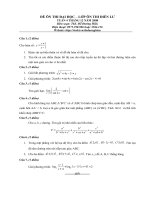
BID ITEM #1
STAIR DECKING:
Treads were not fastened from the top as to protect the stair stringers and this method shall remain for all new work. Where repairs took place creating an hole in the stringer, the Contractor shall first identify all these holes
to the COTR and then fill holes with a fiberglass rod and coat and fill as noted below in this document. Existing stair treads are connected to the stringers via aluminum angle brackets and Hot-Dipped galvanized bolts. Replace
all angle brackets and bolts with new Type 317L stainless steel. See Coating Top of Beams/Stringers Section.
JELA – 4/23/12
148819A - REPLACE BAYOU COQUILLE AND PIPELINE CANAL BRIDGES’ DECKING AND HANDRAILS SOW
BID ITEM DESCRIPTION OF WORK-1
BID ITEM #1 CONT.
Pipeline Canal Bridge – Stair and Landing Decking
Two (2) Type I Stair Sections with Type IIA and IIB deck units/treads having 12 Risers with 11 Treads each – 16 ½” width by 5’-6”length by 3” thick units (24 total units – 16 Type IIA and 8 Type IIB). See Drawing Schedule
Two (2) Type II Stair Sections with Type IIA and IIB deck units/treads having 17 Risers with 16 Treads each – 16 ½” width by 5’-6”length by 3” thick units (32 total units – 22 Type IIA and 10 Type IIB). See Drawing Schedule
Landings (14 total units - 6 Type IIA and 8 Type IIB).
Bayou Coquille Bridge – Stair Decking
See Drawing Schedule (quantity in () show more on drawing). Type IIA and IIB deck units/treads having 11(11) Risers with 11(12) Treads each – 16 ½” width by 5’-6”length by 3” thick units. 11(12) total units – 6 (7) Type IIA and
4 (5)Type IIB and 1 starter unit approximately 12”. Leave one (1) Type IIA unit on end, towards Pipeline Canal, since it is level with the trail system, and add new fiberglass decking on top.
TYPICAL:
Type IIA deck units On one side, has a ½” diameter hole 2” inches on center (o.c.) from the length overhang edge and 8 ¼” o.c. via the width side for the angle bracket bolt. Deck Unit overhang is 4” each side.
Type IIB deck units at posts are with notches. On one side, the deck has a ½” diameter hole 2” inches o.c. from the length overhang edge and 8 ¼” o.c. via the width side for the angle bracket bolt. The notches are 4” from the
length overhang side and 6” from the width side with 2 ¼” from the 1/2” diameter hole. See Drawing Schedule Sheet 5/15.
The Contractor shall remove all glulam treated decking and/or structural members as required from the stir and bridge structures. Inspect substructure to be repaired or replaced in-kind. The COTR may request to have the
best material set aside for Park to keep. Otherwise, all removed decking is the responsibility of the Contractor and must be disposed of properly outside of the park.
RECOMMENDED REPLACEMENT DECKING:
-The Contractor shall replace all stair treads with gray McNichols Pultruded MS-T-1215 ( 1 ½” thickness) Grating with a slip resistant gritted surface decking system with options. Options to add:
Toe plate – Provide McNichols Fiberglass SPF, .125 gauge, Side Kickplate, 4” tall cut to length 5’-6” (66”) for use as stair risers. Alternative riser material to use: McNichols Perforated Round Hole (1/4”) Metal, 316L stainless
steel, 16 guage, and mill finish cut to 5” high for use as stair risers. Field Verify measurements and submit material to be installed including how toe plate and decking will be connected.
Notching – Provide notches in new material per the type of panel, size, quantities, and location as described above.
Cut to Size – Provide fiberglass decking cut to sizes as stated above.
Drawing Required - Submit shop drawings representing each type and deck panel size including notches, toe plate, and anchoring system to be used for existing drilled holes and new brackets.
Sealing – New decking shall be sealed by manufacture per their recommendation in a humid outdoor environment. Verify with the COTR and manufacture before adding this option to the order.
Hardware – Shall be produced by decking manufacturer’s 316 stainless steel clips, anchors, hardware, etc. Any hardware not available by the manufacture as stainless steel shall be fabricated in stainless steel to match
manufacture’s required/designed hardware. Use McNichols 316 Stainless Steel Type F2 1.5” Fastener (section joining), Type M2 1.5H 1.5sq/RT or Type M2 1.5sq Fastener without hardware (substructure anchoring) – See
sketch drawing, or Type J2 1.5” Fasteners (substructure anchoring). Anchor Type M2 and Type J2 to new stainless steel angles at existing mounting locations plus new additional angles as required meeting the minimum
manufacturer’s recommendation for anchoring the decking system. Note: The Contractor shall install manufacturer’s hardware not less than the existing anchoring system in-situ, but only increase as needed.
-The Contractor shall replace all existing aluminum angle brackets and bolts with new Type 316L stainless steel angle brackets and bolts, washers, and nuts. No dissimilar metals shall be used on this project. Provide shop
drawings for all replacement hardware and new hardware that shall be fabricated with stainless steel material. See Drawing Schedule sheet 11/15.
BRIDGES AND OBSERVATION PLATFORM DECKING:
Pipeline Canal Bridge 35’-10” long with existing substructure at 3” width x 22 ½” depth glulam joists 4’-4” apart from inside face (4’-10” outside to outside dimension), Typical. Deck Unit overhang is 4” each side. Angle
brackets are installed 3’-0” on center (o.c.) to the substructure.
Type I Deck Units (12 total for removable section with ½ gap) – 5’-6” length by 2’-11 ½” (35 1/2”) width by 3” thick (12 total units as 8 total with notch on one side and 4 total with notch on both sides to receive the lifting
eyebolt).
Pipeline Canal Observation Platform 24’-0” by 15’-16 ½” Angle brackets are installed 34” o.c. to the substructure and staggered at alternating joists.
JELA – 4/23/12
148819A - REPLACE BAYOU COQUILLE AND PIPELINE CANAL BRIDGES’ DECKING AND HANDRAILS SOW
BID ITEM DESCRIPTION OF WORK-2
BID ITEM #1 CONT.
Type III 8’-0” Deck Units (28 total) 8’-0” length by 16 1/2” width by 3” thick (verify).
Type IIIA 4’-0” Deck Units (10 total) 4’-0” length by 16 1/2” width by 3” thick (verify).
Deck Units alternate to stagger the joints. See Drawing Schedule Sheet 6/15.
On one side of each deck unit there is a ½” diameter hole 2” inches o.c. from the length overhang edge and 8 ¼” o.c. via the
width side for the angle bracket bolt.
Bayou Coquille Bridge 80’-0” long with substructure at 3” width x 22 ½” depth glulam joists 4’-4” apart from inside face (4’-10”
outside to outside dimension), Typical. Deck Unit overhang is 4” each side. Angle brackets are installed 3’-0” o.c. to the
substructure.
There are Five (5) sections with Type I Deck Units (6 total for removable/standard sections with ½ gap) – 5’-6” length by 2’-11 ½”
(35 1/2”) width by 3” thick (30 total units as 26 total with notch on one side and 4 total with notch on both sides to receive the
lifting eyebolt).
Power Line Bridge – Not In Contract (N.I.C)
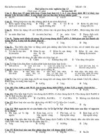
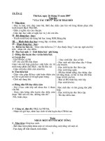
TYPE I LAMINATED DECKING, TYP. (DRWG 467/41,010 pg. 11)
TYPICAL:
The ½ gap was not visible at inspection.
On one side, the deck unit has a ½” diameter hole 2” inches o.c. from the length overhang edge and 17 ¾” o.c. via the width side for the angle bracket bolt. Type I deck units at posts are with notches. The notches are 4” from
the length overhang edge and 3” from the width side. Note the deck is mirrored to fit around the 6”x4” posts.
The Contractor shall remove all glulam treated decking and/or structural members as required from the stir and bridge structures. Inspect substructure to be repaired or replaced in-kind. The COTR may request to have the
best material set aside for Park to keep. Otherwise, all removed decking is the responsibility of the Contractor and must be disposed of properly outside of the park.
RECOMMENDED REPLACEMENT:
-The Contractor shall replace all stair treads with gray McNichols Pultruded MS-T-1215 ( 1 ½” thickness) Grating with a slip resistant gritted surface decking system with options. Options to add:
Notching – Provide notches in new material per the type of panel, size, quantities, and location as described above.
Cut to Size – Provide fiberglass decking cut to sizes as stated above.
Drawing Required - Submit shop drawings representing each type and deck panel size including notches, toe plate, and anchoring system to be used for existing drilled holes and new brackets.
Sealing – New decking shall be sealed by manufacture per their recommendation in a humid outdoor environment. Verify with the COTR and manufacture before adding this option to the order.
Hardware – Shall be produced by decking manufacturer’s 316 stainless steel clips, anchors, hardware, etc. Any hardware not available by the manufacture as stainless steel shall be fabricated in stainless steel to match
manufacture’s required/designed hardware. Use McNichols 316 Stainless Steel Type F2 1.5” Fastener (section joining), Type M2 1.5H 1.5sq/RT or Type M2 1.5sq Fastener without hardware (substructure anchoring) – See
sketch drawing, or Type J2 1.5” Fasteners (substructure anchoring). Anchor Type M2 and Type J2 to new stainless steel angles at existing mounting locations plus new additional angles as required meeting the minimum
manufacturer’s recommendation for anchoring the decking system. Note: The Contractor shall install manufacturer’s hardware not less than the existing anchoring system in-situ, but only increase as needed.
-The Contractor shall replace all aluminum brackets and bolts with new Type 317L stainless steel angle brackets and bolts, washers, and nuts. No dissimilar metals shall be used on this project. Provide shop drawings for all
replacement hardware that shall be made with stainless steel. See Drawing Schedule sheet 11/15.
-The bearing bars for these grating panels are shaped in a T-bar or Rectangular-bar configuration. Pultruded fiberglass grating panels come in a variety of resins and colors (gray for this project) and are available with (for this
project) or without a slip resistant gritted surface.
JELA – 4/23/12
148819A - REPLACE BAYOU COQUILLE AND PIPELINE CANAL BRIDGES’ DECKING AND HANDRAILS SOW
BID ITEM DESCRIPTION OF WORK-3
BID ITEM #2
HANDRAIL, TOP RAIL, MID RAIL, AND POSTS:
Bayou Coquille Bridge
Posts – field verify
Coquille Bridge lift/removable section (6 posts)
-4”x6”x4’-6” Tall at 6’-0” on center (o.c).
Coquille Bridge four (4) standard sections (6 x4 = 24 posts)
-4”x6”x4’-6” Tall at 6’-0” on center (o.c).
Coquille Bridge Stair sections (10 posts)
-4”x6”x4’-6” Tall at 4’-0” o.c
Rails – field verify
Standard and removable sections - total 5 sections
-Top Rail - 2”x8”x17’-10” (each side) for five (5) sections
-Mid Rail - 2”x6”x17’-0” (each side) for five (5) sections
Coquille Bridge Stair sections – Field verify
-Top Rail – 2”x8” x Verify (each side)
-Mid Rail – 2”x6” x Verify (each side)
Pipeline Canal Bridge
Posts – field verify
Pipeline Bridge lift/removable section (12 posts)
-4”x6”x4’-6” Tall at 6’-0” on center (o.c.)
Pipeline Bridge Stair sections (44 posts)
-4”x6”x4’-6” Tall at 4’-0” o.c.
Pipeline Landing to Observation Platform (8 posts)
-4”x6”x4’-6” Tall at 2’-3” o.c.
Pipeline Observation Platform (18 posts)
-4”x6”x4’-6” Tall at 4’-3” o.c.
Pipeline East Observation Platform – Land Platform before stairs (# Verify Posts)
-Field verify quintiles to replace
Rails – field verify sizes and actual material length
Pipeline Bridge lift/removable section
-Top Rail - 2”x8”x35’-0” (each side)
-Mid Rail - 2”x6”x35’-0” (each side)
Pipeline Bridge stair section
-Type I Top Rail - 2”x8”x18’-6” (each side)
JELA – 4/23/12
148819A - REPLACE BAYOU COQUILLE AND PIPELINE CANAL BRIDGES’ DECKING AND HANDRAILS SOW
BID ITEM DESCRIPTION OF WORK-4
-Type I Mid Rail - 2”x6”x18’-6” (each side)
BID ITEM #2 CONT.
-Type II Top Rail - 2”x8”x24’-0” (each side)
-Type II Mid Rail - 2”x6”x24’-0” (each side)
Pipeline Landing to Observation Platform
-Top Rail - 2”x8”x11’-0” (north side) and 6’-5” cut in half for stair access (south side)
-Mid Rail - 2”x6”x11’-0” (north side) and 6’-5” cut in half for stair access (south side)
Pipeline Observation Platform
-Top Rail - 2”x8”x23’-5” (west side) and 13’-8 ½” (east side) and 5’-8 ½” (east side and south of landing entrance)
-Mid Rail - 2”x6”x23’-5” (west side) and 13’-8 ½” (east side) and 5’-8 ½” (east side and south of landing entrance)
Pipeline East Observation Platform - Land Platform before stairs
-Top Rail – 2”x8”x Verify quantities to replace
-Mid Rail – 2”x6”x Verify
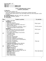
RECOMMENDED REPLACEMENT:
-Replace all posts, top rails, and mid rails with new in-kind ACZA 2.5 Retention (RET) treated No. 1 grade or higher lumber. Replace
all mounting bolts, washers, and nuts with new 316L/316 stainless steel hardware.
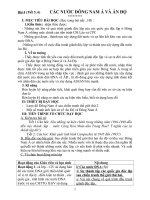
-Install, on both sides, stainless steel Type 316L 1.66 inch diameter handrail attached to top rail for all stairs to include E459
mounting brackets, round tube, termination 90 degree flat end, 45 degree angle coupling, and associated accessories as
distributed by Star Warehouse (www.stairwarehouse.com). Continue handrail for small landing at Pipeline Canal Bridge as shown
in photo on this page.
BID ITEM #3
STRUCTURAL MEMBERS TREATMENT RECOMMENDATIONS:
The Contractor shall add supplemental framing members to the structural system to accommodate the new fiberglass T-bar decking system. The T-bar fiberglass decking bearing (T) shall be installed perpendicular to the
existing and supplemental framing members, while the T-bar fiberglass crossing bars are parallel to the framing members. (See Component Replacement Schedule)
Bayou Coquille and Pipeline Canal Bridges, Stairs, and/or Landing
-Install three (3) new 2”x8”x16’-0”ACZA treated lumber No. 1 grade or higher with 2.5# retention (RET) between the existing, 4’-10” outside to outside, beams/stringers at approximately 1’-1 ¾” (13 ¾”) o.c. measuring from
the center of the 3” perimeter beam/stringer at 4’-7” o.c. (field verify). Cut new treated material, treat ends, and install between 3” by various size DB-1 or DB-2 glulam diaphragms. Contractor shall attached supplemental
joists with one Type III stainless steel angle bracket centered at each end. See Drawing Schedule sheet 11/15.
-The hot-dipped galvanized Sway Brace Rods at the Pipeline Bridge shall remain. Contractor shall field verify that 2”x8” can fit above the Sway Brace Rods before ordering material. Notching of the 2” material in this area may
be required. Do Not notch more than 50% of depth.
Bayou Coquille
-Replace two (2) ST-3 Stringers and provide Five (5) new ST-3 glulam 2.5# RET treated stringers (3”x18”x9’-8 9/6”). See Component Replacement Schedule and Drawing Schedule. Field verify dimensions before ordering.
JELA – 4/23/12
148819A - REPLACE BAYOU COQUILLE AND PIPELINE CANAL BRIDGES’ DECKING AND HANDRAILS SOW
BID ITEM DESCRIPTION OF WORK-5
BID ITEM #3 CONT.
-Replace two (2) ST-4 Stringers and provide Five (5) new ST-4 glulam 2.5# RET treated stringers (3”x18”x6’-11 1/6”). See Component Replacement Schedule and Drawing Schedule. Field verify dimensions before ordering.
-Replace eight (8) LB-1 (3”x10 ½”x5’-10”) in-kind with new ACZA 2.5# RET treated Douglas-fir No. 1 grade or higher.
-Replace four (4) bottom LB-2 (3”x10 ½”x9’-0”) in-kind with new ACZA 2.5# RET treated Douglas-fir No. 1 grade or higher.
Pipeline Canal
-Replace two (2) LB-1 (3”x10 ½”x5’-10”) with new LB-1A (3”x10 ½”x6’-8”) ACZA 2.5# RET treated Douglas-fir
No. 1 grade or higher. Members are located opposite of the Pipeline Canal bridge LB-3 members on the 12”
diameter wood piles.
-Replace four (4) LB-1 (3”x10 ½”x5’-10”), at ground by the each stair, in-kind with new ACZA 2.5# RET
treated Douglas-fir No. 1 grade or higher. Members are at first Wood Pile Bent for each stair staring run.
-Add at both pair of wood piles, two (2) horizontal 2”x8” bracing members, from salvaged (best from
removed top rails) or new, to the 3”x8” diagonal braces one at top and one at bottom (4 Total). Add so
that the horizontal members are facing each other between the pair of wood piles. Attach to west side of
the east wood piles and attach to the east side of the west wood piles. The COTR must approve all salvaged
material for quality assurance. If not approved the Contractor shall install new 2”x8” treated ACZA with 2.5
#RET.
-Use the salvaged Ledgers (LB-2) removed from Bayou Coquille, cut down to 3”x8” by length required (cut
top weathered side). Install salvaged material and spacer block with cut side down and treat all cut sides.
Pipeline Canal Observation Platform
-Install two (2) new 2”x8”x16’-0” ACZA treated lumber with 2.5# RET between the existing LJ-1 & LJ-2
3”x12” glulam end and intermediate 3’-7” o.c joists at approximately 1’-2 5/16” (14 5/16”) o.c. measuring
from the center of the 3” joists (field verify). Four (4) total supplemental joists both ends.
-Install two (2) new 2”x8”x16’-0” ACZA treated lumber with 2.5# RET between the remaining LJ-2 & LJ-3
3”x12” glulam intermediate 4’-0” o.c. joists at approximately 1’-4” (16”) o.c. measuring from the center of
the 3” joists (field verify). Eight (8) total supplemental joists required. Cut new treated material, treat ends,
and install between 3”x12” HD-1 Stringers. Contractor shall attached supplemental joists with one Type III
stainless steel angle bracket centered at each end. See Drawing Schedule sheet 11/15.
Replace all existing aluminum and galvanized hardware (all brackets, eyebolts, bolts, washers, nuts, etc.) at
stringers/beams, posts, and rails with new stainless steel material, Typical. See Drawing Schedule.
JELA – 4/23/12
148819A - REPLACE BAYOU COQUILLE AND PIPELINE CANAL BRIDGES’ DECKING AND HANDRAILS SOW
BID ITEM DESCRIPTION OF WORK-6
BID ITEM #4
EXISTING (July 1984) TREATMENT INFO:
Notes (SHT 12 AS-Built 467/41010B):
1.
2.
3.
4.
5.
6.
FABRICATED FROM WORM CCA TREATED LUMBER WITH 0.4# RET.
ROUGH SAWN FINISH
ARCHITECTURAL FINISH S&S
A.I.T.C STAMPED AND CERTIFIED
WATERPROOF ADHESIVE
NO FABRICATED STEEL OR HARDWARE FURNISHED BY FABRICATOR
SOUTHERN LAMINATORS, INC., DEHAM SPRINGS, LA
Glulam beam members, posts, and rails shall be replaced with ACZA treated lumber with 2.5# RET., including all railings and posts near Pipeline Canal Bridge east stairs and east platform area.
FABRICATION, MACHINING, CARE AFTER TREATMENT, AND FIELD TREATMENT
-Where possible, all fabrication and machining which cuts through the treating envelope shall be performed prior to treatment. The Contractor shall have the Laminator and/OR Lumber Mill make all cuts prior to treatment.
-When fabrication and machining are done after treatment, additional preservative treatment shall be applied in accordance with AWPA Standard M4, Standard for the Care of Preservative-Treated Wood Products.
-The application of oil or water-borne preservatives to treated or untreated members in the field is not as effective and cannot replace pressure preservative treatment; therefore, it is important to do as much machining prior
to treatment as possible. Cutting of treated material must be avoided whenever possible.
-Treated wood shall be protected from mechanical injury when handling. When handling damage occurs, or cuts, daps, or other machining is performed after treatment, the cut or damaged surfaces shall be field treated as
specified in AWPA Standard M4. All field fabrication, trimming, hole drilling, and surface damage should be sealed with a Copper Naphthenate.
-All treated wood products in this project shall be produced in compliance with the “Best Management Practices for the Use of Treated Wood in Aquatic and Other Sensitive Environments” (BMPs) published by the
“Supporting Organizations, November 1, 2011 or the most current version including published amendments.
-All treated wood in this project shall be certified by an independent third party inspection agency to have been produced in compliance with the BMPs.
Compliance will be documented by either Item A or B below:
A. Producers Participating in BMP Mark Program
The presence of the BMP Mark legibly stamped, branded, marked, end tagged or an equivalent designation on each piece of material or lot arriving on site.
Or
In lieu of placing the BMP Mark on each piece of material or lot, a certificate of compliance issued and signed by a WWPI qualified inspection agency (see discussion of BMP Mark Program below) certifying that the material
and/or its production was inspected in compliance with the “Quality Assurance Inspection Procedures for Best Management Practices for the Use of Treated Wood in Aquatic and Other Sensitive Environments”. The BMP
Mark shall be shown on the certificate of compliance.
B. Producers Not Participating in BMP Mark Program
A certificate of compliance issued and signed by an inspection agency certifying that the material and/or its production was inspected in compliance with the “Quality Assurance Inspection Procedures for Best Management
Practices for the Use of Treated Wood in Aquatic and Other Sensitive Environments”. An independent wood inspection agency of the Contractor’s choice and acceptable to the COTR can be used to provide the inspection
service.
JELA – 4/23/12
148819A - REPLACE BAYOU COQUILLE AND PIPELINE CANAL BRIDGES’ DECKING AND HANDRAILS SOW
BID ITEM DESCRIPTION OF WORK-7
BID ITEM #4 CONT.
Table 6. Retention Requirements (pcf) for Laminated Timber – Marine Applications (adapted from
AWPA U1-06, Commodity Specification G for solid-sawn materials in marine
applications)
USE CATEGORY
Preservative
Assay Zone
Penetration
Species
Creosote
ACZA
CCA
UC5A, UC5B, UC5C
Southern Pine, Mixed Southern
Pine
25
2.5
2.5
0 – 0.6 in.
2.5 in. or 85%
Ponderosa Pine
25
2.5
2.5
0 – 0.6 in.
2.5 in. or 85%
Coastal Douglas-fir
25
2.5
2.5(1)
0 – 0.6 in.
0.4 in. and 90%
Hem-Fir, Hem-Fir North
25
2.5
NR
0 – 0.6 in.
0.5 in. and 90%
(1) Coastal Douglas-fir from a few geographical areas has been found suitable for treatment with CCA, but it is generally
Recognized. Source: AMERICAN INSTITUTE OF TIMBER CONSTRUCTION (AITC) Standards for Preservative Treatment of Structural Glued Laminated Timbers
COATING TOP OF STINGERS/BEAMS SECTION:
-Clean and Prep surfaces to be coated. Ensure no mildew, dirt, or other containments reside of the areas to be treated. Clean to COTR satisfaction.
-The top of the following shall be treated with one application coat of a Copper Naphthenate sealer: Top of wood pilings that do not have felt paper, Top of all existing stringers/Beams/Ledgers/Diaphragms/etc., Top of new
stringers/Beams/Ledgers/Supplemental joists/etc. as needed, Top and vertical (riser) of Stair Stringers, and top of wood rails and Posts. Allow to dry and request inspection before continuing with next step.
-Apply West System Epoxy to top of all structural members excluding the rails and posts utilizing the resin, hardener, fillers, additives, etc. to achieve a water type seal. Install fiberglass rods and filler in repair holes created
from previous repairs. This shall be done by the Contractor and inspected by the COTR before the new decking system is installed.
JELA – 4/23/12
148819A - REPLACE BAYOU COQUILLE AND PIPELINE CANAL BRIDGES’ DECKING AND HANDRAILS SOW
BID ITEM DESCRIPTION OF WORK-8
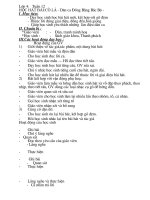
BID ITEM #5
Replace all existing bench material with new MS-T1215 Fiberglass Decking Units (BN-1) as seating and treated
ACZA 2.5 RET. glulam base BR-2 as structural support with three (3) per bench. Provide double 2”x6” blocking,
use best of handrail to be removed, beneath each base for structural support beneath the new deck floor. Cut
notch in floor to install new 316L stainless steel 1/4” x 3” wide x 8” plate with two horizontally centered holes 1”
from the top/bottom to be anchored to the base and blocking with one lag bolt each.
There shall be a total of 6 new benches located at the east and south section where the existing benches are
installed. BN-1 bench deck shall be 1 ½” tall by 24” wide by 4-0” length. The new Treated Glulam BR-2 base shall
be 3”thick by 16” tall by 2’-0 wide treated glulam.
Provide shop drawings of the bench system based on information provided for approval by the COTR.
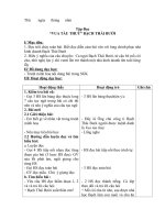
Replacement hand rail shall be installed per the original/existing design. Field verify dimension so the seating
starts at/near bottom of mid-rail as shown in photos.
JELA – 4/23/12
148819A - REPLACE BAYOU COQUILLE AND PIPELINE CANAL BRIDGES’ DECKING AND HANDRAILS SOW
BID ITEM DESCRIPTION OF WORK-9
DRAWING SCHEDULE
Provided in this attached section is the 1984 as-constructed drawings of the bridge project. The contractor shall field verify all dimensions as not all as-constructed information on the drawings was changed to reflect actual
conditions. See the following pages for project reference.
JELA – 4/23/12
148819A - REPLACE BAYOU COQUILLE AND PIPELINE CANAL BRIDGES’ DECKING AND HANDRAILS SOW
BID ITEM DESCRIPTION OF WORK-10