Fpga realization of forward kinematics and inverse kinematics for five axis articulated robot arm
Bạn đang xem bản rút gọn của tài liệu. Xem và tải ngay bản đầy đủ của tài liệu tại đây (3.79 MB, 135 trang )
..
Southern Taiwan University of Science and
Technology
Graduate School of Electrical Engineering
Ph.D. Dissertation
FPGA Realization of Forward Kinematics and
Inverse Kinematics for Five-Axis Articulated
Robot Arm
Graduate Student: Bui Thi Hai Linh
Advisor:Ying-Shieh Kung
July, 2015
i
Acknowledgments
I would like to express my deepest gratitude to all of my teachers in Department of
Electrical Engineering-Southern Taiwan University, especially Prof. Ying-Shieh Kung for
his patience and guidance throughout my research since 2009 when I study the Master
degree until now when I study the Doctoral degree. His guidance and inspiration have
provided an invaluable experience that will help me in my career.
I would also like to thank my lab-mates for their help and advice. They are also the
people who make me have unforgettable time and sweet memories in Taiwan.
Finally, I am grateful to my family for their constant love and support, and
encouragement.
ii
Abstract
This dissertation presents a study of the forward and inverse kinematics for a fiveaxis articulated robot arm based on Field Programmable Gate Array (FPGA) technology.
Some trigonometric functions using Look-Up Table (LUT) and Taylor series method are
used in hardware implementation to speed up of tracking the motion trajectories applied for
forward kinematics and invers kinematics for five-axis articulated robot arm. Firstly, the
forward kinematics and inverse kinematics of five-axis articulated robot arm are derived.
Secondly, the computations algorithms and its hardware implementation are described.
Thirdly, Very high speed integrated circuits Hardware Description Language (VHDL) is
applied to describe the overall hardware behavior of forward and inverse kinematics.
Additionally, Finite State Machine (FSM) is applied for reducing the hardware resource
usage. Further, to verify the correctness of the forward and inverse kinematics for five-axis
articulated robot arm, a co-simulation work is constructed by Modelsim and Matlab
Simulink. The forward and inverse kinematics hardware is run by Modelsim and a test
bench which generates stimulus to Modelsim and displays the output response that is taken
in Simulink. Under this design, the combination of the forward and inverse kinematics
simulation for tracking the motion trajectories is adopted. Fourthly, the design of forward
and inverse kinematics IPs for five-axis robot arm is implemented by a single FPGA.
Additionally, a Nios II processor can be embedded into FPGA to construct a System on a
Programmable Chip (SoPC) developing environment. Programs in Nios II processor are
coded in C language and IPs digital hardware is described by VHDL. The Man-Machine
Interface (MMI) developed by Visual Basic language which displays the results of
computations kinematics in FPGA into decimal number for easy checking the correctness
of results. Therefore, the digital hardware/software co-design based on the SoPC is suitable
for the development of the forward and inverse kinematics for five-axis articulated robot
arm. Finally, an experiment system has been built up as well as some experimental results
have been demonstrated to verify the effectiveness and correctness of computations for
forward and inverse kinematic which is applied to the real five-axis articulated robot arm.
iii
摘要
本文基於 FPGA(現場可程式邏輯閘陣列)技術提出了前向和逆向運動學的五
軸模組化機械臂之研究。首先,推導五軸關節型機械手臂的前向運動學和逆向運動
學。其次,針對演算法和硬體實現進行了描述。第三,超高速積體電路硬體描述語
言(VHDL)被用於描述前向和反向運動學的整體硬體行為。此外,運用有限狀態機
器(FSM)以減少硬體資源的使用。為了驗證五軸關節型機械手臂的前向和逆向運
動學的正確性,將結合 Modelsim 和 Matlab Simulink 進行模擬。前向和逆向運動學的
硬體是由 Modelsim 執行,而 Modelsim 測試平台產生的輸入訊號及輸出響應將顯示
在 Simulink 中。根據這樣的設計,前向及逆向運動學及運動軌跡追蹤可以在數微秒
內完成。第四,五軸機械臂的前向和逆向運動學 IP 設計將由單顆 FPGA 實現。此
外,Nios II 處理器可以嵌入到 FPGA 中以建構 SoPC(在系統可編程片)開發環境。
在 Nios II 處理器的應用程式以 C 語言撰寫,而 VHDL 將用於描述前向和逆向運動學
的數位硬體電路。另外,本論文也利用 visual basic 開發一套人機介面(MMI) ,此將
呈現前向和逆向運動學 IP 計算後的結果。因此,基於所述,SoPC 將適合發展五軸機
械手臂的前向和逆向運動學的硬體/軟體共同設計環境。最後,將建立一個實驗系統
並有實驗結果來證實應用於五軸模組化機械手臂的前向及逆向運動學計算的有效性
和正確性。
Table of Content
Acknowledgments ................................................................................................................................ i
Abstract ............................................................................................................................................. iii
摘要.................................................................................................................................................... iv
Table of Content................................................................................................................................. iv
List of Figures ................................................................................................................................... vii
iv
List of Tables ...................................................................................................................................... x
List of Symbols .................................................................................................................................. xi
Chapter 1 Introduction .................................................................................................................... - 1 1.1 Research background & literature survey ............................................................................. - 1 1.2 The motivation of the study .................................................................................................. - 6 1.3 The structure of thesis ........................................................................................................... - 7 Chapter 2 Mathematical description of kinematics and motion trajectories planning .................... - 8 2.1 Introduction of five-axis articulated robot arm ..................................................................... - 8 2.2 Review of kinematics .......................................................................................................... - 10 2.2.1 Rotating coordinate system .......................................................................................... - 12 2.2.2 Homogeneous coordinates ........................................................................................... - 13 2.2.3 Coordinates architecture............................................................................................... - 15 2.2.4 Rotary joint coordinates architecture ........................................................................... - 16 2.3 Robot kinematics of five-axis articulated robot arm ........................................................... - 18 2.3.1 Forward kinematics ...................................................................................................... - 20 2.3.2 Inverse kinematics ........................................................................................................ - 24 2.4 The computation of point-to-point motion control ......................................................... - 29 2.4.1 Five axes trajectory planning ....................................................................................... - 32 2.4.2 The formulas of motion trajectories ............................................................................. - 33 2.4.2.1 Linear motion trajectory ........................................................................................ - 34 2.4.2.2 Circular motion trajectory ..................................................................................... - 34 2.4.2.3 Star motion trajectory ............................................................................................ - 35 2.4.2.4 Window motion trajectory .................................................................................... - 36 Chapter 3 Hardware implementation of forward kinematics and inverse kinematics................... - 38 3.1 Introduction and literature review ....................................................................................... - 38 3.2 Review of VHDL and Q-format design .............................................................................. - 42 3.3 An example of Sum of Product ........................................................................................... - 44 3.4 Trigonometric functions ...................................................................................................... - 48 3.4.1 Computation algorithm of Sine and Cosine functions.................................................. - 49 3.4.2 Computation algorithm of Arctangent function using Taylor series expansion........... - 50 3.4.3 Computation of Arccosine function using Taylor series expansion method ................ - 54 3.5 Design of hardware implementation for forward kinematics and inverse kinematics ........ - 56 3.5.1 Forward kinematics and inverse kinematics design in VHDL using Q-format ........... - 56 v
3.5.2 FSM for forward kinematics and inverse kinematics ................................................... - 57 Chapter 4 Modelsim/Simulink co-simulation of forward/inverse kinematics for five-axis articulated
robot arm ....................................................................................................................................... - 63 4.1 Introduction of Modelsim/Simulink co-simulation ............................................................. - 63 4.2 Co-Simulation cases using Modelsim/ Simulink ................................................................ - 67 4.2.1 Sum of Product simulation results ............................................................................... - 68 4.2.2 Sine and cosine functions co-simulation results .......................................................... - 69 4.2.3 Arctangent and arccosine functions co-simulation results ........................................... - 72 4.3 Modelsim/Simulink co-simulation of forward/inverse kinematics ..................................... - 74 4.4 Simulation results in Modelsim/Simulink of tracking motion trajectories ......................... - 79 4.4.1 Linear motion trajectory ............................................................................................... - 81 4.4.2 Circular motion trajectory ............................................................................................ - 82 4.4.3 Star motion trajectory................................................................................................... - 82 4.4.4 Window motion trajectory ........................................................................................... - 85 Chapter 5 FPGA realization of forward/inverse kinematics for five-axis articulated robot arm .. - 88 5.1 Introduction ......................................................................................................................... - 88 5.2 Description of SoPC builder design .................................................................................... - 89 5.2.1 DE2 115 board ............................................................................................................. - 89 5.2.2 Nios II embedded processor ......................................................................................... - 92 5.3 FPGA implementation of forward kinematics and inverse kinematics ............................... - 95 5.4 Applying to real robot arm .................................................................................................. - 98 5.4.1 Hardware implementation system .............................................................................. - 100 5.4.1.1 CAN bus interface ............................................................................................... - 100 5.4.1.2 Overall hardware system ..................................................................................... - 102 5.4.2 Experimental results ................................................................................................... - 104 5.4.2.1 Linear motion trajectory ...................................................................................... - 105 5.4.2.2 Circular motion trajectory ................................................................................... - 106 5.4.2.3 Star motion trajectory .......................................................................................... - 106 5.4.2.4 Window motion trajectory .................................................................................. - 107 Chapter 6 Conclusion and future works ...................................................................................... - 112 6.1 Conclusion ........................................................................................................................ - 112 6.2 Future works ..................................................................................................................... - 113 References ................................................................................................................................... - 114 vi
Biography .................................................................................................................................... - 122 Academic Publications ................................................................................................................ - 123 -
List of Figures
Figure 2.1 Electrical · Rotary Actuators · Universal Rotary Actuators .......................................... - 9 Figure 2.2 The sectional diagram .................................................................................................... - 9 Figure 2.3 The five-axis articulated robot arm.............................................................................. - 10 Figure 2.4 The definition of standard Denavit-Hartenberg link parameters [37] ......................... - 11 Figure 2.5 The end-effector ........................................................................................................... - 13 Figure 2.6 The coordinate architecture ......................................................................................... - 16 Figure 2.7 The location of three-vectors n, o, a ............................................................................ - 16 Figure 2.8 Robot coordinates indicate .......................................................................................... - 17 Figure 2.9 The relationship coordinates between two joints ......................................................... - 17 Figure 2.10 The schematic representation of forward and inverse kinematics ............................. - 19 Figure 2.11 The link coordinate system of a five-axis articulated robot arm (general) ................ - 19 Figure 2.12 The link coordinate system of a five-axis articulated robot arm (details) ................. - 20 Figure 2.13 The base and first link coordinate schematic ............................................................. - 21 Figure 2.14 The first link and the second link coordinate schematic ............................................ - 21 vii
Figure 2.15 The sencond link and the third link coordinates schematic ....................................... - 22 Figure 2.16 The third link and the fouth link coordinates schematic ............................................ - 22 Figure 2.17 The fifth link and the fouth link coordinates schematic ............................................ - 23 Figure 2.18 LFPB trajectory (a) velocity; (b) acceleration ........................................................... - 31 Figure 2.19 Minimum-time trajectory (a) velocity; (b) acceleration ............................................ - 32 Figure 2.20 Circular motion trajectory tracking............................................................................ - 34 Figure 2.21 Star motion trajectory tracking .................................................................................. - 36 Figure 2.22 Window motion trajectory tracking ........................................................................... - 37 Figure 3.1 Parallel processing using three multipliers and two adders execute by one step ......... - 46 Figure 3.2 Sequential processing using one multiplier and one adder execute by five step ......... - 47 Figure 3.3 VHDL code for computing the sum of product ........................................................... - 47 Figure 3.4 Three cases for computing the sum of product ............................................................ - 48 Figure 3.5 FSM for computing the sine function .......................................................................... - 49 Figure 3.6 FSM for computing the cosine function ...................................................................... - 50 Figure 3.7 Compute a tan 2( y / x ) of each region in X-Y coordinates................................. - 52 Figure 3.8 The diagram to compute a tan 2( y / x ) function ........................................................ - 53 1
Figure 3.9 FSM to compute tan ( x) function ........................................................................... - 53 Figure 3.10 Computing range of cos 1 ( x) ........................................................................... - 54 Figure 3.11 Hardware implementation diagram for arccosine function ....................................... - 55 1
Figure 3.12 FSM for computing the cos ( x) function (range from 450 to 900) ....................... - 56 Figure 3.13 Block diagram for (a) forward kinematics and (b) inverse kinematics...................... - 57 Figure 3.14 FSM for computing the Forward kinematics ............................................................. - 60 Figure 3.15 FSM for computing the Inverse kinematics .............................................................. - 61 Figure 3.16 Forward kinematics computations time in FPGA ...................................................... - 62 Figure 3.17 Inverse kinematics computations time in FPGA ....................................................... - 62 Figure 4.1 Project flow .................................................................................................................. - 66 Figure 4.2 Simulation flow working library.................................................................................. - 67 Figure 4.3 Modelsim co-simulation of Sum of Product with 16bit Q0......................................... - 68 Figure 4.4 Modelsim co-simulation of Sum of Product with 16bit Q15....................................... - 69 Figure 4.5 Modelsim co-simulation of Sum of Product with 16bit Q24....................................... - 69 Figure 4.6 The co-simulation in Modelsim/Simulink of Sine function......................................... - 71 Figure 4.7 The co-simulation in Modelsim/Simulink of Cosine function ................................... - 71 Figure 4.8 The co-simulation in Modelsim/Simulink of Arctangent function .............................. - 73 Figure 4.9 The co-simulation in Modelsim/Simulink of Arccosine function................................ - 73 Figure 4.10 Setting complier ......................................................................................................... - 75 Figure 4.11 Setting the “220pack.vhd” and “220model.vhd” compile to library “lpm” .............. - 75 Figure 4.12 Compiled all files successfully and run Modelsim .................................................... - 76 Figure 4.13 Co-simulation architecture of forward kinematics using Modelsim/Simulink .......... - 76 Figure 4.14 Co-simulation architecture of inverse kinematics using Modelsim/Simulink ........... - 77 Figure 4.15 Forward kinematics and Inverse kinematics co-simulation in Modelsim/Simulink .. - 80 viii
Figure 4.16 The results of linear motion trajectory co-simulation in Modelsim/Simulink ........... - 81 Figure 4.17 Error of linear motion trajectory co-simulation in Modelsim/Simulink .................... - 82 Figure 4.18 The results of circular motion trajectory co-simulation in Modelsim/Simulink ........ - 83 Figure 4.19 Error of circular motion trajectory co-simulation in Modelsim/Simulink ................ - 83 Figure 4.20 The results of star motion trajectory co-simulation in Modelsim/Simulink ............. - 84 Figure 4.21 Error of star motion trajectory co-simulation in Modelsim/Simulink ...................... - 84 Figure 4.22 The results of window motion trajectory simulation in Modelsim/Simulink ........... - 85 Figure 4.23 Error of window motion trajectory simulation in Modelsim/Simulink .................... - 86 Figure 5.1 The architecture system of hardware implementation ................................................. - 89 Figure 5.2 The DE2-115 board (top view) [76] ............................................................................ - 91 Figure 5.3 The Nios embedded processor ..................................................................................... - 92 Figure 5.4 The Nios Development Tool Flow .............................................................................. - 93 Figure 5.5 A Nios II system implemented on the DE2 board [76] ............................................... - 94 Figure 5.6 Embedded components information flow .................................................................... - 95 Figure 5.7 Architecture of forward kinematics IP and inverse kinematics IP base on FPGA ...... - 96 Figure 5.8 Design of forward kinematics IP, inverse kinematics IP and Nios II processor .......... - 97 Figure 5.9 Nios II IDE environments ............................................................................................ - 97 Figure 5.10 The man-machine interface programmed in Visual Basic......................................... - 98 Figure 5.11 Five-axis articulated robot arm by PowerCube ......................................................... - 99 Figure 5.12 CAN-bus adaptor ..................................................................................................... - 100 Figure 5.13 Block-circuit diagram of CAN-USB-Mini module ................................................. - 101 Figure 5.14 Physical Connection for CAN bus [77] ................................................................... - 102 Figure 5.15 Block of system architecture ................................................................................... - 103 Figure 5.16 Five-axis articulated robot arm and MMI ................................................................ - 104 Figure 5.17 The feedback of window motion trajectory on MMI .............................................. - 104 Figure 5.18 The tracking response of linear motion trajectory by PowerCube robot arm .......... - 105 Figure 5.19 Tracking error of linear motion trajectory ............................................................... - 106 Figure 5.20 The tracking response of circular motion trajectory by PowerCube robot arm ....... - 107 Figure 5.21 Tracking error of circular motion trajectory ............................................................ - 108 Figure 5.22 The tracking response of star motion trajectory by PowerCube robot arm ............. - 108 Figure 5.23 Tracking error of star motion trajectory .................................................................. - 109 Figure 5.24 The tracking response of window motion trajectory by PowerCube robot arm ...... - 109 Figure 5.25 Tracking error of window motion trajectory ........................................................... - 110 -
ix
List of Tables
Table 2.1 Denavit-Hartenberg parameters;their physical meaning, symbol and formaldefinition- 12 Table 2.2 Denavit-Hartenberg parameters .................................................................................... - 20 Table 4. 1The co-simulation Modelsim and Matlab Simulink of Sine function ........................... - 72 Table 4.2 The co-simulation Modelsim/Simulink of Cosine function .......................................... - 72 Table 4.3 The evaluation results for arctangent function ............................................................. - 74 Table 4.4 The evaluation results for arccosine function ............................................................... - 74 Table 4.5 Two cases simulation results of inverse kinematics from Modelsim and Matlab......... - 78 Table 4.6 Two cases simulation results of forward kinematics from Modelsim and Matlab ....... - 78 Table 4.7 Mean square error of simulation results ........................................................................ - 87 Table 5.1 The datasheet of PowerCube modules type .................................................................. - 99 Table 5.2 Mean square error of experimental results .................................................................. - 110 -
x
List of Symbols
A
Acceleration/deceleration value
ai
The distance between the zi-1 and zi axes along the xi axis
i
The angle from zi-1 axis to the zi axis about the xi axis
di
The distance from the origin of frame i-1 to the xi axis along the zi-1 axis
Δ
Angle increment
i
Angle at point
γ
Angle between z-axis and path vector
N
The interpolation number
q*p
Acceleration region
xi
q i
The instantaneous position command
R
Radius
S
Running speed
Δs
Path increment
T
Running time
Tacc
Acceleration period
t
Period sampling time
td
Position command sampling interval
tm
Blend time
ts
Desired parameter
i
The angle between the xi-1 and xi axes about the zi-1 axis
i
Moving displacement
v(t)
Velocity
vm
The maximum velocity
Wi
The maximum velocity
x(t)
Desired position
xm
Command position
xi(tk
The desired values of that variable at the discrete times tk
xi
Command of x-axis motion trajectory
yi
Command of y-axis motion trajectory
zi
Command of z-axis motion trajectory
xii
Chapter 1 Introduction
1.1 Research background & literature survey
Robotics is the branch of mechanical engineering, electrical engineering and
computer science that deals with the design, construction, operation, and application of
robots as well as computer systems for their control, sensory feedback, and information
processing [1]. Robotic control is currently an exciting and highly challenging research
focus. Several solutions for implementing the control architecture for robots have been
proposed in literature. The common industrial manipulator is often referred to as a robot
arm, with links and joints described in similar terms. Manipulators which emulate the
characteristics of a human arm are called articulated arms [2].
An articulated robot is a robot which is fitted with rotary joints. Rotary joints allow a
full range of motion, as they rotate through multiple planes, and they increase the
capabilities of the robot considerably. An articulated robot can have one or more rotary
joints, and other types of joints may be used as well, depending on the design of the robot
and its intended function. With rotary joints, a robot can be engaged in very precise
movements. Articulated robots commonly show up on manufacturing lines, where they
utilize their flexibility to bend in a variety of directions. Multiple arms can be used for
greater control or to conduct multiple tasks at once, for example, and rotary joints allow
robots to do things like turning back and forth between different work areas.
These robots can also be seen at work in labs and in numerous other settings.
Researchers developing robots often work with articulated robots when they want to be
engaged in activities like teaching robots to walk and developing robotic arms. The joints in
the robot can be programmed to interact with each other in addition to activating
independently, allowing the robot to have an even higher degree of control. Many next
generation robots are articulated because this allows for a high level of functionality.
Basic articulated robots are sometimes available in robotics kits, allowing people who
are just starting to explore robotics to play with rotary joints and to get a feel for how they
operate. More sophisticated robots may be built for a special purpose by robotics experts
-1-
who design every component of the articulated robot from the ground up. Robots used on
assembly lines and in similar settings are produced in various quantities by companies
which develop manufacturing [3].
Modular robot arms are kinematic chains consisting of identical modules which can
be easily assembled or disassembled. This gives the users control of the number of joints
(or the number of degrees of freedom) in the arm by simply adding or subtracting modules.
Most modular robot arms are also reconfigurable, meaning that the user also has flexibility
in the orientation of each module. This gives the user the ability to change the shape of the
arm and the workspace (or reach) of the end-effector. A modular robot arm that is not
reconfigurable would be restricted to movement in a single plane, which would make it
unsuitable for most applications of modular robot arms. Modular, reconfigurable robots
have found applications wherever a robot arm with many degrees of freedom is needed,
such as when the robot arm is expected to reach around an object or manoeuvre itself into a
confined space such as a pipe, duct, or small compartment. Currently, there are three
suppliers for such robots: Amtec, Schunk, and OC Robotics. Amtec offers its “PowerCube”
line of modules for modular and reconfigurable robots. These modules consist of two cubes,
one cube being a servo motor while the other being a gearbox. Schunk also offers modular
and reconfigurable robots. In Schunk’s robots, the modules are not the same size (e.g. the
lower modules are larger than the upper ones). OC Robotics is the only commercial
supplier of snake-arm robots, which are capable of continuous curvature. Their robots work
by attaching three cables to the top of each module and adjusting the tension in the cables
in order to position the modules.
In the past, a major obstacle in the development of service robots suitable for series
production was the price. Robot solutions were too expensive even for high-end users. A
clear potential for development is currently emerging particularly in the Schunk’s modular
mechatronic systems. In contrast to initial series production trials in Asia and the USA,
which used cheap components for the mass market, Schunk’s industrial-quality components
make it a partner in the development of production-ready service robotics solutions in the
commercial research area. An enormous store of modules permits high-quality solutions to
be constructed in modular form at comparative costs. Schunk’s PRL servo-electric rotary
-2-
actuator enables the creation of reconfigurable modular robot structures. The individual
PRL modules can be assembled with complete freedom and flexibility using connecting
parts to produce an individual lightweight arm. The rotary actuator is set in motion by a
brushless servo-motor with Harmonic Drive transmission, already incorporated with the
complete power and control electronics. It is capable of positioning moves with ramp
control and features monitoring of the end positions, voltage, current and temperature.
Thanks to the use of lightweight, high-strength materials, the compact rotary actuators
achieve a weight/payload ratio exceeding 2:1. The power supply, control elements and
universal communication interfaces are already integrated. Integrated and open: thanks to
the use of quill drives in the interior of the arm, all wiring as far as the pan-tilt unit, or
“wrist”, is done internally. There are no visible cables and no interfering contours. The
internally routed CAN bus and the open software architecture means that every kind of
terminal device can be connected to and operated from the pan-tilt unit of the arm. For
maximum flexibility, the light-weight arm can also be battery-operated. Control is done
directly via PC or notebook (PCI or USB interface). Moreover, an external robot controller
is not required. The rotary module product line from Schunk offers a complete spectrum of
compact swivel and rotary units for every handling task – and for fast and easy integration.
Internal media feed-through guarantees reliable performance and minimizes interference
contours. Various sensor monitoring capabilities and multiple mounting options for all
modules increases the flexibility during plant engineering. Modular joint design and
precision design problems which aims for mapping the dual-arm robot to realize high
maneuverability and precision, has been a research topic in recent years. A typical modular
joint design is the third generation of the DLR (German Aerospace Center in Germany)
robot arm , it make the motor, brake, harmonic reducer and various sensors integrated in
the joint, and the development of new motor greatly improved motor performance and with
improved brake reduce the weight of the joints [4].
Robot control system has three categories, including distributed control using upper
and lower machine two distributed architecture. Distributed control systems of the various
subsystems are independent and have the same functionality. It has outstanding advantages:
modularity, substitutability, timeliness, scalability. These features are consistent with the
-3-
requirements of modular joints, so we chose a distributed control. A distributed control
system, CAN bus is a kind of effective support distributed serial communication network,
so joint control interface using CAN bus.
Kinematics studies the motion of bodies without consideration of the forces or
moments that cause the motion. Robot kinematics refers to the analytical study of the
motion of a robot arm. Formulating the suitable kinematics models for a robot mechanism
is very crucial for analyzing the behavior of industrial robot arms. There are mainly two
different spaces used in kinematics modeling of robot arm namely, Cartesian space and
Quaternion space. The transformation between two Cartesian coordinate systems can be
decomposed into a rotation and a translation. The robot kinematics can be divided into
forward kinematics and inverse kinematics. Forward kinematics problem is straightforward
and there is no complexity deriving the equations. Hence, there is always a forward
kinematics solution of an arm. Inverse kinematics is a much more difficult problem than
forward kinematics [5]. The solution of the inverse kinematics problem is computationally
expansive and generally takes a very long time in the real time control of robot arm.
Singularities and nonlinearities that make the problem more difficult to solve. A. Bajo et al.
[16] proposed a novel kinematic-based framework for collision detection and estimation of
contact location along multisegment continuum robots in 2012. L. Sciavicco [17] presented
a solution algorithm for the inverse kinematic problem for robotic manipulators whose
three end effector revolute joint axes intersect two-by-two in 1986. In 2009, G. Antonelli et
al. [8] provided a convergence analysis of classical inverse kinematics algorithms for
redundant robots. S. Kucuk et al. [5] proposed an Inverse Kinematics Solutions of
Fundamental Robot Manipulators with Offset Wrist in 2006. In 2008, V. Ruiz de Angulo [9]
adopted a technique to speed up the learning of the inverse kinematics of a robot
manipulator by decomposing it into two or more virtual robot arms.
For the progress of Very Large Scale Integration (VLSI) technology, the Field
Programmable Gate Arrays (FPGAs) has been widely investigated due to their
programmable hard-wired feature, fast time-to-market, shorter design cycle, embedding
processor, low power consumption and higher density for the implementation of the digital
system. FPGA provides a compromise between the special-purpose Application Specified
-4-
Integrated Circuit (ASIC) hardware and general-purpose processors. In 1998, Kabuka [10]
applied two high performance floating-point signal processors and a set of dedicated
motion controllers to build a control system for a six-joint robots manipulator. Yasuda [11]
adopts a PC-based microcomputer and several PIC microcomputers to construct a
distributed motion controller for mobile robots. Li et al. [12] in 2003 utilized an FPGA
(Field Programmable Gate Array) to implement autonomous fuzzy behavior control on
mobile robot. Oh et al. [13] (2003) present a DSP (Digital Signal Processor) and a FPGA to
design the overall hardware system in controlling the motion of biped robots. C.C. Wong
[14] presents a FPGA realization structure based on CORDIC is proposed to implement
inverse kinematics for a biped robot in 2013. Sanchez, D.F et al. [15] adopted an FPGA
Implementation for Direct Kinematics of a Spherical Robot Manipulator in 2009. A neural
network (NN)-based inverse kinematics problem of redundant manipulators subject to joint
limits is presented by Assal, S.F.M. et al. [16] in 2006 Tchon, K. et al. [17] proposed an
Optimal Extended Jacobian Inverse Kinematics Algorithms for Robotic Manipulators in
2008. Ben-Gharbia, K.M. presented a method for identifying all the kinematic designs of
spatial positioning manipulators that are optimally fault tolerant in a local sense et al. [18]
in 2013. Yi Min Zhao et al. [19] proposed an algorithm for the accurate path tracking of
industrial robots in 2015. Ying-Shieh Kung et al. [20] adopted an implementation of
inverse kinematics and servo controller for robot manipulator using FPGA in 2006.Based
on ARM Processor and FPGA Co-processor, kinematics control for a 6-DOF (Degree of
Freedom) space manipulator is realized by Zheng Yili et al. [21] in 2008. Gac, K. et al. [22]
presented an application of field programmable gate arrays (FPGA) to support the
calculation of the inverse kinematics problem of a parallel robot in 2012. Boyin Ding et
al.[23] adopted a hexapod robotic test system has been developed to enable complex six
degree of freedom (6-DOF) testing of bones, joints, soft tissues, artificial joints and other
medical and surgical devices in 2011. Ching-Chih Tsai et al. [24] presented a coarse-grain
parallel deoxyribonucleic acid (PDNA) algorithm for optimal configurations of an
omnidirectional mobile robot with a five-link robotic arm in 2011. However, these methods
only adopt PC-based microcomputer or the DSP chip to realize the software part or adopt
the FPGA chip to implement the hardware part of the robotic control system. They do not
-5-
provide an overall hardware/software solution by a single chip in implementing the motion
control architecture of robot system.
Hence, many practical applications in industrial control [25], multi-axis motion
control [26] and robotic control [14-20] have been studied. Therefore, for speeding up the
computational power, the forward and inverse kinematics based on VHDL is studied in this
dissertation. And the VHDL is applied to describe the overall behavior of the forward and
inverse kinematics.
1.2 The motivation of the study
The kinematics problem is an important study in the robotic motion control. The
mapping from joint space to Cartesian task space is referred to as forward kinematics and
mapping from Cartesian task space to joint space is referred to as inverse kinematics [2].
Because of the complexity of inverse kinematics, it is usually more difficult than forward
kinematics to find the solutions [27-30]. In addition, when the robot arm executes a motion
control, the complicated inverse kinematics computation consumes much CPU time and it
certainty slows down the motion performance of robot arms. Therefore, solving the
problem of implementation of forward kinematics and inverse kinematics becomes an
important issue.
For the progress of Very Large Scale Integration (VLSI) technology, the Field
Programmable Gate Arrays (FPGAs) has been widely investigated due to their
programmable hard-wired feature, fast time-to-market, shorter design cycle, embedding
processor, low power consumption and higher density for the implementation of the digital
system. FPGA provides a compromise between the special-purpose Application Specified
Integrated Circuit (ASIC) hardware and general-purpose processors. In recent years, an
Electronic Design Automation (EDA) Simulator Link, which can provide a co-simulation
interface between MALTAB/Simulink [31] and HDL simulators-Modelsim [32], has been
developed and applied of design the control system [32-33]. Using it you can verify a
VHDL, Verilog, or mixed-language implementation against your Simulink model or
MATLAB algorithm. In MATLAB/Simulink environment, it can generate stimuli to
Modelsim and analyze the simulation’s responses [31].
-6-
In this dissertation, a co-simulation by EDA Simulator Link is applied to the
proposed forward kinematics and inverse kinematics hardware. Some simulation results
based on EDA Simulator Link will demonstrate the correctness and effectiveness of the
forward and inverse kinematics. Furthermore, an experiment system has been set up as
expect to some simulations and experimental results; it has demonstrated to verify the
effectiveness and correctness of the proposed FPGA-based on computations of forward
kinematics and inverse kinematics IPs which is applied to five-axis articulated robot arm by
Power Cube via CAN-bus interface to display the results on MMI successfully.
1.3 The structure of thesis
The dissertation is divided into six chapters. The outlines of chapters are as follow
Chapter 1: Introduction
Chapter 2: The mathematical description of the kinematics and motion trajectory planning
Chapter 3: Hardware implementation of forward kinematics and inverse kinematics
Chapter 4: Modelsim/Simulink co-simulation of forward/inverse kinematics for five-axis
articulated robot arm
Chapter 5: FPGA-realization of forward/inverse kinematic for five-axis articulated robot
arm
Chapter 6: Conclusion and future works.
-7-
Chapter 2 Mathematical description of kinematics
and motion trajectories planning
This chapter presents the mathematical description of the forward kinematics and
inverse kinematics and its motion trajectory planning for five-axis articulated robot arm.
2.1 Introduction of five-axis articulated robot arm
A robot manipulator is an electronically controlled mechanism, consisting of
multiple segments, that performs tasks by interacting with its environment. They are also
commonly referred to as robotic arms. All their joints are rotary (or revolute). A
representative articulated robot is Power Cube Modular robot.
Simulation and Control of Reconfigurable Modular Robot Arm Based on Close
Loop Real-Time Feedback by Jun Zhou [34] in 2010. R.Wei et al. [35] adopted a
Distributed Hardware-in-the-Loop Simulation for Space Robot on CAN Bus in 2006.
The rotary module product line from SCHUNK offers a complete spectrum of
compact swivel and rotary units for every handling task – and for fast and easy integration.
Internal media feed-through guarantees reliable performance and minimizes interference
contours. Various sensor monitoring capabilities and multiple mounting options for all
modules increases the flexibility during plant engineering. Strong arguments for rotary
modules from SCHUNK: Short swiveling times, continuously adjustable end positions,
Lockable intermediate position, Fast and easy integration, Pneumatic, electric or hydraulic
[4].
The rotary actuator is equipped with a Harmonic Drive precision gear, which is
driven directly by a brushless DC servo-motor. The PRL rotary actuator is electrically
actuated by the fully integrated control and power electronics. In this way, the module does
not require any additional external control units. A varied range of interfaces, such as
Profibus DP, CAN-Bus or RS-232 are available as methods of communication. This
enables you to create industrial bus networks, and ensures easy integration in control
systems. You can make use of our hybrid cables for conveying the supply voltage and for
communication. If you wish to create combined systems (e.g. a rotary gripping module),
-8-
various other modules from our PowerCube series are at your disposal. The position of the
motor shaft is always shown in the drawing in the zero position (0°). From here, it can be
rotated clockwise and anti-clockwise. The turning range may exceed 360° several times,
depending on the type of application. After switching on the module reports its position as
an absolute value (last position before switch off). Swiveling times are purely the times of
the output cube to rotate from rest position to rest position. Relay switching times or SPC
reaction times are not included in the above times and must be taken into consideration
when determining cycle times. Load-dependent rest periods may have to be included in the
cycle time [4].
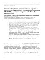
Figure 2.1 Electrical · Rotary Actuators · Universal Rotary Actuators
○
1 Complete performance
and control electronics
○
2 Integrated brake
○
3 Brushless servo-motor
○
4 Harmonic Drive® gear
Figure 2.2 The sectional diagram
Fig.2.1 shows the five-axis articulated robot arm PowerCube by Schunk Company,
Germany. The sectional diagram in the Fig.2.2 shows the modular contains of parts inside.
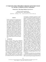
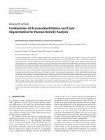
The five-axis articulated robot arm applied by five modules is shown in the Fig.2.3.
-9-
Figure 2.3 The five-axis articulated robot arm
2.2 Review of kinematics
The study of robot arm involves dealing with the positions and orientations of the
several segments that make up the arm. This module introduces the basic concepts that are
required to describe these positions and orientations of rigid bodies in space and perform
coordinate transformations. In order to make the end-effector of robot arm can be more
accurate to reach the target, firstly, carry on forward kinematics and inverse kinematics to
find out the solution. It is an important issue to control the robot arm using the kinematics.
Forward kinematics is the method for determining the orientation and position of the end
effector, given the joint angles and link lengths of the robot arm. Inverse kinematics is the
opposite of forward kinematics. This is when you have a desired end effector position, but
need to know the joint angles required to achieve it [36].
There are many ways to represent rotation, including the following: Euler angles,
Gibbs vector, Cayley-Klein parameters, Pauli spin matrices, axis and angle, orthonormal
matrices,
and
Hamilton’s
quaternions.
Of
these
representations,
homogenous
transformations based on 4x4 real matrices (orthonormal matrices) have been used most
often in robot kinematics [5]. In this dissertation, we use the Denavit-Hartenberg
convention to solve the kinematics problems.
- 10 -
A serial-link manipulator comprises a set of bodies, called links, in a chain and
connected by joints. Each joint has one degree of freedom, either translational (a sliding or
prismatic joint) or rotational (a revolute joint). Motion of the joint changes the relative
angle or position of its neighbouring links.
For a manipulator with N joints numbered from 1 to N, there are N +1 links, numbered
from 0 to N. Link 0 is the base of the manipulator and link N carries the end- effector or
tool. Joint i connects link i −1 to link i and therefore joint i moves link i. A link is
considered a rigid body that defines the spatial relationship between two neighbouring joint
axes. A link can be specified by two parameters, its length ai and its twist αi. Joints are also
described by two parameters. The link offset di is the distance from one link coordinate
frame to the next along the axis of the joint. The joint angle θi is the rotation of one link
with respect to the next about the joint axis [37].
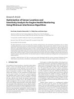
Fig.2.4 illustrates this notation. The coordinate frame {i} is attached to the far (distal)
end of link i. The axis of joint i is aligned with the z-axis. These link and joint parameters
are known as Denavit-Hartenberg parameters and are summarized in Table 2.1.
joint i
Joint i+1
base
link i
zi
Link i-1
yi
xi
{i}
Zi-1
Yi-1
Xi-1
Figure 2.4 The definition of standard Denavit-Hartenberg link parameters [37]
- 11 -
Following this convention; the first joint, joint 1, connects link 0 to link 1. Link 0 is
the base of the robot. Commonly for the first link d1=α1=0 but we could set d1> 0 to
represent the height of the shoulder joint above the base. In a manufacturing system the
base is usually fixed to the environment but it could be mounted on a mobile base such as a
space shuttle, an underwater robot or a truck. The final joint, joint N connects link N−1 to
link N. Link N is the tool of the robot and the parameters dN and aN specify the length of
the tool and its x-axis offset respectively. The tool is generally considered to be pointed
along the z-axis. The transformation from link coordinate frame {i − 1} to frame {i} is
defined in terms of elementary rotations and translations [37].
Table 2.1 Denavit-Hartenberg parameters; their physical meaning, symbol and formal
definition [37]
Joint angle
i
The angle between the xi-1 and xi axes about the zi-1 axis
Link offset
di
The distance from the origin of frame i-1 to the xi axis along
the zi-1 axis
Link length
ai
The distance between the zi-1 and zi axes along the xi axis; for
intersecting axes is parallel to i-1 x i
Link twist
i
The angle from zi-1 axis to the zi axis about the xi axis
The parameters αi and ai are always constant. For a revolute joint θi is the joint
variable and di is constant, while for a prismatic joint di is variable, θi is constant and αi=0.
2.2.1 Rotating coordinate system
The end-effector which suppose as a known coordinate system at the point (x, y, z),
if the z-axis as a rotation then after rotating of the shaft angle coordinates into α (x ', y', z '),
the system architecture is shown in Figure 2.5. The point coordinates are derived as
following [37-38]
- 12 -
z
(x’,y’,z’)
(x ,y ,z)
y
l
α
x
Figure 2.5 The end-effector
Firstly, according to the trigonometric functions can be learned as
l2 = x2 + y2
(2.2)
Coordinate point (x, y, z) in the Z-axis as the rotation axis, after a rotation angle α, the value
of x ', y' calculated as follows
x '= cos (θ + α) = cosθ cosα - sinθ sin
(2.3)
y '= sin (θ + α) = sinθ cosα + cosθ sinα
(2.4)
We know as cosθ = x/l and sinθ = y/l, then Eq.2.5 and Eq.2.6 can be expressed as follows:
x '= xcosα - y sinα
(2.5)
y '= xsinα + y cosα
(2.6)
The Fig.2.5 can be converted by usingEq.2.5 and Eq.2.6 as following:
x ' cos
y ' sin
z ' 0
sin
cos
0
0 x
0 . y
1 z
(2.7)
2.2.2 Homogeneous coordinates
In homogeneous coordinates, the coordinates of the vector which will increase a
length value, expressed as follows:
- 13 -