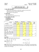
Lecture Strength of Materials I: Chapter 7 - PhD. Tran Minh Tu
Bạn đang xem bản rút gọn của tài liệu. Xem và tải ngay bản đầy đủ của tài liệu tại đây (2.46 MB, 20 trang )
<span class='text_page_counter'>(1)</span><div class='page_container' data-page=1></div>
<span class='text_page_counter'>(2)</span><div class='page_container' data-page=2>
7
CHAPTER
1/10/2013
</div>
<span class='text_page_counter'>(3)</span><div class='page_container' data-page=3>
Contents
7.1. Introduction
7.2. Bending stress
7.3. Shearing stress in bending
7.4. Strength condition
</div>
<span class='text_page_counter'>(4)</span><div class='page_container' data-page=4>
1/10/2013 4
7.1. Introduction
In previous charters, we considered the stresses in the bars caused
by axial loading and torsion. Here we introduce the third fundamental
loading: bending. When deriving the relationship between the bending
moment and the stresses causes, we find it again necessary to make
certain simplifying assumptions.
</div>
<span class='text_page_counter'>(5)</span><div class='page_container' data-page=5>
7.1. Introduction
</div>
<span class='text_page_counter'>(6)</span><div class='page_container' data-page=6>
1/10/2013 6
</div>
<span class='text_page_counter'>(7)</span><div class='page_container' data-page=7>
7.1. Introduction
Segment BC: M<sub>x</sub>≠0, Q<sub>y</sub>=0
=> <b>Pure Bending</b>
</div>
<span class='text_page_counter'>(8)</span><div class='page_container' data-page=8>
1/10/2013 8
7.1. Introduction
</div>
<span class='text_page_counter'>(9)</span><div class='page_container' data-page=9>
7.2. Bending stress
</div>
<span class='text_page_counter'>(10)</span><div class='page_container' data-page=10>
1/10/2013 10
7.2. Bending stress
The positive bending moment causes the
material within the bottom portion of the beam
to <i>stretch</i> and the material within the top portion
to <i>compress</i>. Consequently, between these two
regions there must be a surface, called the
<i>neutral surface</i>, in which longitudinal fibers of
the material will not undergo a change in
length.
</div>
<span class='text_page_counter'>(11)</span><div class='page_container' data-page=11>
7.2. Bending stress
Neutral fiber
c d
a <sub>b</sub>
c <sub>d</sub>
d
dz
1 2
1 2
1 2
1 2
y
y a b
Due to bending moment M<sub>x</sub> caused
by the applied loading, the
cross-section rotate relatively to each other
by the amount of d.
' ' <i>y d</i> <i>d</i>
<i>dz</i> <i>c d</i> <i>cd</i> <i>y</i>
The Normal strain of the longitudinal
fiber <i>cd</i> that lies distance y below the
neutral surface.
<i>z</i>
<i>y</i>
Compatibility
</div>
<span class='text_page_counter'>(12)</span><div class='page_container' data-page=12>
1/10/2013
12
7.2. Bending stress
Equilibrium
<i>z</i>
<i>y</i>
<i>E</i>
Following Hooke’s law, we have.
1
????
y
z
x
dA
x
y
z
K
M<sub>x</sub>
Because of the loads applied in the
plane yOz, thus: N<sub>z</sub>=M<sub>y</sub>=0 and M<sub>x</sub>≠0.
0
<i>z</i> <i>z</i>
<i>A</i> <i>A</i>
<i>E</i>
<i>N</i>
<i>dA</i>
<i>yd A</i>
0
<i>x</i>
<i>A</i>
<i>yd A</i>
<i>S</i>
0
<i>y</i> <i>z</i>
<i>A</i> <i>A</i>
<i>E</i>
<i>M</i>
<i>x</i>
<i>dA</i>
<i>xyd A</i>
0
<i>xy</i>
<i>A</i>
<i>xyd A</i>
<i>I</i>
<i>x</i>
– neutral axis (the neutral axispasses through the centroid C of the
cross-section).
<i>y - axis</i>
– the axis of symmetry of</div>
<span class='text_page_counter'>(13)</span><div class='page_container' data-page=13>
7.2. Bending stress
M<sub>x</sub>>0: stretch top portion
M<sub>x</sub><0: compress top portion
y
z
x
dA
x
y
z
K
M<sub>x</sub>
2
<i>x</i> <i>z</i> <i>x</i>
<i>A</i> <i>A</i>
<i>E</i>
<i>E</i>
<i>M</i>
<i>y</i>
<i>dA</i>
<i>y d A</i>
<i>I</i>
1
<i><sub>x</sub></i><i>x</i>
<i>M</i>
<i>EI</i>
EI<sub>x</sub> – stiffness of beam
M<sub>x</sub> – internal bending moment
– radius of neutral longitudinal fiber
<i>x</i>
<i>z</i>
<i>x</i>
<i>M</i>
<i>y</i>
<i>I</i>
y – coordinate of point
<i>M</i>
Belong to tensile zone</div>
<span class='text_page_counter'>(14)</span><div class='page_container' data-page=14>
7.2. Bending stress
• Stress distribution
- Stresses vary linearly with
the distance y from neutral axis
• Maximum stresses at a cross-section
max max
<i>x</i> <i>t</i>
<i>x</i>
<i>M</i>
<i>y</i>
<i>I</i>
min max
<i>x</i> <i>c</i>
<i>x</i>
<i>M</i>
<i>y</i>
<i>I</i>
yt
max – the distance from N.A to a point farthest away from N.A in the tensile portion
yc
</div>
<span class='text_page_counter'>(15)</span><div class='page_container' data-page=15>
7.2. Bending stress
x
y
<sub>min</sub>
<sub>max</sub>
h/2
h/2
z
M<sub>x</sub>
max
2
<i>x</i> <i>x</i>
<i>x</i> <i>x</i>
<i>M</i>
<i><sub>h</sub></i>
<i>M</i>
<i>I</i>
<i>W</i>
max min
/ 2
<i>x</i>
<i>x</i>
<i>I</i>
<i>W</i>
<i>h</i>
max max
2
<i>t</i> <i>c</i>
<i>h</i>
<i>y</i>
<i>y</i>
min
2
<i>x</i> <i>x</i>
<i>x</i> <i>x</i>
<i>M</i>
<i><sub>h</sub></i>
<i>M</i>
<i>I</i>
<i>W</i>
</div>
<span class='text_page_counter'>(16)</span><div class='page_container' data-page=16>
1/10/2013 16
</div>
<span class='text_page_counter'>(17)</span><div class='page_container' data-page=17>
7.2. Bending stress
</div>
<span class='text_page_counter'>(18)</span><div class='page_container' data-page=18>
1/10/2013 18
</div>
<span class='text_page_counter'>(19)</span><div class='page_container' data-page=19></div>
<span class='text_page_counter'>(20)</span><div class='page_container' data-page=20>
1/10/2013 20
</div>
<!--links-->