- Trang chủ >>
- THPT Quốc Gia >>
- Sinh học
XÂY DỰNG MÔ HÌNH LY HỢP TRÊN CƠ SỞ MÔ HÌNH MA SÁT ĐỘNG LỰC HỌC
Bạn đang xem bản rút gọn của tài liệu. Xem và tải ngay bản đầy đủ của tài liệu tại đây (492.16 KB, 6 trang )
<span class='text_page_counter'>(1)</span><div class='page_container' data-page=1>
<b>MODELLING OF AN AUTOMOTIVE CLUTCH BASED </b>
<b>ON DYNAMIC FRICTION MODEL </b>
<b>Tran Van Nhu* </b>
<i>University of Transport and Communication</i>
ABSTRACT
The clutch dynamic model is important in dynamic research and gearshift control for automated
manual transmission and dual clutch transmission. The dynamic model must describe correctly the
behavior of the clutch in the transitional period for simulation and the controller design ensures
fast and smooth synchronization. This article presents the clutch dynamic model based on the
friction dynamic model. The developed model was simulated using Matlab/Simulink, the
numerical simulation results were compared with the literature models to show the effective of the
developed model.
<i><b>Keywords: Clutch; Clutch dynamic model; Dynamic friction model; Powertrain; Stribeck.</b></i>
INTRODUCTION*
The friction clutch is an element important in
the automotive powertrain, its function is to
transmit torque from the engine to the
transmission system by friction torque. The
friction clutch is present in the various
powertrain such as the Manual Transmission
(MT), the Automated Manual Transmission
(AMT) and the Dual Clutch Transmission
(DCT). The AMTs and the DCTs have more
advantages compared to the manual
transmission and the automatic one. It attracts
many researchers for modeling, simulation
and developing the control law to manage the
clutch/dual clutch during gear shifting and
take-off phase. In the literature, the friction
clutch is usually modeled by the Coulomb
friction model. The Coulomb friction model
does not describe well the Stick-Slip
transition and Stribeck phenomenon. In the
clutch control research to enhance the smooth
driving, the transition phase is very important.
In this paper the author develops a dynamic
model of friction clutch based on the bristle
models.
In the literature, the dynamic friction model is
presented in some works. The Dalh’s model
introduced in [1] was developed for the
simulation of control systems. This model is
*
<i>Tel: 0972 020094, Email: </i>
</div>
<span class='text_page_counter'>(2)</span><div class='page_container' data-page=2>
In [7] the authors introduced a static friction
model Pacejka with the “Magic” formula,
which capture the Stribeck effect and it
applied for modelling the tyre friction. This
model is not continuous and does not capture
the stick-slip transition.
In this paper the author introduces a dynamic
clutch model based on the Bristles model. The
developed model is simulated and compared
with the literature models to show the effectof
the developed model.
CLUTCH MODEL BASED ON THE
STATIC FRICTION MODEL
In the literature, the author majority use
Coulomb friction to model the clutch friction.
This model does not capture the Stribeck
effect. In [8], the author introduced a clutch
model based on the static friction model with
the friction coefficient depending on the
sliding velocity to capture Stribeck effect.
The clutch friction torque in the sliding phase
is determined by equations:
( )sign( )
<i>c</i> <i>c</i> <i>r</i> <i>r</i> <i>n</i>
<i>T</i>
<i>F</i>(1)
where:
<i><sub>c</sub></i> is the clutch geometry constant;<i>n</i>
<i>F</i>
is the normal force;
<i><sub>r</sub></i> is the slidingangular velocity,
(
<i><sub>r</sub></i>)
is the frictioncoefficient depending on the sliding angular
velocity
<i><sub>r</sub></i>:( ) ( ) <i>r</i> <i>s</i> <i>s</i>
<i>r</i> <i>c</i> <i>s</i> <i>c</i> <i>e</i>
<sub></sub>
<sub></sub>
<sub></sub>
(2)
where
<i><sub>c</sub></i> is the Coulomb frictioncoefficient;
<i><sub>s</sub></i> is thestatic friction coefficient;<i>s</i>
is the Stribeck angular velocity;
<i><sub>s</sub></i> is theStribeck exponent.
When the clutch is locked, the torque
transmitting through the clutch is the static
friction torque, which is determined
depending on the state of the system (see
equation (21)).
CLUTCH MODEL BASED ON THE
LUGRE FRICTION MODEL
The clutch dynamics model based on the
Lugre model developed in [5], with the
relative angular velocity
<i><sub>r</sub></i> between theclutch friction disc and the pressure plate. The
LuGre clutch model is described in the
standard form of a first-order nonlinear
differential equation:
- The average deflection of the bristles
<i>z</i>
:| |
( )
<i>r</i>
<i>r</i>
<i>r</i>
<i>dz</i>
<i>z</i>
<i>dt</i> <i>g</i>
(3)
where
<i>g</i>
(
<i><sub>r</sub></i>)
is a function depending on therelative angular velocity
<i><sub>r</sub></i>, which capturesthe Stribeck effect and can be depicted as:
2
0
1
( ) ( ) <i>r</i> <i>s</i>
<i>r</i> <i>c</i> <i>s</i> <i>c</i>
<i>g</i>
<i>e</i>
(4)
with
<sub>0</sub> is the stiffness of the bristles.- The clutch friction torque is determined by
following equation:
0 1 2
<i>c</i> <i>r</i> <i>c</i> <i>n</i>
<i>dz</i>
<i>T</i> <i>z</i> <i>F</i>
<i>dt</i>
<sub></sub> <sub></sub>
(5)
where
<sub>1</sub> is the damping coefficient,
<sub>2</sub> isthe linear viscous friction coefficient,
<i><sub>c</sub></i> isthe clutch geometry constant,
<i>F</i>
<i><sub>n</sub></i> is thenormal force.
THE NEW DYNAMIC MODEL OF THE
FRICTION CLUTCH
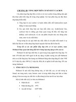
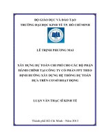
The surfaces of the clutch disc and pressure
plate are very irregular at the microscopic
level. We visualize this contact as two bodies
that make contact through elastic bristles (see
Figure 1) [4]. For simplicity the bristles on
one part are shown as being rigid. When a
torque applies the bristles is deflected which
give rise to the friction torque. If the torque
applied is sufficiently large, the bristles
deflect so much that they will slip.
<i><b>Figure 1. The contact between two surfaces of the </b></i>
</div>
<span class='text_page_counter'>(3)</span><div class='page_container' data-page=3>
The clutch slipping coefficient is defined as
the ratio of internal slipping angular velocity
1 2
and the angular velocity of the inputshaft
<sub>1</sub>1 2
1
(6)
where
<sub>2</sub> is the angular velocity of thebristles head (see Figure 1).
In the sliding phase, the bristles are deflected
maximum, they will slip, therefore
<sub>2</sub>
<sub>2</sub>,where
<sub>2</sub> is the angular velocity of the outputshaft. In this phase, the slipping coefficient
(6) becomes
1 2 1 2
1 1 1
<i>r</i>
(7)
The average deflection of the bristles is
denoted as
<i>z</i>
, the average deflection rate ofthe bristles is given:
2 2
<i>dz</i>
<i>dt</i>
(8)1 2 1 2 1
( ) ( ) <i>r</i>
<i>dz</i>
<i>dt</i>
(9)
The clutch friction torque is a function
depending on the slipping coefficient
andthe normal force
<i>F</i>
<i><sub>n</sub></i>,
,
( )<i>c</i> <i>n</i> <i>c</i> <i>n</i>
<i>T</i> <i>f</i>
<i>F</i>
<i>g</i>
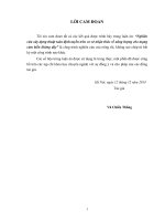
<i>F</i> (10)where
<i>g</i>
( )
is a function capturing theStribeck effect, we use the “Magic” formula [7]
1 1
( ) sin tan tan ( )
<i>g</i>
<i>D</i> <i>C</i> <i>B</i>
<i>E B</i>
<i>B</i>
(11)
where:
<i>c</i>
<i>D</i>
(12)1
2
2 sin <i>c</i>
<i>s</i>
<i>C</i>
<sub></sub> <sub></sub>
(13)
1
tan / (2 )
tan ( )
<i>s</i>
<i>s</i> <i>s</i>
<i>B</i> <i>C</i>
<i>E</i>
<i>B</i> <i>B</i>
(14)
where
<i><sub>s</sub></i> is the Stribeck slippingcoefficient,<i>BCD</i><sub> is the slope of the line </sub>
tangent to the curve
<i>g</i>
( )
at the coordinatesof the origin (
0) (the clutch is locked).In the locked phase, the clutch torque is
independent of the slipping coefficient
(
0), it is a linear function of the bristledeflection,
<i>T</i>
<i><sub>c</sub></i>
<i>z</i>
<sub>0</sub>, where
<sub>0</sub> is thestiffness of the bristles. We have
0
<i>c</i>
<i>dT</i> <i>dz</i>
<i>dt</i>
<i>dt</i> (15)0
1 <i>dT<sub>c</sub></i>
<i>dz</i>
<i>dt</i>
<i>dt</i> (16)
From the equations (9) and (16) we have:
0
1
1 <i><sub>c</sub></i>
<i>r</i>
<i>dT</i>
<i>dt</i>
<i> (17) </i>From the equation (10) we have
( )
( )
( )
( )
<i>c</i> <i>n</i>
<i>c</i> <i>n</i>
<i>n</i>
<i>c</i> <i>n</i>
<i>dT</i> <i>dg</i> <i>dF</i>
<i>F</i> <i>g</i>
<i>dt</i> <i>dt</i> <i>dt</i>
<i>dF</i>
<i>dg</i> <i>d</i>
<i>F</i> <i>g</i>
<i>d</i> <i>dt</i> <i>dt</i>
<sub></sub> <sub></sub>
<sub></sub> <sub></sub>
(18)
From the equations (17) and (18) we have:
0 1
( )
( )
<i>c</i> <i>n</i> <i>r</i>
<i>n</i>
<i>c</i>
<i>dg</i> <i>d</i>
<i>F</i>
<i>d</i> <i>dt</i>
<i>dF</i>
<i>g</i>
<i>dt</i>
(19)
The clutch model is described by the
equations (10), (11) and (19).
SIMULATION RESULTS
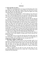
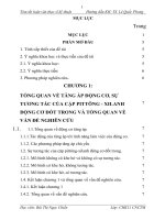
Considering a simplified model of powertrain
as shown in Figure 2. In this figure, <i>T<sub>in</sub></i> is the
engine torque, <i>I</i><sub>1</sub> is the mass moment of
inertia of the engine, flywheel, clutch drum
and pressure plate,
<i>I</i>
<sub>2</sub> is the mass moment ofinertia of the clutch disc, <i>C K</i>, are
respectively the stiffness and damping
coefficient of the clutch disc and the clutch
shaft,
<i>I</i>
<sub>3</sub> is the equivalent mass moment ofthe transmission system and the vehicle mass.
</div>
<span class='text_page_counter'>(4)</span><div class='page_container' data-page=4>
The differential equations of the simplified
powertrain model is given [8]
1
1
2 1 2 1 2
2
3 1 2 1 2
3
1
( )
1
( ) ( )
1
( ) ( )
; 1,..., 3
<i>in</i> <i>c</i>
<i>c</i>
<i>r</i>
<i>i</i> <i>i</i>
<i>T</i> <i>T</i>
<i>I</i>
<i>T</i> <i>C</i> <i>K</i>
<i>I</i>
<i>C</i> <i>K</i> <i>T</i>
<i>I</i>
<i>i</i>
(20)
where
<i><sub>i</sub></i>,
<i><sub>i</sub></i> are respectively the angularvelocities and angular displacements of the
engine, the clutch disc and the vehicle,
<i>T</i>
<i><sub>r</sub></i> is theload torque,
<i>T</i>
<i><sub>c</sub></i> is the clutch friction torque,which is modelled in the above sections.
For the clutch model based on the static
friction model, it is necessary to determine the
clutch torque in the locked state. In the locked
state, we have
<sub>1</sub>
<sub>2</sub>. From the first andsecond sub-equation of the equation (20)we
can find the clutch torque as following
equation:
1 2 1 2
12
*
1 2
( ) ( )
<i>in</i>
<i>c</i>
<i>T I</i>
<i>T</i>
<i>I</i> <i>I</i>
<i>C</i>
<i>K</i>
<i>I</i>
(21)
Applying simulation with the parameters of the
simplified powertrain model as following [8]:
1 2.7
<i>I</i> kgm2;
<i>I</i>
<sub>2</sub>
0.1
kgm2;<i>I</i>
<sub>2</sub>
2.65
kgm2;16300
<i>C</i> Nm/rad; <i>K</i> 60Nm.s/rad. The
parameters of clutch models are [8]:
<i><sub>s</sub></i>
0.8
;0.6
<i>c</i>
;
<i><sub>s</sub></i>
2
;
<i><sub>s</sub></i>
10
rad/s;
<i><sub>c</sub></i> 0.28m;4
0 5.10
Nm;
<sub>1</sub>
3
Nm;
<sub>2</sub>
0
Nm.s/rad;3
10
<i>s</i>
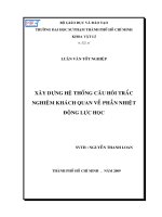
<sub></sub> ; <i>B</i>100. The function
<i>g</i>
( )
isshown in Figure 3.
<i><b>Figure 3. Function</b></i>
<i>g</i>
( )
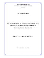
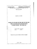
The first simulation is implemented by the
time-varying normal force
<i>F</i>
<i><sub>n</sub></i> as shown inFigure 4. The engine torque <i>T<sub>in</sub></i> and the load
torque
<i>T</i>
<i><sub>r</sub></i> are constants, the initial slippingangular velocity is
<i><sub>r</sub></i>(0) 100 rad/s. Thesimulation results with three clutch models
are shown in Figures 4 and Figure 5. At the
first stage, the clutch is synchronized (from 0s
to 2s), the normal force
<i>F</i>
<i><sub>n</sub></i> increases. In thiscase, the behaviors of the clutch modeled by
the three methods are similar. Then, at the
second stage (from 2s to 3s), the normal force
decreases. Naturally, the clutch switches from
the locked state to the slipping state. The state
switching of the clutch modelled by the static
friction model and the developed model
occurs almost at the same time when the
normal force decreases to 50daN (at 2.75s,
see Figure 4). While that of the clutch
modeled by the LuGre model occurs when the
normal force is zero (about 3s), which does
not capture the reality behavior of the clutch.
Figure 5 showed that, at the state switching
moment (about 2.75s), the clutch torque based
on the static friction model oscillates with a
large amplitude. The developed model
oscillates less and captures the behavior of
stick-slip moment.
<i><b>Figure 4. First test - time-varying normal force: </b></i>
<i>angular velocities </i>
</div>
<span class='text_page_counter'>(5)</span><div class='page_container' data-page=5>
developed model are similar, that of Lugre
clutch modelis slightly different from the
other two.
<i><b>Figure 5. First test - time-varying normal force: </b></i>
<i>clutch torque </i>
According the function of the clutch, the
normal force is variable to synchronize and
disengage the clutch disc. In this case, the
developed clutch model captures well the
clutch behavior in the process of
synchronization and disengagement.
<i><b>Figure 6. Second test - time-varying engine </b></i>
<i>torque: angular velocities </i>
CONCLUSION
In the literature, the clutch model is modelled
based on the static friction model. This model
does not capture the stick-slip transition. The
clutch model based on the Lugre friction
model capture well the behavior of clutch in
the synchronization process. However, in the
disengagement process, this model does not
capture the behavior of the clutch by the
non-drift property.
The developed model in this paperhas
eliminated the disadvantages of the two
models above. It captures well the Stribeck
effect, the stick-slip transition. However, this
model is not affine in the control input
<i>F</i>
<i><sub>n</sub></i>.REFERENCES
1. P. Dahl (1968), “A solid friction model”, The
Aerospace Corporation, El Segundo, CA,
Technical Report TOR-0158H3107–18I-1.
2. H. Olsson, K. J. Åström, C. C. de Wit, M.
Gäfvert, P. Lischinsky (1998), “Friction Models
<i>and Friction Compensation”, Eur. J. Control, vol </i>
4, No.3, pp. 176–195.
3. D. A. Haessig, B. Friedland (1991), “On the
<i>modelling and simulation of friction”, J. Dyn. </i>
<i>Syst. Meas. Control, vol 133(1), pp. 354–362. </i>
4. C. Canudas de Wit, H.Olsson, K.J.Astrom,
P.Lischinsky (1995), “A new model for control of
<i>systems with friction”, IEEE Trans. Autom. </i>
<i>Control, vol 40, pp. 419–424. </i>
5. M. Aberger, M. Otter (2002), “Modelling
Friction in Modelica with the LuGre Friction
<i>model”, trong International Modelica Conference, </i>
<i>Proceedings, Oberpfaffenhofen. </i>
6. R. Nouailletas (2009), “Modélisation hybride,
identification, commande et estimation d’états de
système soumis à des frottements secs -
Application à un embrayage robotisé.”, Grenoble
INP, Grenoble.
7. <i>H. B. Pacejka (2006), Tyre and Vehicle </i>
<i>Dynamics. Butterworth-Heinemann. </i>
</div>
<span class='text_page_counter'>(6)</span><div class='page_container' data-page=6>
TĨM TẮT
<b>XÂY DỰNG MƠ HÌNH LY HỢP TRÊN CƠ SỞ MƠ HÌNH MA SÁT </b>
<b>ĐỘNG LỰC HỌC </b>
<b>Trần Văn Như*</b>
<i>Trường Đại học Giao thông Vận tải </i>
<b> </b>
Mơ hình động lực học ly hợp quan trọng trong nghiên cứu động lực học và điều khiển quá trình
chuyển số trên hệ thống truyền lực tự động hóa AMT và DCT. Mơ hình động lực học cần mô tả
được hành vi của ly hợp trong giai đoạn q độ để mơ phỏng chính xác và thiết kế bộ điều khiển
đảm bảo đóng mở ly hợp nhanh và êm dịu. Bài báo này tác giả trình bày mơ hình động lực học ly
hợp xây dựng trên cơ sở mơ hình ma sát động lực học. Mơ hình được mơ phỏng bằng phần mềm
Matlab/Simulink, kết quả mơ phỏng được so sánh với các mơ hình trước đây cho thấy sự đáp ứng
hành vi của mơ hình.
<i><b>Từ khóa: Ly hợp; Mơ hình động lực học ly hợp; Mơ hình ma sát động lực học; Hệ thống truyền </b></i>
<i>lực; Stribeck.</i>
<i><b>Ngày nhận bài: 01/8/2017; Ngày phản biện: 14/8/2017; Ngày duyệt đăng: 30/8/2017 </b></i>
*
</div>
<!--links-->