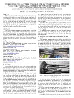
Phân tích ứng xử cơ học của phân đoạn dầm hộp bê tông cốt thép trong cầu dây văng một mặt phẳng dây tt tiếng anh
Bạn đang xem bản rút gọn của tài liệu. Xem và tải ngay bản đầy đủ của tài liệu tại đây (1.11 MB, 26 trang )
MINISTRY OF EDUCATION AND TRAINNING
THE UNIVERSITY OF TRANSPORT AND COMMUNICATIONS
BUI NGOC TINH
ANALYSIS OF MECHANICAL BEHAVIOR OF
REINFORCED CONCRETE BOX GIRDER IN
ONE-PLANE CABLE STAYED BRIDGE
Domain:
Transport Construction Engineering
Code:
9580205
SUMMARY OF DOCTORAL THESIS
Hanoi - 2020
INTRODUCTION
1. The necessity of the thesis
Cable stayed bridge was firstly built in Vietnam since 1998 (My
Thuan bridge). Sofar, a number of cable stayed bridges were designed
and constructed. Many of them using two planes of cables as well as the
I and Π type cross section with incline webs to ensure the aerodynamic
stability, enhance the lateral rigidity and therefore is able to pass over
long span.
In comparison to two-plane cable stayed bridge, the one-plane
cable stayed bridge help to separate two traffic flows on the bridge by
location the plane of cable in the middle of the cross-section; open the
better view for transportation and also brings better aesthetic feeling.
However, since the cable is vertically located in the middle of the cross
–section; they subject to only the vertical bending of the girder and do
not contribute to the torsional strength of the cross-section. That is the
reason why the box-type of cross-section (which has high torsional
rigidity and aerodynamic stability) is normally used for one-plane cable
stayed bridge. In Vietnam, there are two one-plane cable stayed bridges,
they are Bai Chay bridge and Nga ba Hue bridge. In which, Bai Chay
bridge ranked the first among the list of longest span one-plane cable
stayed bridge in the world at the time of construction (2006).
In the design of one plane cable stayed bridge, the cables are
located in the middle of the top slab of the cross section; therefore the
top slab has to subjected to rather large pull-out loading in out-of-plane
direction. This type of loading result in the compression in the slab (due
to the incline of cable), the bending effect in the girder and also the local
pull-out loading on the slab; the combination of these effects lead to a
complicated stress-strain condition in the slab. Because of this reason,
othotropic steel decks or composite deck solution is used in many oneplane cable stayed bridges, such as the Rama VIII bridge pass over Chao
Phraya river in Bangkor.
1
Reinforced concrete box girder can avoid the fatigue, vibration
and large deformation problem as can be happened in steel box girder.
However, there is no guidelines for calculation of reinforced concrete
slab subjected to the local pull-out loading combine with overall
compression and bending as explained above.
In order to avoid the local damage on the slab, the design solution
in Bai Chay bridge is using the tension pipe connecting the top slab to
two bottom edge of the cross-section in order to transfer the pull-out
loading in the top slab to the bottom of webs.
This is an acceptable solution in term of loading capacity, but
leading to many difficulties in construction; and the effect of the
solution will be limited at the position where the incline angle of the
cable is small and nearly perpendicular to the vertical pipe.
Therefore, we decided to carry out the doctoral thesis namely
“Analysis of mechanical behavior of reinforced concrete box girder
in one-plane cable stayed bridge” in order to propose the theoretical
analysis model, validated by experimental study, to analyse the
mechanical behavior of reinforced concrete girder in one-plane cable
stayed bridge. Also, base on the proposed model, analyse the
effectiveness of the strengthening method using vertical pipe as used in
Bai Chay bridge.
The Aims, Objectives and Scope of research as summarized as
follows:
2. Aims
- Analyse and select the appropriate calculation model for
analysing the local behavior of reinforced concrete slab subjected
to out-of-plane loading;
- Perform experiments to validate the proposed theoretical model;
-Using the proposed model in analysing, evaluating the
mechanical behavior of reinforced concrete box girder in oneplane cable stayed bridge.
- Compare and conclude on the effective solution for
2
strengthening the concrete box girder subjected to cable force in
term of loading capacity.
3. Objectives and the Scope of study
Structure: Reinforced concrete box girder subjected to pull out
loading in the middle of the top slab;
Material: Reinforced concrete box girder, taking into account the
non-linear behavior of steel and concrete.
Loading: limited to static loadings.
4. Methodology
- Literature review, determine the problem to be studied.
- Experimental study;
- Numerical modeling.
5. Novel contributions of the study
- Scientific contributions: Non-linear material model is employed for
numerical modeling the behavior of concrete box girder of one-plane
cable stayed bridge. Number of experimental experiments were tested to
validate the numerical result.
- Application contribution: the thesis results can be applied in
modeling the practical concrete box girder one-plane cable stayed
bridge; contributes in design and evaluation of cable stayed bridge.
- Main contributions:
Propose the “total strain crack” model in analyse the local
behavior of concrete box girder in one-plane cabale stayed bridge.
Propose the experimental speciments and tests to validate the
theoretical model in this type of structure.
Numerical analysis of the mechanical behavior of reinforced
concrete box girder bridge of one-plane cable stayed bridge subjected to
local pull-out loading of cable forces, which will help to evaluate the
effectiveness of the strengthening methods.
6. Structure of thesis
3
The thesis consists of the Introduction, four main chapters and the
Conclusion and Perpectives.
Introduction
Chapter 1: Problem statement;
Chapter 2: Study on the mathematical model for analyse the
stress-strain condition of reinforced concrete box type girder of oneplane cable stayed bridge;
Chapter 3: Experimental study for validating the “total strain
crack” model for reinforced concrete slab subjected to out-of-plane
inclined loading
and the Publication list of the Author.
CHAPTER 1. PROBLEM STATEMENT
Cable stayed bridge was introduced in the 16th century and was
widely applied from 19th century. Some initial cable stayed bridges were
the combinations of cable stayed bridge and suspension bridge
(Brooklyn bridge, for example). In the development of cable stayed
bridge, people used the two-plane, three-plane and also four-plane of
cables. The two-plane cable type were mostly used, however the
inconvenience of this type of bridge was the aesthetics and the difficulty
in lanes arrangement. One-plane cable type is more beautiful and helps
to reduce the dimension of the substructure. However, the most
unfavourable problem for one-plane cable stayed bridge is that the cable
system can not support the main girder to againts twisting, aerodynamic
unstability and vibration. In order to enhance the twisting capability and
aerodynamic stability, box-type girder was normally employed.
For steel box girder, the weight of girder, the thickness of slab is
relative small sothat for long span bridge, the girder is usually vibrate
with high frequency and leading to the damage on the Asphalt cover
layer (happened in Rama VII bridge with the span length equals to
450m). For concrete box girder bridge, one-plane cable leads to a
4
reinforced concrete slab subjected to out-of-plane pull out loading. This
problem will be the central question to be solved in this thesis.
At the moment (2020), there are two one-plane cable stayed
bridges have been built in Vietnam. They are Bai Chay and Tran Thi Ly
bridge. In this type of bridge, a clear design of load transfer path from
cable to the girder is necessary. At the moment, there is not many
researches or studies in this issue, especially the local behavior of the
slab on the anchorage zone. The literature review showed that it is
necessary to continue the research on the connection between cable and
the slab of reinforced concrete box girder.
The bridge design specifications of Vietnam has not directly
mentioned on the analysis of reinforced concrete slab subjected to local
pull-out loading. The stress-strain condition in the local anchorage zone
of the cable is not similar with the local anchorage zone of tendons in
prestress concrete; since it is the combination the overall bending, the
overall compression of the slab and the local pull-out at the anchorage
region.
In this thesis, the author focus on both theoretical aspect and
experimental aspect of this problem.
CHAPTER 2. THEORETICAL MODEL OF REINFORCED
CONCRETE BOX GIRDER SUBJECTED TO CABLE FORCE IN
ONE-PLANE CABLE STAYED BRIDGE
2.1. The current status of the problem
Cable stayed bridge is designed due to the national design
specications and standard. In Vietnam, bridge design specifications
TCVN 11823:2017 is not enough to design the cable stayed bridge,
sothat people needs to refer to other specifications/standards which take
into account the aerodynamics stability of bridge under wind load. The
problem of reinforced concrete slab subjected to the tensile force of
cable, is the combination of three loading condition: reinforced concrete
5
slab subjected to compression, to bending and the local pull-out loading.
Vietnameses design specifications and standards have not mentioned on
this combination of loadings
2.2. Propose the “total strain crack” model for analysing the
behavior of reinforced concrete slab subjected to cable force in
one-plane cable stayed bridge
Reinforced concrete slab subjected to incline out-of-plane loading
is a common type of structure widely used in bridge and other
construction. For bridges, this type of structure is applied in the slab of
one-plane cable stayed bridge or in the hollow tower with the anchorage
located inside. This type of structure subjects to overall bending, inplane compresion, local out-of-plane loading and was studied in both
modeling and experimental aspects.
In numerical modeling aspect, the “multi-layer method” was
introduced, in which the slab is divided into many layer, each layer is
assumed to have uniforme tension or compression stress perpendicular
to the layer. In this type of approach, the reinforcement and concrete is
modeled as a “layer”, and can help to estimate the stress-strain condition
in the slab direction. However, this method can not take into acount the
effect of the stress perpendicular to the slab direction, for example the
shear stress. Also, this type of method cannot take into account the
contribution of local reinforcement, which normally located
perpendicular to the loading direction. In order to solve this problem,
Hrynuk and Vecchio proposed the “multi-layer method” but taking into
acount the shear effect. The method of Hrynuk and Vecchio helps to
solve the reinforced concrete slab subjected to vertical loading.
However, can not modeling the effect of incline loading and cannot
estimate the forming and the development of local cracks.
In order to modeling the happen and development of cracks in
reinforced concrete structure; there are two approaches. They are the
“discrete” model and the “smeared crack” model. In “discrete” model,
the discontinuity in the displacement field is used to model the crack.
6
Extended finite element method (X-FEM, ED-FEM) is employed for
numerical modeling and the “discontinuity” in displacement is taken
into account by an additional shape function for the displacement (see
Ibrahimbegovic, Armero,..). It is difficult to apply this type of approach
for three-dimensional reinforced concrete structure; since it is needed to
have the contact relation equation between concrete, reinforcement and
bonding in all three dimensions, and will require a huge computational
work.
The second approach is so-called the smeared crack model. In
which, the displacement field is still assumed to be continuous field after
crack. In term of finite element method, the crack is modeled as a
displacement inside the finite element, but not in the nodes. The
“smeared crack” model was studied by many authors, but initialy
proposed by Vecchio and then developed by Selby for threedimensional element, namely “total strain crack” model. The “total
strain crack” model theoretically can model the forming and
development of crack in three-dimensional refion, therefore can be
applied in such type of structure like deep beam, or the anchorage zone
of prestressed concrete construction. The application of “total strain
crack” model in modeling the reinforced concrete slab subjected to
perperdicular compression was performed by Ngekpe and Barisua and
give reasonable results. However, this model have not been applied in
modeling the reinforced concrete slab subjected to out-of-plane incline
compression or tension. In the experimental aspect, there is only few
reports on the reinforced concrete subjected to vertical loading, but not
many research on the reinforced concrete slab subjected to incline
loading. In this thesis, the author will also carry out experimental
research on this issue.
In the “total strain crack” model, the direction of principal stress
is assumed to be same with the direction of principal strain.
7
Figure 1. Stress-strain condition
Since this model apply for reinforced concrete material then the
technical properties of concrete and reinforcement is necessary,
including: young modulus, Poission ratio, tensile strength, compressive
strength and the fracture energy. For fracture energy (Gf), one can refers
to the value from CEB-FIP 1990 as shown in equation 1 and table 1.
G
f
G
fo
f cm
f cm o
0 .7
(1)
In which, fcm is the average compressive strength of concrete, f cm0
is the reference compressive strength, equals to 10 MPa. The value of
reference fracture energy (Gf0) is selected due to the maximum
aggregation dimension (Dmax) as shown in Table 1:
Table 1. Reference fracture energy Gfo vs Dmax
Dmax (mm)
8
16
32
Gf0 (J/m2)
25
30
58
The stress-strain relation of concrete under compression and
tension of reinforced concrete in principal direction is shown in figure 2.
8
Figure 2. Relation between stress-strain of reinforced concrete
in principal direction in compression and tension
There are a number of mathematical models were proposed for
the stress-strain relation of concrete under compression and tension.
Equation 2 introduces the equation of Thorenfeldt for compression and
Equation 3 introdues the equation of Vecchio and Collins for tension.
Theorenfeldt equation:
i
f fp
p
n 1
In which:
n 0 .8 0
n
i
p
nk
(2)
nÕu 0 p
1
, k
fcc
17
nÕu
p
0 .6 7
62
fcc
Vecchio and Collins equation for compression:
f c1
E c 1
'
ft
1 200 1
0 1 cr
(3)
1 cr
The shear stress – shear strain behavior of concrete is assumed to
be linear, with a reduction factor β
G
cr
G
(4)
9
In which β is the reduction factor of shear modulus G due to
cracks. β equals to from 0 to 1.
For reinforcement, the elasto-plastic model can be employed:
E s si
f si
f
y
0 si
si
y
(5)
y
The stress-strain relation of concrete and reinforcement is the
basic to develop the stress-strain relation for reinforced concrete
material in principal direction. This is the main continuous equation for
“total strain crack” model.
CHAPTER 3. EXPERIMENTAL STUDY ON REINFORCED
CONCRETE SLAB SUBJECTED TO INCLINE LOADING
In ordre to prove the capability of “total strain crack” model in
modeling the behavior of reinforced concrete slab subjected to incline
loading, experiments were carried out and the results are compared to
the numerical analysis.
3.1. Experimental model
Reinforced concrete slabs with three incline angles of loading (α)
(25, 45 and 70°) are considered.
Figure 3. Experimental samples
In each incline angle, three experimental samples are made. The
reinforced concrete slab is 10cm in depth, 500cm in width and 600cm in
length. The compressive strength of concrete is 40MPa, the maximum
aggregate dimension of concrete is 20mm. Two layers of reinforcement
are arranged, with the spacing is 15×15cm. A steel plate is put under the
compression force, on the top face of the slab and welded into
10
reinforcement layer of the slab. An incline compression (P) was put on
the middle-top of the slab. The compression P increases with time until
the slab is failure; strain in concrete and reinforcement, deflection in the
slab are measured during compression.
3.2. Modeling results
The experimental slabs are numerical modeled using “total strain
crack” model; the input parameter of material are showed in the table 2.
Table 2. Material parameters
No.
1
2
3
4
5
Parameter
Symbol
Reinforcement CB400V
Yield strength
fy
Young modulus
Es
Concrete C40
Compressive strength
f'c
Young modulus
Ec
Poisson ratio
v
Value
Unit
400
20000
MPa
MPa
40
31975
0.2
MPa
MPa
From the above parameters, the stress-strain relation curve of
reinforced concrete is made. The reinforced concrete slab is modeled by
finite element method (3d brick element for concrete, 1d element for
steel bar) (see figure 4)
Figure 4. Reinforced concrete slab model
The compression force P increases in 11 levels (with Pu is the
ultimate load of compression), which the specific value in the Table 3.
11
Table 3. Values of compression force (P)
Level of
compression
Level 1
Level 2
Level 3
Level 4
Level 5
Level 6
Level 7
Level 8
Level 9
Level 10
Level 11
Pi/Pu
=25°
12
24
36
48
60
72
84
96
108
120
132
0,1Pu
0,2 Pu
0,3 Pu
0,4 Pu
0,5 Pu
0,6 Pu
0,7 Pu
0,8 Pu
0,9 Pu
Pu
1.1 Pu
Value kN)
=45°
8
16
24
32
40
48
56
64
72
80
88
=70°
6.5
13
19.5
26
32.5
39
45.5
52
58.5
65
71.5
The calculated deflection of the slab, stress in the reinforcement
of the slab with different incline angle is shown in the Table 4 and
Figure 5. In the figure 5, the dashed lines show the result at 20cm from
the central point of the slab while the normal lines show the result at the
central point of the slab.
Table 4. Calculation results
Deflection (mm)
Stress in steel bar (MPa)
Loading
level
α=25
1
0.17
0.17
0.19
2
0.32
0.35
3
0.56
4
°
α =45°
α =70°
0.5
3.4
7.1
0.41
8.1
7.8
15.9
0.58
0.8
15.8
18.1
45.8
0.91
1.13
1.44
46.1
59.6
97.5
5
1.42
1.86
2.13
91.9
111.3
133
6
2.03
2.58
2.93
142.8
172.5
183.8
7
2.7
3.31
3.75
198.7
221
236.6
8
3.39
4.16
5.7
257.3
273.9
297.9
α =45
°
α =70
12
°
α=25°
9
5.58
5.09
7.17
326.4
332.7
343.6
10
7.61
6.17
9.18
400
400
400
11
10.81
9.24
12.16
400
400
400
Figure 5. Relation between compression loading and deflection, stress
in the reinforcement of three incline slabs due to calculation results
Figure 6 shows the overall deformation of the slab and the
distribution of stress in concrete at the ultimate loading P u (level 10) for
different incline slabs.
13
α = 70°
P=65 kN
α = 45°
P=80kN
α=25°
P = 120 kN
Figure 6. Deformation and stress in reinforcement at ultimate loading
level (level 10)
Table 4 and figure 6 shows the tensile stress in reinforcement
reaches the yield strength (400 MPa) at level 10, so-called the ultimate
level of loading. The ultimate loading for 25°, 45° and 70° reinforced
concrete slab is 120kN, 80kN and 65kN, respectively.
3.3. Comparison between the calculation results and the
experimental results.
Due to experiment, the deflection and loading at the ultimate
level for each incline slab is shown in Table 5.
Table 5. Defection of slab and the ultimate loading due to
experimentals results
Experimental results
No of
Specimens
Specimens 1
Specimens 2
Distance
to the
central
point of
the slab
(cm)
R=0
R=20
R=0
Specimens 250
Deflection
(mm)
7.22
6.27
7.04
Specimens 450
Ultimate
load
(kN)
142
141.1
14
Deflection
(mm)
9.94
7.20
9.08
Ultimate
load
(kN)
100.2
92.8
Specimens 700
Deflection
(mm)
12.72
8.48
12.20
Ultimate
load
(kN)
79.6
79.85
Specimens 3
R=20
R=0
R=20
6.02
7.32
6.25
6.68
9.28
7.25
140
97.32
8.39
12.01
9.08
80.39
The experimental results showed that the ultimate loading for
25°, 45° and 70° is 141kN, 96kN and 80kN, about 15% to 20% higher
than the calculated ultimated values (120kN, 80kN and 60kN). The
differences come from the higher compressive of concrete (normally
higher than the design value = 40Mpa) and the contribution of bonding
between steel bar and concrete.
Figure 7. Comparison between calculation and experimental results
15
The crack patterns from the modeling result is similar to the
visible cracks in the specimens (figure 8). Those cracks include the
cracks due to overall bending and due to local failure at anchorage zone.
Figure 8. Failure in specimens and due to modeling
Figure 8 clearly shows that the crack patterns due to modeling
and due to experiment is similar.
2.3. Conclusion of Chapter 3
Experimental results show that the “total strain” crack model
capable of modeling the behavior of reinforced concrete slab subjected
to incline loading, both in term of deformation, deflection, ultimate
loading as well as the failure type, with resonable accuracy for practical
design.
CHAPTER 4. APPLICATION OF THE „TOTAL STRAIN
CRACK“ MODEL FOR ANALYSING OF A REINFORCED
CONCRETE BOX GIRDER IN ONE-PLANE CALBE
STAYED BRIDGE
4.1. Selection of the calculation structure
In order to prove the capability of the total strain crack model,
one need to apply this model into a specific problem of one-plane cable
stayed bridge. For that reason, the typical cross-section of Bai Chay
bridge was selected. In this calculation, stress-strain condition of
reinforced concrete slab is modeled for different incline of cables, and
with the cable force ranging from 0.2fpy to 0.7fpy). Two type of crosssections, with and without steel pipi enhencement, are considered.
16
Calculation result also help to evaluate the effectiveness of using steel
pipe in strenthening the one-plane cable stayed bridge box-girder slab.
The calculation is limited for the serviceability state.
4.2. Analysis results
In order to simplify the model, a segment of girder was taken into
account, separated from other part of the girder at the middle point
between two adjacent cable.
Figure 9. The finite element model for a segment of box girder
Table 6. Dimension of the box girder
No
Dimensions
Value
Unit
1
Depth of the girder
3,70
m
2
Width of the top slab
25,00
m
3
Width of the bottom slab
8,00
m
4
Thickness of the top slab
0,25
m
5
Thickness of the bottom slab
0,20
m
6
Thickness of the web
0,35
m
Material parameters
Compressive strength of concrete f’c
17
=
45
MPa
Density of concrete
kg/m3
yc
=
2400
Tesile limitation
[σk]
=
3,354 MPa
Compressive limitation
[σn]
=
27
MPa
Yield limite
fy
=
390
MPa
Young modulus
Es
=
205000
Lateral reinforcement
d1
=
22
mm
Longitudinal reinforcement
d2
=
16
mm
Stress limitation for concrete
Reinforcement
MPa
In reality, the cross-section between two adjacent boundary is
considered to be fix boundary.
Figure 10. Boundary condition
The loading acting on the bridge include: selfweight of the main
girder, deadload of the superimposed structures, live-load and other
special loadings such as wind load or earth-quake. These load are
normally transfer to the cable force, then from the cable to the tower.
Theredore, we can only concentrate on analysis the box-girder subjected
to cable forces.
18
Figure 11. Detail of anchorage zone from cable to box girder
The cable consists of 61 tendons, diameter of each tendon is
15,2mm. The cable force transfer to the concrete box girder at the slab
as show in the figure. Due to the detail of anchorage reinforcement, the
cable force can be assumed to be uniformly distributed on the anchorage
plate. The incline angle of cable ranges from 25° to 70° and results in
different stress-strain condition in the top slab of the girder. Due to the
design of the cable, the stress in the cable is normally between 0.3fpy
and 0.6fpy. When the girder subjected to wind load, the stress in the
cable can increase a little bit to 0,65fpy. Therefore, in this thesis, we
calculate the box girder subjected to cable force ranging from 0.5fpy to
0.7fpy.
Figure 12 to Figure 16 shows the stress-strain condition for
reinforced concrete box girder subjected to 50o incline loading equals to
0.5fpy.
19
Figure 12. Displacement in z direction
Figure 13. Displacement in X direction
20
Figure 14. Displacement in Y direction
21
Figure 15. Stress in reinforcement and in pipe
Figure 16. Crack region
Table 7. Stress-strain and deformation condition of box-girder when
using and not using the pipe enhancement.
0.5fpy
Loading
Withou
t pipe
0.6fpy
With
pipe
22
Withou
t pipe
With
pipe
0.7fpy
Withou
t pipe
With
pipe
Vertical
displacement (mm)
tensi
X
on
Maxi dire
mum ctio com
pres
stress
n
sion
in
conc
tensi
Y
rte
on
dire
(MP
com
ctio
a)
pres
n
sion
tensi
on
Stress in
reinforcedm com
ent (MPa)
pres
sion
Crack width (mm)
1.898
1.693
2.479
2.161
3.098
2.666
3.35
3.35
3.35
3.35
3.35
3.35
-16.90
-19.44
-20.88
-23.77
-24.972
-28.249
3.35
3.35
3.35
3.35
3.35
3.35
-21.22
-20.72
-25.76
-25.17
-30.198
-29.61
138.31
119.99
194.16
158.34
246.72
197.73
-122.6
-141.0
-156.3
-179.9
-192.72
-221.77
0.203
0.173
0.297
0.237
0.385
0.300
In Table 7, when stress exceeds the tensile limitation, we write
the tensile value.
4.3. Conclusion of chapter 4
In the chapter 4, the author applied the “total strain crack”
model which has been proposed in chapter 2 and validated in chapter 3,
to analyse the mechanical behavior of a typical reinforced concrete box
girder for one-plane cable stayed bridge.
The calculation result clearly showed the stress-strain condition
at reinforced concrete box slab, stress in reinforcement, and especially,
indicated the local crack zone around the anchorage zone as well as the
maximum crack width. Theses results are important, especially to the
bridge located in the corrosion environment (eg. near by the sea) such as
Bai Chay bridge.
The calculation result for different incline angle of cable, and
different cable force also clearly explain the effectiveness of using steel
pipe enhancement system for reinforced concrete box girder (like in Bai
Chay bridge). The calculation result shows that the pipe enhacement
system is reasonable, especially to the big angle cable, but not really
useful for small angle cable.
23
CONCLUSION AND PERPECTIVES
In this thesis, the author has studied on the theoretical aspect,
experimental aspect of reinforced concrete box girder in one-plane cable
stayed bridge.
The literature review carried out in Chapter 1 showed that the
remaining problem to be considered in mechanical behavior of
reinforced concrete box girder in one-place cable stayed bridge is to
propose a suitable mathematical analysis model, which allows to
calculate, evaluate the local stress-strain condition in the reinforced
concrete slab of the girder, at the position near by the anchorage zone.
The position where the slab has to subjected to the local pull-out
loading, overall bending, overall compression simultaneously.
Based on the literature review in chapter 1, in chapter 2, the
author has studied on different models of reinforced concrete and
propose to use the “total strain crack” model to modeling the behavior of
reinforced concrete box girder in one-plane cable stayed bridge. The
proposed “total strain crack” model is then validated in chapter 3 and
applied to modeling a practical reinforced concrete box girder and
clearly indicate the capability of this model for such type of problem.
This is also be the main and new scientic results of the thesis.
In chapter 4, the author applied the total strain crack model in
modeling the stress-strain condition in a typical cross-section of
reinforced concrete box girder subjected to incline cable force. The
calculation results show the effectiveness of the design enhancement
solution.
The propose model in this thesis can be developed for analyzing
the cable force which taking into account the impact loading (due to
vibration of cable or break down of cable), fatigue analysis of reinforced
concrete at anchorage zone of cable. The propose model can also be
applied to pre-calculate the effectiveness of enhancement solution at
local anchorage zone of box girder, which are:
- Directly anchorage to bottom face of top slab,
- Using diagram;
- Using pipe system;
in order to choose the appropriate solution for each section,
each girder.
This is also the direction for the next research of the author
24