Shop manual máy đào HuynDai R170W-9 (Phần 5) - P5.13
Bạn đang xem bản rút gọn của tài liệu. Xem và tải ngay bản đầy đủ của tài liệu tại đây (448.67 KB, 5 trang )
5-28
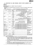
GROUP 13 EPPR VALVEGROUP 13 EPPR VALVE
COMPOSITIONCOMPOSITION
EPPR (Electro Proportional Pressure Reducing) valve consists of electro magnet and spool valve
installed at main pump.
Electro magnet valveElectro magnet valve
Receive electric current from MCU and move the spool proportionally according to the specific
amount of electric current value.
Spool valveSpool valve
Is the two way direction control valve for pilot pressure to reduce main pump flow.
When the electro magnet valve is activated, pilot pressure enters into flow regulator of main pump.
Pressure and electric current value for each modePressure and electric current value for each mode
1)1)
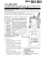
HOW TO SWITCH THE STAGE (1.0 HOW TO SWITCH THE STAGE (1.0 ↔ 2.0) ON THE CLUSTER 2.0) ON THE CLUSTER
You can switch the EPPR valve pressure set by selecting the stage (
1.0 ↔ 2.0
).
Management
·
Service menu
-
Power shift (standard/option) : Power shift pressure can be set by option menu.
·
21093CD67M
21093CD67N 21093CD67P
21093CD67ZZ
Enter the password
(1)(1)
(2)(2)
(3)(3)
2)2)
1. 1. PUMP EPPR VALVEPUMP EPPR VALVE
Mode
Pressure
Electric current
(
mA
)
Engine rpm
(at accel dial 10)
kgf/cm
2
psi
Standard
(Stage : 1.0)
P 10 142 340
±
30 2000
±
50
S
15
±
3 213
±
40 405
±
30 1900
±
50
E
20
±
3
284
±
40 470
±
30 1750
±
50
Option
(Stage : 2.0)
P 0 0 215
±
30 2000
±
50
S 5
±
3 71
±
40 280
±
30 1900
±
50
E 10
±
3 142
±
40 340
±
30 1750
±
50
5-29
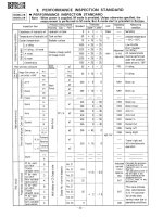
OPERATING PRINCIPLEOPERATING PRINCIPLE (pump EPPR valve)
StructureStructure
3)3)
P Pilot oil supply line (pilot pressure)
T Return to tank
A Secondary pressure to flow regulator at main pump
Neutraleutral
Pressure line is blocked and A oil returns
to tank.
Operatingperating
Secondary pressure enters into A.
P
T
A
P
T
A
P
T
A
2
34 5
6
7
1
1 Sleeve
2 Spring
3 Spool
4 O-ring
5 O-ring
6 Solenoid valve
7 Connector
PT
A
PT
A
5-22(1)
5-22(2)
(1)(1)
(2)(2)
(3)(3)
5-30
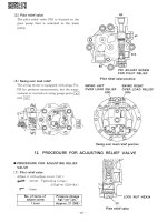
EPPR VALVE CHECK PROCEDUREEPPR VALVE CHECK PROCEDURE
Check electric current value at EPPR valveCheck electric current value at EPPR valve
Disconnect connector CN-75 from
EPPR valve.
Insert the adapter to CN-75 and install
multimeter as figure.
Start engine.
Set S-mode and cancel auto decel
mode.
Position the accel dial at 10.
If rpm display show approx 1900
±
50
rpm
check electric current at bucket
circuit relief position.
Check pressure at EPPR valveCheck pressure at EPPR valve
Remove plug and connect pressure
gauge as figure.
·
Gauge capacity : 0 to 50
kgf/cm
2
(0 to 725
psi
)
Start engine.
Set S-mode and cancel auto decel
mode.
Position the accel dial at 10.
If rpm display show approx 1900
±
50
rpm
check pressure at relief position of
bucket circuit by operating bucket control
lever.
If pressure is not correct, adjust it.
After adjust, test the machine.
Multimeter
CN-75
EPPR valve
Main pump
Adapter(P/no.:21Q6-50410)
Valve casing
Main pump
Pressure adjusting
screw locknut
Valve casing
CN-75
EPPR valve
Pilot pressure
supply line
①
②
③
④
⑤
⑥
Spec : 100~700
mA
Spec : 2~25
kgf/cm
2
(30~350
psi
)
14W95MS21
14W95MS22
4)4)
(1)(1)
①
②
③
④
⑤
⑥
⑦
(2)(2)
5-31
2. 2. BOOM PRIORITY EPPR VALVEBOOM PRIORITY EPPR VALVE
COMPOSITIONCOMPOSITION
The boom priority EPPR valve is built in a manifold and mainly consisting of valve body and coil.
This EPPR valve installed under the solenoid valve.
CONTROLCONTROL
The boom priority EPPR valve has to be controlled by a specific electronic amplifier card, which is
supplying the coil with a current 580 mA at 30
Ω
and 24 V.
1)1)
2)2)
21095MS14
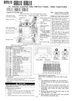
OPERATING PRINCIPLEOPERATING PRINCIPLE
StructureStructure
3)3)
(1)(1)
1 5
2
4 6
P
A
T
3Control spool
1 O-ring
2 Support ring
3 Valve body
4 Coil
5 Connector
6 Cover cap
OperationOperation
In de-energized mode the inlet port (P) is closed and the outlet port (A) is connected to tank port
(T).
In energized mode the solenoid armature presses onto the control spool with a force
corresponding to the amount of current. This will set a reduced pressure at port A. The setting is
proportional to the amount of current applied.
Maximum pressure reliefMaximum pressure relief
If a pressure from outside is applied on port A the valve may directly switch to tank port (T) and
protect the system before overload.
(2)(2)
(3)(3)
P
T
A
P : Pilot supply line
T : Return to tank
A : Secondary pressure to flow MCV
5-32
EPPR VALVE CHECK PROCEDUREEPPR VALVE CHECK PROCEDURE
Check electric current value at EPPR Check electric current value at EPPR
valvevalve
Disconnect connector CN-133 from
EPPR valve.
Insert the adapter to CN-133 and install
multimeter as figure.
Start engine.
If rpm display approx 1900
±
50
rpm
check electric current in case of
combined boom up and swing operation.
Check pressure at EPPR valveCheck pressure at EPPR valve
Remove hose from A5 port and connect
pressure gauge as figure.
·
Gauge capacity : 0 to 50
kgf/cm
2
(0 to 725
psi
)
Start engine.
If rpm display approx 1900
±
50
rpm
check pressure at relief position of
bucket circuit by operating bucket control
lever.
If pressure is not correct, adjust it.
After adjust, test the machine.
Boom priority
EPPR valve
Solenoid valve
CN-133
Multimeter
Adapter
(P/no.:21Q6-50410)
Boom priority
EPPR valve
Solenoid valve
A5
Pressure
gauge
Spec : 400~600
mA
(combined boom up and swing operation)
Spec : 12~37
kgf/cm
2
(170~530
psi
)
(bucket relief operation)
21095MS15
21095MS16
①
②
③
④
2)2)
(1)(1)
①
②
③
④
⑤
(2)(2)